Programming modern microcontrollers: lecture 1
Summary of the first lecture on the programming of modern microcontrollers on the example of STM32 and the operating system RIOT. Lectures are given at the Institute of Information Technologies MIREA on Saturdays, from 12:50 in the auditorium on the 4th floor of Building D. The classes are given 1.5 hours for the lecture itself and 3 hours for practical classes in the IoT laboratory of the Samsung Academy on the lecture topic.
Hi, Giktayms! As we promised, we begin the publication of lecture notes, which are now being read at the IT Institute of MIREA. According to the results of the first introductory lecture, we decided to slightly change the structure of the course - instead of the planned two streams of 5 classes there will be one stream of 7 classes. This will allow for a quieter pace to sort out a number of auxiliary questions, as well as articles with a summary will appear on the GT every week throughout March and April, and not a week later, as was planned earlier.
Nevertheless, it is impossible to completely cover such an extensive topic in seven lectures, therefore in some places the presentation will be abstract - although to compensate for this, we will try to indicate in which direction to look to those who want to sort out this or that issue on their own.
The course is designed for second and third year students familiar with the C language and basic concepts of electronics and electrical engineering. Prior acquaintance with microcontrollers is not required.
The goal of the course is the development of skills that allow working freely with microcontrollers on the ARM Cortex-M core at the modern level and, if so desired, move in the direction of further deepening their knowledge.
Today’s lecture is the first, so the general concepts will be discussed: what is a microcontroller in general and why is it needed, what is firmware and how does it work out, why do we need an operating system, and finally how to work with git. The result of the practical lesson is your own GitHub repository with OS source codes, as well as a successfully configured build environment on the local computer.
In short, the microcontroller is a classic example of a “system on a chip”, which includes both the processor core and a set of auxiliary and peripheral devices, which allow the microcontroller to be completely self-sufficient in many cases.
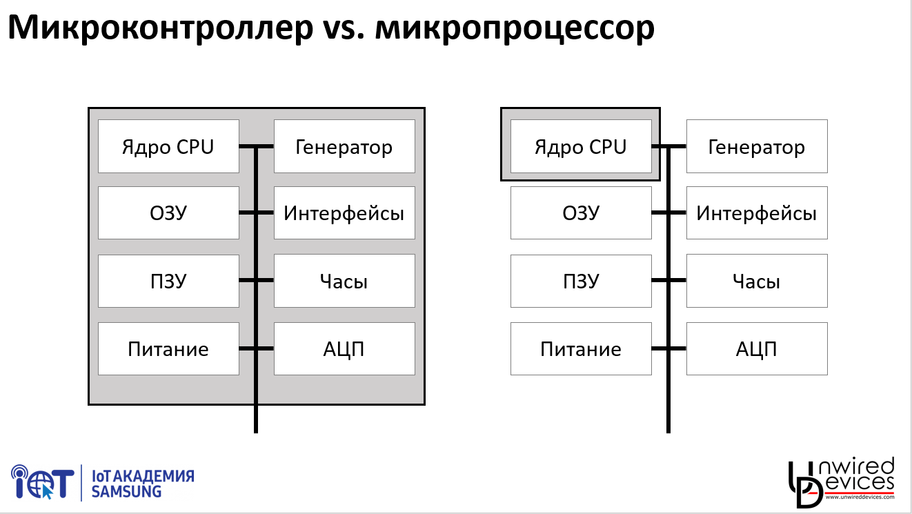
In a typical microprocessor, similar to what is in any PC or smartphone, almost all modules that can be attributed to auxiliary (power, clocking, even basic peripheral devices) are brought out of the chip itself, despite the fact that working without them is a microprocessor can not.
In the microcontroller, on the contrary, not only the subsystems necessary for its operation, but also the mass of peripheral devices, which may be required in various practical tasks, are implemented on the same chip as the core. Moreover, many manufacturers of microcontrollers compete with each other not in terms of core performance or memory, but in abundance and functions of peripheral devices.
Microcontrollers have been developing for a long time in parallel with microprocessors - the Intel 8051 architecture, which is still found in industrial products, was developed in 1980. At some point, their development lines begin to intersect with microprocessors - for example, older microcontroller models have interfaces for external RAM, and microprocessor manufacturers integrate more and more peripherals onto the chip (just remember that at the dawn of the "personal computer" even the cache memory was accumulated by external microcircuits) - but in any case they remain two essentially different branches of development.
Actually, the purpose of creating microcontrollers was the possibility of reducing the cost and miniaturization of various devices that require some small computing power: using a single chip, for which it’s quite simple to apply power, makes it much easier to design and manufacture a PCB compared to a set of 4-5 separate chips .
Of course, the microcontroller has its limitations - it is technically impossible to pack in one crystal that in a large PC takes up half the rather big board.
As part of the course, we will work with STM32L151CC microcontrollers with 32 KB of RAM, 256 KB of ROM and a maximum operating frequency of 32 MHz (on the Nucleo-L152RE boards there are slightly more serious chips - 80 KB of RAM and 512 KB of ROM).
In general, there can be four types of memory inside a microcontroller:
You can look at the organization of the memory of a particular controller in its datasheet. For example, here is the datasheet on the STM32L151CC , on page 51 of which a memory card of this family is presented.
It is not difficult to notice that all four types of memory about which we spoke occupy a very small piece of the card - and in most of the picture there is a list of all peripheral devices available in the controller.
The fact is that everything - in general everything - communication with all peripheral devices of the microcontroller and all its settings is carried out using only two operations:
Everything inside the microcontroller is necessarily mapped to some address. These addresses are called registers (do not confuse with registers of the processor - there are data in registers of processors on which the processor performs operations; in the registers we are talking about there are some special data that are displayed in a specific way on the state of various hardware units of the microcontroller).
So, for example, if we want the third leg of port A of the microcontroller (PA2, numbering to go from scratch) to appear “1”, we need to write “1” to the third bit of the register located at 0x4002014. And if this leg is configured as an input and we, on the contrary, want to know what value is on it, we need to read the third bit of the register at 0x40020010.
Yes, in order to indicate to the controller, this foot is the input or output - write the corresponding values to the corresponding bits at 0x40020000.
This is an important point in understanding the work of the microcontroller: absolutely everything that is not computational operations, for which the processor core itself is responsible, is done by writing or reading one or another register. Whatever libraries are in the top of your program - in the end, it all comes down to registers.
Of course, working with numeric addresses is rather inconvenient, so for each Cortex-M core microcontroller there is a CMSIS (Cortex Microcontroller Software Interface Standard) library, the most important component of which for us is the header file that describes the relatively readable registers in the particular controller the names.
With CMSIS, the PA leg described above will look like this:
All names of registers and field values in them are described in the document that can be considered the Bible of the microcontroller programmer Reference Manual (it is, of course, its own for each family of controllers, reference is given to RM0038, corresponding to the STM32L1 family). I note that more than 900 pages RM0038 is not a very large amount of information, you can easily find controllers with manuals of 1500-2000 pages. There is hardly anyone who remembers at least a third of such a manual by heart, but the ability to quickly navigate in it is an indispensable quality for a good programmer.
Of course, this code is only conditionally human-readable. Using alphabetic names instead of addresses drastically reduces the percentage of errors in the code and increases its readability, but still very far from what most people would call "normal" code.
Understanding this, manufacturers of controllers began to issue auxiliary libraries that collect sets of register accesses as functions — for example, if you work with registers directly to turn on any such generator, you need to do two things (put in 1 bit, including the generator, and wait until the flag appears in 1 indicating that the generator has entered the mode), then they will be merged as a function of switching on the generator in such a library.
In the case of the STM32, the main library is called the Standard Peripherals Library, also known as the StdPeriphLib, or SPL. In addition to it, there is ST library LL, and a number of third-party libraries - for example, LibOpenCM3 . Third-party libraries often support controllers from other manufacturers, but due to the prevalence of STM32, they are usually in the first place.
So, when using SPL, the references to the registers that we made to light the LED turn into appeals to the functions GPIO_Init and GPIO_Write.
However, it is impossible not to notice that among professional developers the attitude towards SPL is ambivalent.
On the one hand, SPL allows you to sketch the project’s skeleton much faster, especially when using graphic controller configuration tools, such as the STM32 CubeMX . At the same time, the code will be quite good (as far as their set of peripheral devices and capabilities you use) matches between different controllers of the STM32 family.
On the other hand, as practice shows, in a complex project there is no question “what to do if something will work wrong” - there is a question “what to do when everything is going wrong”. In SPL, as in any library, there may be errors, besides, the logic of the SPL developers may not coincide with your idea of what should happen to the controller during certain actions - as a result, if you get into such a situation, you still have to open source SPL and see exactly what happens there at the register level. In practice, this can sometimes take no less than writing the functionality you need from scratch.
In addition, the libraries released by a specific chip manufacturer, although they allow to migrate between the chips of this manufacturer to some extent, but you will not be able to jump, for example, from STM32L1 to ATSAMD21 with code written for SPL.
SPL and code readability does not always help - in programs written with its use, it is often possible to see half-page sheets consisting of SPL calls alone.
Finally, SPL solves only one problem - abstraction from hardware and work with registers. However, as the project progresses, you will encounter several more, for example:
All these tasks — and many more along the way — are solved by the operating system.
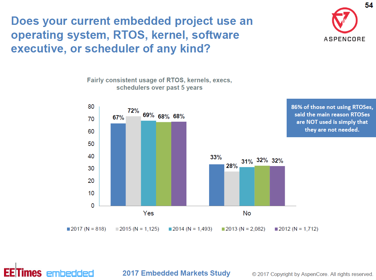
Despite the fact that the OS requires for its existence scarce controller resources (usually 5-20 KB of permanent memory and as much operational), the advantages of using the OS are so great that at the moment about 70% of projects use professional software for embedded systems or another OS.
Strictly speaking, at the lower level, the OS can use vendor libraries like SPL. However, as part of our course, we will work with RIOT OS , whose lower-level code for the STM32 family is written in registers — we will not touch upon working with SPL at all.
The reason for this is simple: although in general we will study the work of the OS and the controller at the top level, but in cases where we want to go into the details of their operation, we still have to go down to the level of registers, and the layer in the form of SPL would be pretty strong interfered with. Having mastered the general principles of working with controllers, if you wish, you can understand the functioning of the SPL yourself, especially since the vast majority of STM32 textbooks available online are based on it.
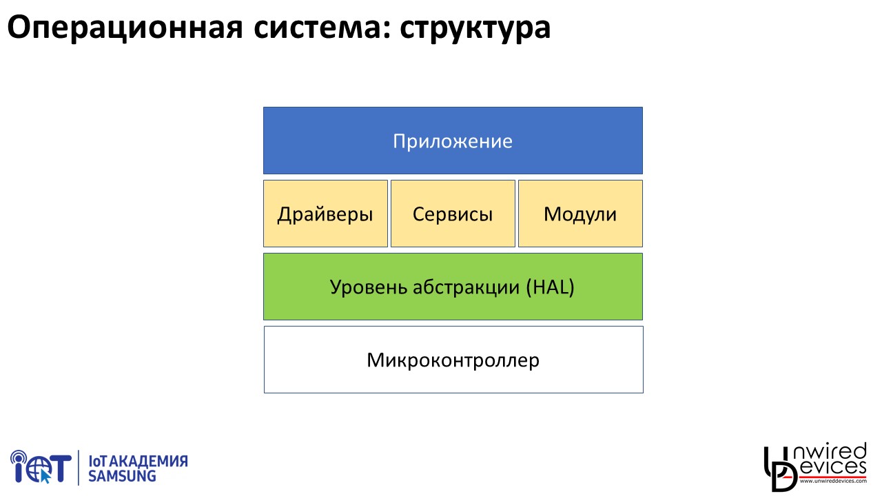
In the form of a maximally simplified OS scheme, you can think of it as a set of components aligned into a specific hierarchy:
One of the reasons why we will work with RIOT OS and without using any development tools (IDE) is in the recently received magical thinking, according to which many functions are implemented by pressing the corresponding buttons in the IDE, and without these buttons impossible (so, I met the statement that the dignity of the Arduino IDE is the ability to assemble the same code for different hardware platforms by selecting the desired platform in the menu; according to the narrator, other systems did not have this functionality, since whether the corresponding menu).
More precisely, if we recall Arthur Clarke’s phrase about technologies that are indistinguishable from magic, then this thinking can rather be called pseudomagical, reformulating the aphorism as “any technology well enough hidden from the user, becomes indistinguishable from magic.”
In fact, of course, there is no special menu function in the Arduino IDE, as in any other IDE, it is just a graphical shell for accessing some completely standard functions and features of modern software systems.
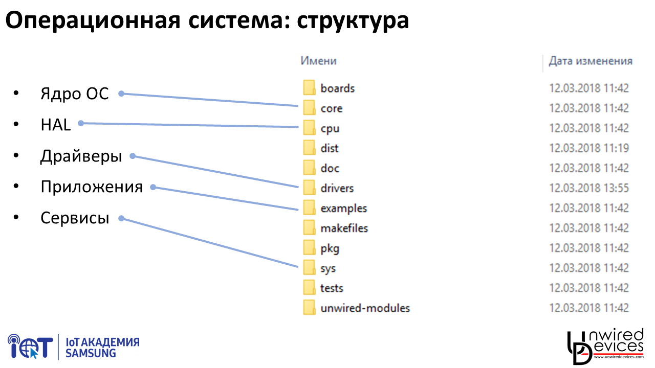
If we look at how RIOT OS looks like a set of files on a disk, we can easily recognize the components of the system decomposed into folders: the HAL is in the cpu folder (and if we open it, we will see descriptions for dozens of different microcontrollers, from AVR to PIC32), descriptions built on these controllers of boards - boards, external device drivers - drivers, OS kernel - core, system and auxiliary OS services - sys, user applications - examples.
One of the important points that distinguishes microcontrollers from large systems is that almost always (and in our case always) user applications do not exist as separate files loaded independently of the OS, but compiled with the OS, the entire set of drivers and modules in single file loaded into the memory of the microcontroller. There are several reasons for this - starting with the absence of the need for a separate download of applications, which makes it possible to simplify the entire system, and ending with the need to assemble the OS and a set of drivers and modules for a specific device in order to save it by no means infinite memory.
We will work with source codes in the version https://github.com/unwireddevices/RIOT/tree/mirea - this is a branch from the main development of RIOT OS, in which, by Unwired Devices, support for STM32L1 microcontrollers has been improved, as well as some useful services, for example , timers based on a real-time clock, including a millisecond timer.
Source codes can be downloaded from Github by selecting the “Clone / Download” and “Download ZIP” buttons, but creating your own repository is a better option. To do this, register on GitHub, then return to the above repository and click the "Fork" button - the source codes will be copied to your account, from where you can work with them without any problems.
I will not describe here the details of working with GitHub and Git - there are a lot of excellent step-by-step tutorials on the Internet that don't make sense to repeat.
Due to the fact that the OS takes over all the interaction with the microcontroller, the simplest possible application in general is no more difficult than the traditional “Hello world” on a large PC:
In the structure of our OS, this application is located in the example / hello-world folder in the main.c file (it is already there).
However, obviously, to compile it, you must first configure the build environment. This is done differently in different OS.
1. Windows 8 and older. Unfortunately, you have to use MinGW, slow and uncomfortable. The procedure for installing the necessary components is described in sufficient detail here . I note that to work with Git / GitHub, you will also have to install Git for Windows separately , which will drag your trimmed version of MinGW. If desired, all this can be reduced to one MinGW terminal, but it will not solve the problems with a very low MinGW speed and its overall inconvenience.
In general, Windows 7 and Windows 8, as you can see, are not the best choice for development.
2. Windows 10. Open the Microsoft Store, find Ubuntu in it and install. If, when you first start Ubuntu, you swear to the Windows component that is turned off, open the “Turn Windows features on or off” system application, find “Windows Support for Linux” there and turn it on.
All further work takes place in the Ubuntu environment, much more comfortable and fast than MinGW.
Download the compiler and its accompanying utilities from here (note: you need a 64-bit version for Linux!), Open Ubuntu, unpack the archive and point the system to the path to it:
The last two commands will prescribe the installation paths to the compiler and utilities in the .bashrc file, so you don’t have to manually install them each time you start Ubuntu. Pay attention to the back fraction before $ and the double arrow >> at the end - without the first the path will be written incorrectly, without the second (with a single arrow) you will erase all previous contents of .bashrc.
After this, the console command arm-none-eabi-gcc --version should report that there is such a compiler, and its version is 7.2.1 (for the time being).
To work with Git, you need to generate a pair of private and public keys with the ssh-keygen command, then copy the public key (in Ubuntu under Windows, this can be done with the command cat ~ / .ssh / id_rsa.pub, then select the output with the mouse and press Enter - it will be copied to the clipboard) and add it to your GitHub account. After that, you can work with GitHub from the command line using the git command.
Nb:If you have not previously worked on the Linux command line, then pay attention to two useful points: the up and down arrow keys scroll through the history of the commands entered, and the Tab key completes the path you have typed to the end of the file or folder (i.e., cd / opt / gcc - turns into the string cd / opt / gcc-arm-none-eabi-7-2017-q4-major). The latter also serves as a good test of whether you are typing the right way - if it’s wrong, it will not be supplemented for obvious reasons. If there are several possible additions, then double-clicking Tab will display them all.
Nb:in Windows, it will be more convenient for you to work if the OS source codes themselves are located in a folder directly accessible from Windows, for example, Documents / git / RIOT. From under MinGW it will be available along the path / c / Users / vasya / Documents / git / RIOT, from under Ubuntu - / mnt / c / Users / vasya / Documents / git / RIOT. In this case, you can freely use to work with the code, for example, text editors written for Windows, such as Notepad ++.
3. Linux. Installing the build environment is no different from the instructions for Windows 10, except that you do not need Microsoft Store. Also, do not look for gcc-arm-none-eabi in the repository of your distribution - download the most recent version from its official website.
After installing the build environment, open the console, go to the folder with RIOT and to the subfolder examples / hello-world, then run the command make .
Most likely, it will quickly be interrupted by an error and a message that you do not have enough unzip (under Windows 10, it is not installed by default), make or other utilities. In Windows 10, they can be installed with the command (the list of missing is given in a simple list with a space):
After installation, try running make again - or rather, the best option is to call the command “ make clean && make ”: the first one cleans up the garbage left over from the previous attempt. Without it, the compiler may mistakenly decide that some of the already assembled modules have not changed, and not recompile it - as a result you will receive the firmware assembled from pieces of old and new code.
NB: in the original RIOT, the hello-world application is built for the native architecture, that is, in our case, a laptop or desktop, x86. However, in our code, the unwd-range-l1-r3 board using the stm32 controller is already specified in the project build parameters, so you should see the line at the beginning of the procedure
If you succeed behind it, you will see a dozen or two lines starting with the make command — this is building the individual components of the operating system. All will end with a message about the successful creation of the firmware file mirea.elf, indicating the size of various types of data (the amount of used flash memory and RAM).
Something like this:

So, we figured out a bit how the microcontroller looks like, downloaded the source codes of our OS, set up the build environment and made sure that it works.
In the next lesson, we will take a closer look at the microcontroller’s device, starting with the GPIO ports, and load the first application into it - according to the old tradition, the LED will blink - and then we will return to the operating system and take a closer look at what components it consists of and how it is configured assembly.
PS And as a supplement - a lively 360-degree lecture record (the recording of seminars was not held for an understandable reason: “there is little talk at the blackboard”, much of the work is already being done with individual students who are doing something or not):

Hi, Giktayms! As we promised, we begin the publication of lecture notes, which are now being read at the IT Institute of MIREA. According to the results of the first introductory lecture, we decided to slightly change the structure of the course - instead of the planned two streams of 5 classes there will be one stream of 7 classes. This will allow for a quieter pace to sort out a number of auxiliary questions, as well as articles with a summary will appear on the GT every week throughout March and April, and not a week later, as was planned earlier.
Nevertheless, it is impossible to completely cover such an extensive topic in seven lectures, therefore in some places the presentation will be abstract - although to compensate for this, we will try to indicate in which direction to look to those who want to sort out this or that issue on their own.
The course is designed for second and third year students familiar with the C language and basic concepts of electronics and electrical engineering. Prior acquaintance with microcontrollers is not required.
The goal of the course is the development of skills that allow working freely with microcontrollers on the ARM Cortex-M core at the modern level and, if so desired, move in the direction of further deepening their knowledge.
Today’s lecture is the first, so the general concepts will be discussed: what is a microcontroller in general and why is it needed, what is firmware and how does it work out, why do we need an operating system, and finally how to work with git. The result of the practical lesson is your own GitHub repository with OS source codes, as well as a successfully configured build environment on the local computer.
Microcontroller
In short, the microcontroller is a classic example of a “system on a chip”, which includes both the processor core and a set of auxiliary and peripheral devices, which allow the microcontroller to be completely self-sufficient in many cases.
In a typical microprocessor, similar to what is in any PC or smartphone, almost all modules that can be attributed to auxiliary (power, clocking, even basic peripheral devices) are brought out of the chip itself, despite the fact that working without them is a microprocessor can not.
In the microcontroller, on the contrary, not only the subsystems necessary for its operation, but also the mass of peripheral devices, which may be required in various practical tasks, are implemented on the same chip as the core. Moreover, many manufacturers of microcontrollers compete with each other not in terms of core performance or memory, but in abundance and functions of peripheral devices.
Microcontrollers have been developing for a long time in parallel with microprocessors - the Intel 8051 architecture, which is still found in industrial products, was developed in 1980. At some point, their development lines begin to intersect with microprocessors - for example, older microcontroller models have interfaces for external RAM, and microprocessor manufacturers integrate more and more peripherals onto the chip (just remember that at the dawn of the "personal computer" even the cache memory was accumulated by external microcircuits) - but in any case they remain two essentially different branches of development.
Actually, the purpose of creating microcontrollers was the possibility of reducing the cost and miniaturization of various devices that require some small computing power: using a single chip, for which it’s quite simple to apply power, makes it much easier to design and manufacture a PCB compared to a set of 4-5 separate chips .
Of course, the microcontroller has its limitations - it is technically impossible to pack in one crystal that in a large PC takes up half the rather big board.
- Operating frequencies rarely exceed 200 MHz, and more often are in the region of tens of megahertz.
- The amount of RAM is within a megabyte, and more often around tens of kilobytes.
- The amount of memory programs - within a megabyte, and more often - in the region of tens to hundreds of kilobytes.
As part of the course, we will work with STM32L151CC microcontrollers with 32 KB of RAM, 256 KB of ROM and a maximum operating frequency of 32 MHz (on the Nucleo-L152RE boards there are slightly more serious chips - 80 KB of RAM and 512 KB of ROM).
Memory
In general, there can be four types of memory inside a microcontroller:
- Permanent memory (flash memory) is used to store user programs and, sometimes, some of the settings of the microcontroller itself. If, when referring to the characteristics of the microcontroller, the amount of memory is written, without specifying which one - as a rule, this is about flash. The contents of the flash is not reset when power is lost, the information storage period in it under normal conditions is usually not less than 10 years.
- RAM is used to execute user programs and to store “momentary” data. RAM is always reset when you restart or turn off the power, and may also not be saved when entering certain sleep modes. Microcontrollers often do not have a clear separation between program memory and data memory — as a result, the term “run from RAM” can be found, meaning that not only the data but also the program itself are in RAM; however, these are quite exotic cases.
- Eeprom. Also applies to permanent memory, but differs significantly from flash memory with its characteristics. Flash has two big drawbacks that make it very inconvenient for saving some current data from the program - first, the flash has a limited number of overwrites of the same cell, and second, the flash can often work with whole pages that hundreds of bytes in size, even if you only need to overwrite one byte. EEPROM of these shortcomings is deprived - its service life is usually ten times longer (from 100 thousand to 1 million overwrites), and it is possible to work in it with each byte separately. For this reason, EEPROM is used for permanent storage of data generated by the program itself (measurement archives, program settings, etc.), its typical size is in units of kilobytes, but it is not in all controllers.
- The system memory . Areas of permanent memory, inaccessible to the user for writing, and recorded in the production of the microcontroller. Usually they contain the executable loader code (described below), but some calibration constants, serial numbers or even auxiliary libraries for working with peripheral devices can also be stored.
You can look at the organization of the memory of a particular controller in its datasheet. For example, here is the datasheet on the STM32L151CC , on page 51 of which a memory card of this family is presented.
It is not difficult to notice that all four types of memory about which we spoke occupy a very small piece of the card - and in most of the picture there is a list of all peripheral devices available in the controller.
Registers
The fact is that everything - in general everything - communication with all peripheral devices of the microcontroller and all its settings is carried out using only two operations:
- read the value at the given address
- write the value to the specified address
Everything inside the microcontroller is necessarily mapped to some address. These addresses are called registers (do not confuse with registers of the processor - there are data in registers of processors on which the processor performs operations; in the registers we are talking about there are some special data that are displayed in a specific way on the state of various hardware units of the microcontroller).
So, for example, if we want the third leg of port A of the microcontroller (PA2, numbering to go from scratch) to appear “1”, we need to write “1” to the third bit of the register located at 0x4002014. And if this leg is configured as an input and we, on the contrary, want to know what value is on it, we need to read the third bit of the register at 0x40020010.
Yes, in order to indicate to the controller, this foot is the input or output - write the corresponding values to the corresponding bits at 0x40020000.
This is an important point in understanding the work of the microcontroller: absolutely everything that is not computational operations, for which the processor core itself is responsible, is done by writing or reading one or another register. Whatever libraries are in the top of your program - in the end, it all comes down to registers.
Of course, working with numeric addresses is rather inconvenient, so for each Cortex-M core microcontroller there is a CMSIS (Cortex Microcontroller Software Interface Standard) library, the most important component of which for us is the header file that describes the relatively readable registers in the particular controller the names.
With CMSIS, the PA leg described above will look like this:
int pin_num = 2; /* PA2*/
GPIOA->MODER &= ~(0b11 << (pin_num*2)); /* сбросили биты настройки ножки PA2 на всякий случай */
GPIOA->MODER |= 0b01 << (pin_num*2); /* установили биты настройки ножки PA2 в 01 — выход */
GPIOA->ODR |= 1 << pin_num; /* установили ножку PA2 в 1 */
GPIOA->MODER &= ~(0b11 << (pin_num*2)); /* сбросили биты настройки ножки PA2, теперь это вход */
uint32_t pa2_value = GPIOA->IDR & (1 << pin_num); /* прочитали состояние ножки PA2 */
All names of registers and field values in them are described in the document that can be considered the Bible of the microcontroller programmer Reference Manual (it is, of course, its own for each family of controllers, reference is given to RM0038, corresponding to the STM32L1 family). I note that more than 900 pages RM0038 is not a very large amount of information, you can easily find controllers with manuals of 1500-2000 pages. There is hardly anyone who remembers at least a third of such a manual by heart, but the ability to quickly navigate in it is an indispensable quality for a good programmer.
Of course, this code is only conditionally human-readable. Using alphabetic names instead of addresses drastically reduces the percentage of errors in the code and increases its readability, but still very far from what most people would call "normal" code.
Understanding this, manufacturers of controllers began to issue auxiliary libraries that collect sets of register accesses as functions — for example, if you work with registers directly to turn on any such generator, you need to do two things (put in 1 bit, including the generator, and wait until the flag appears in 1 indicating that the generator has entered the mode), then they will be merged as a function of switching on the generator in such a library.
In the case of the STM32, the main library is called the Standard Peripherals Library, also known as the StdPeriphLib, or SPL. In addition to it, there is ST library LL, and a number of third-party libraries - for example, LibOpenCM3 . Third-party libraries often support controllers from other manufacturers, but due to the prevalence of STM32, they are usually in the first place.
So, when using SPL, the references to the registers that we made to light the LED turn into appeals to the functions GPIO_Init and GPIO_Write.
However, it is impossible not to notice that among professional developers the attitude towards SPL is ambivalent.
On the one hand, SPL allows you to sketch the project’s skeleton much faster, especially when using graphic controller configuration tools, such as the STM32 CubeMX . At the same time, the code will be quite good (as far as their set of peripheral devices and capabilities you use) matches between different controllers of the STM32 family.
On the other hand, as practice shows, in a complex project there is no question “what to do if something will work wrong” - there is a question “what to do when everything is going wrong”. In SPL, as in any library, there may be errors, besides, the logic of the SPL developers may not coincide with your idea of what should happen to the controller during certain actions - as a result, if you get into such a situation, you still have to open source SPL and see exactly what happens there at the register level. In practice, this can sometimes take no less than writing the functionality you need from scratch.
In addition, the libraries released by a specific chip manufacturer, although they allow to migrate between the chips of this manufacturer to some extent, but you will not be able to jump, for example, from STM32L1 to ATSAMD21 with code written for SPL.
SPL and code readability does not always help - in programs written with its use, it is often possible to see half-page sheets consisting of SPL calls alone.
Finally, SPL solves only one problem - abstraction from hardware and work with registers. However, as the project progresses, you will encounter several more, for example:
- Peripheral virtualization . For example, your controller has only one real-time clock (RTC) timer, on which you can set two independent events - and at the same time, a serious program can easily have five or six functions that the timer uses regularly (for periodic tasks) or one-time (for example, for timing the delay), and other timers are not suitable for them. In this situation, you will need a function manager, which will organize the simultaneous operation of all these procedures with the only available timer.
- Multitasking . Any rather complex system quickly acquires a large number of various procedures that need to be triggered at different intervals or for various events. The loop (), familiar to many in Arduino, already at half a dozen of mixed procedures that have been rammed into it, begins to look like an ugly monster, and an attempt to organize within its framework also the prioritization of tasks strikes terror into the hearts of people. At this point, you will want to bring all the tasks from loop () into independent functions, leaving only the scheduler in the loop, which will access the specified tasks. This will be the first rudiments of multitasking (we will talk about its full implementation, types of planners and communication between different tasks in the next lecture).
- Division of labor. As soon as the development of the system reaches the level at which several people lead it, you will face the task of segregation of duties - in addition to optimizing the development, which also has a purely practical meaning: there are quite a few universal programmers in the world who can debug work with equal efficiency. processor, and network stack, and user interface. With much greater probability, each of your team members will be better able to understand one area - so you will quickly want to separate these areas at the code level, so that, for example, the user interface specialist is not forced to deal with the controller registers via a line , and vice versa. This will break up your code into separate modules that communicate with each other through standardized APIs.
All these tasks — and many more along the way — are solved by the operating system.
Despite the fact that the OS requires for its existence scarce controller resources (usually 5-20 KB of permanent memory and as much operational), the advantages of using the OS are so great that at the moment about 70% of projects use professional software for embedded systems or another OS.
Strictly speaking, at the lower level, the OS can use vendor libraries like SPL. However, as part of our course, we will work with RIOT OS , whose lower-level code for the STM32 family is written in registers — we will not touch upon working with SPL at all.
The reason for this is simple: although in general we will study the work of the OS and the controller at the top level, but in cases where we want to go into the details of their operation, we still have to go down to the level of registers, and the layer in the form of SPL would be pretty strong interfered with. Having mastered the general principles of working with controllers, if you wish, you can understand the functioning of the SPL yourself, especially since the vast majority of STM32 textbooks available online are based on it.
operating system
In the form of a maximally simplified OS scheme, you can think of it as a set of components aligned into a specific hierarchy:
- bottom level - the code directly working with the microcontroller;
- medium level - components included in the OS itself, but not dependent on a specific controller: drivers for various external devices, task scheduler, various auxiliary services;
- the top level is the user application itself.
One of the reasons why we will work with RIOT OS and without using any development tools (IDE) is in the recently received magical thinking, according to which many functions are implemented by pressing the corresponding buttons in the IDE, and without these buttons impossible (so, I met the statement that the dignity of the Arduino IDE is the ability to assemble the same code for different hardware platforms by selecting the desired platform in the menu; according to the narrator, other systems did not have this functionality, since whether the corresponding menu).
More precisely, if we recall Arthur Clarke’s phrase about technologies that are indistinguishable from magic, then this thinking can rather be called pseudomagical, reformulating the aphorism as “any technology well enough hidden from the user, becomes indistinguishable from magic.”
In fact, of course, there is no special menu function in the Arduino IDE, as in any other IDE, it is just a graphical shell for accessing some completely standard functions and features of modern software systems.
If we look at how RIOT OS looks like a set of files on a disk, we can easily recognize the components of the system decomposed into folders: the HAL is in the cpu folder (and if we open it, we will see descriptions for dozens of different microcontrollers, from AVR to PIC32), descriptions built on these controllers of boards - boards, external device drivers - drivers, OS kernel - core, system and auxiliary OS services - sys, user applications - examples.
One of the important points that distinguishes microcontrollers from large systems is that almost always (and in our case always) user applications do not exist as separate files loaded independently of the OS, but compiled with the OS, the entire set of drivers and modules in single file loaded into the memory of the microcontroller. There are several reasons for this - starting with the absence of the need for a separate download of applications, which makes it possible to simplify the entire system, and ending with the need to assemble the OS and a set of drivers and modules for a specific device in order to save it by no means infinite memory.
OS source codes
We will work with source codes in the version https://github.com/unwireddevices/RIOT/tree/mirea - this is a branch from the main development of RIOT OS, in which, by Unwired Devices, support for STM32L1 microcontrollers has been improved, as well as some useful services, for example , timers based on a real-time clock, including a millisecond timer.
Source codes can be downloaded from Github by selecting the “Clone / Download” and “Download ZIP” buttons, but creating your own repository is a better option. To do this, register on GitHub, then return to the above repository and click the "Fork" button - the source codes will be copied to your account, from where you can work with them without any problems.
I will not describe here the details of working with GitHub and Git - there are a lot of excellent step-by-step tutorials on the Internet that don't make sense to repeat.
Compiling the simplest application
Due to the fact that the OS takes over all the interaction with the microcontroller, the simplest possible application in general is no more difficult than the traditional “Hello world” on a large PC:
#include<stdio.h>intmain(void){
    puts("Hello World!");
    printf("You are running RIOT on a(n) %s board.\n", RIOT_BOARD);
    printf("This board features a(n) %s MCU.\n", RIOT_MCU);
    return0;
}
In the structure of our OS, this application is located in the example / hello-world folder in the main.c file (it is already there).
However, obviously, to compile it, you must first configure the build environment. This is done differently in different OS.
1. Windows 8 and older. Unfortunately, you have to use MinGW, slow and uncomfortable. The procedure for installing the necessary components is described in sufficient detail here . I note that to work with Git / GitHub, you will also have to install Git for Windows separately , which will drag your trimmed version of MinGW. If desired, all this can be reduced to one MinGW terminal, but it will not solve the problems with a very low MinGW speed and its overall inconvenience.
In general, Windows 7 and Windows 8, as you can see, are not the best choice for development.
2. Windows 10. Open the Microsoft Store, find Ubuntu in it and install. If, when you first start Ubuntu, you swear to the Windows component that is turned off, open the “Turn Windows features on or off” system application, find “Windows Support for Linux” there and turn it on.
All further work takes place in the Ubuntu environment, much more comfortable and fast than MinGW.
Download the compiler and its accompanying utilities from here (note: you need a 64-bit version for Linux!), Open Ubuntu, unpack the archive and point the system to the path to it:
cd /opt
sudo tar xf /mnt/c/Users/vasya/Downloads/gcc-arm-none-eabi-7-2017-q4-major-linux.tar.bz2
export PATH=/opt/gcc-arm-none-eabi-7-2017-q4-major/bin/:$PATH
export PATH=/opt/gcc-arm-none-eabi-7-2017-q4-major/arm-none-eabi/bin/:$PATHecho "export PATH=/opt/gcc-arm-none-eabi-7-2017-q4-major/bin/:\$PATH" >> ~/.bashrc
echo "export PATH=/opt/gcc-arm-none-eabi-7-2017-q4-major/arm-none-eabi/bin/:\$PATH" >> ~/.bashrc
The last two commands will prescribe the installation paths to the compiler and utilities in the .bashrc file, so you don’t have to manually install them each time you start Ubuntu. Pay attention to the back fraction before $ and the double arrow >> at the end - without the first the path will be written incorrectly, without the second (with a single arrow) you will erase all previous contents of .bashrc.
After this, the console command arm-none-eabi-gcc --version should report that there is such a compiler, and its version is 7.2.1 (for the time being).
To work with Git, you need to generate a pair of private and public keys with the ssh-keygen command, then copy the public key (in Ubuntu under Windows, this can be done with the command cat ~ / .ssh / id_rsa.pub, then select the output with the mouse and press Enter - it will be copied to the clipboard) and add it to your GitHub account. After that, you can work with GitHub from the command line using the git command.
Nb:If you have not previously worked on the Linux command line, then pay attention to two useful points: the up and down arrow keys scroll through the history of the commands entered, and the Tab key completes the path you have typed to the end of the file or folder (i.e., cd / opt / gcc - turns into the string cd / opt / gcc-arm-none-eabi-7-2017-q4-major). The latter also serves as a good test of whether you are typing the right way - if it’s wrong, it will not be supplemented for obvious reasons. If there are several possible additions, then double-clicking Tab will display them all.
Nb:in Windows, it will be more convenient for you to work if the OS source codes themselves are located in a folder directly accessible from Windows, for example, Documents / git / RIOT. From under MinGW it will be available along the path / c / Users / vasya / Documents / git / RIOT, from under Ubuntu - / mnt / c / Users / vasya / Documents / git / RIOT. In this case, you can freely use to work with the code, for example, text editors written for Windows, such as Notepad ++.
3. Linux. Installing the build environment is no different from the instructions for Windows 10, except that you do not need Microsoft Store. Also, do not look for gcc-arm-none-eabi in the repository of your distribution - download the most recent version from its official website.
After installing the build environment, open the console, go to the folder with RIOT and to the subfolder examples / hello-world, then run the command make .
Most likely, it will quickly be interrupted by an error and a message that you do not have enough unzip (under Windows 10, it is not installed by default), make or other utilities. In Windows 10, they can be installed with the command (the list of missing is given in a simple list with a space):
sudo apt-get install unzip makeAfter installation, try running make again - or rather, the best option is to call the command “ make clean && make ”: the first one cleans up the garbage left over from the previous attempt. Without it, the compiler may mistakenly decide that some of the already assembled modules have not changed, and not recompile it - as a result you will receive the firmware assembled from pieces of old and new code.
NB: in the original RIOT, the hello-world application is built for the native architecture, that is, in our case, a laptop or desktop, x86. However, in our code, the unwd-range-l1-r3 board using the stm32 controller is already specified in the project build parameters, so you should see the line at the beginning of the procedure
Building application "mirea" for "unwd-range-l1-r3" with MCU "stm32l1".If you succeed behind it, you will see a dozen or two lines starting with the make command — this is building the individual components of the operating system. All will end with a message about the successful creation of the firmware file mirea.elf, indicating the size of various types of data (the amount of used flash memory and RAM).
Something like this:
So, we figured out a bit how the microcontroller looks like, downloaded the source codes of our OS, set up the build environment and made sure that it works.
In the next lesson, we will take a closer look at the microcontroller’s device, starting with the GPIO ports, and load the first application into it - according to the old tradition, the LED will blink - and then we will return to the operating system and take a closer look at what components it consists of and how it is configured assembly.
PS And as a supplement - a lively 360-degree lecture record (the recording of seminars was not held for an understandable reason: “there is little talk at the blackboard”, much of the work is already being done with individual students who are doing something or not):