Project for a couple of days: a large display of LED strips
- Transfer
Half a year ago, we completed our almost traditional office skating rink with 7.6 thousand LEDs to transmit images and videos directly to the surface of the ice. On giktaymse it published a post in which it was told that under the ice hides a real giant display resolution 120h63 "pixels", which can be displayed sufficiently complex and vivid images.
Often we were asked a question: is it possible to do something similar at home with your own hands? You can, why not? There was a detailed story about ice (here is the story of the first rink- an exciting reading in the July heat), but on the methods of turning the LEDs into a large display almost did not mention. Since our makers are busy people and prefer to talk about something new rather than chew on the past, the publication of this article has been postponed again and again. In the end, we decided to translate for you a clear and illustrative tutorial, after which you can take and hang the display on your wall.
So exhale, everything will be easy. Most of the time will be spent on the assembly - you have to tinker a little over connecting the tapes with each other. They should be soldered to a serial circuit on the back of the panel. To diffuse light, the protective glass will be frosted.
The main question of the project is what software to use? It all depends on your needs: we will start with a demode and pointers, and in one of the following articles we will look at how to display notifications and stock quotes.
What we need
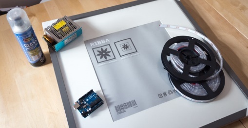
- 10 m LED strip (sold in 5 m coils). I used the cheapest option - WS2812B. If you want to get a higher resolution display, you can purchase a tape with a density of 60 LEDs / meter;
- power supply for 5 V and 10 A. I used a model in which the input power up to 240 V is fed to the screw terminals. If you need to make the display safer, choose a fully enclosed power supply;
- Arduino UNO ;
- a large number of pieces of thick wire. I cut the bundle from the old computer power supply;
- photo frame 50x50 cm;
- matting spray and white paint.
Total costs I got less than $ 100.
You will also need tools:
- soldering iron with solder;
- glue gun;
- a knife or scissors;
- stripping tool.
First read the manual for working with electronics for beginners !
Calculations
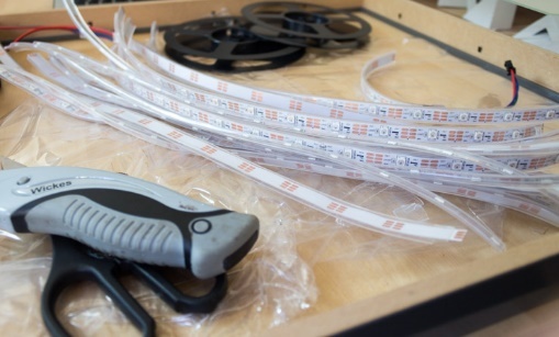
If you purchased a 50x50 cm frame and the same LED strips as mine, you can fit 15 segments of 15 LEDs into the display. But nothing prevents the use of a frame of a different size. The distance between the LEDs is about 30 mm, so about 30 mm 2 per pixel . This is our 1DPI . Well, yes, the resolution is not like Retina.
Calculate how many pieces of tape you need and draw guides on the back of the panel. Check seven times, cut once: my tapes are slightly different, because when I started to glue them, I found that I can only hold 14 pieces of 15 LEDs. But it's not scary - in the application, you can easily configure a different number of rows of pixels and their length. Cut pieces suitable for your frame. Unfortunately, I found that my 15th LEDs in the segments fall exactly at the place where you need to solder the connecting wires. Therefore I had to unsolder them.
Glass matting

For better light scattering, I decided to apply a matting spray on both sides of the glass. Do it better on the street or on the balcony, because the spray is harmful to health. It should be applied as evenly as possible. After drying, the matting is very stable, but initially it is necessary to achieve a uniform coating without any scratches.
Also blow out the white paint panel, which will be visible through the glass. Cut one of the corners - there will be wires.
LED strip mounting
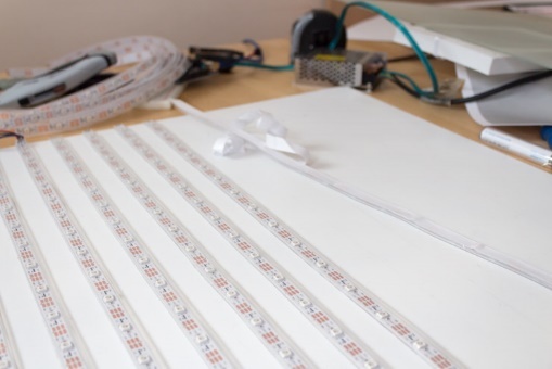
To glue tapes to the panel, use superglue. I tried double sided tape, but after a few weeks it fell off. The glue gun is even worse, because both surfaces — the panel and the reverse side of the tape — are smooth and have no pores. If you purchased LED strips in a rubber case, then do not worry too much about the accuracy of placement - they can be freely moved.
Remember that the signal will pass through the entire circuit, and each tape has a direction of signal transmission. Tapes should be placed like this: with one arrow (the direction of the signal) points to the right, with the next one - to the left, then again to the right, etc. That is, the signal on the display will go "snake". Check the correct placement of the tapes before gluing them!
Soldering
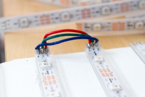
To connect the tape requires three wires of different lengths. We connect the inner pair of contacts with the shortest wire (red in the photo), take the longer wire for the middle pair, and solder the longest to the outer contacts. Depending on which tapes are currently connected, the internal contacts will either be powered (+ 5V) or grounded (GND).
Before soldering wires, tin them and the contacts themselves on the tapes. It will take the most time, but this is an extremely important point. Take your time, double check the correctness of the connected contacts!
Fixing tapes
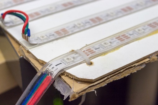
After messing around with connecting wires, you may find that the first tape has moved. I solved this problem as follows: I drilled two small holes and fixed the tape with a tie. If you didn’t have a strong enough glue on hand, then you can additionally fix all the tapes at both ends.
Connection check
The sixth pin of the Arduino is used to transmit the control signal; The supply voltage must be supplied directly from the power supply. Connect the ground between the tapes, the Arduino and the power supply. Do not try to power the tape from the Arduino, and do not connect the power supply to the Arduino when the USB is connected (when the code will be downloaded for testing).
Download and add the AdafruitNeoPixel library to the appropriate folder , then launch Arduino. Test the connection using the following code, specifying the number of LEDs in the first parameter (60 in our example):
Adafruit_NeoPixel strip =Adafruit_NeoPixel(60, PIN, NEO_GRB + NEO_KHZ800);If the animation stops on a row, immediately disconnect the whole structure and check the connection. Possible causes of failure:
- wrong tape direction;
- you confuse the contacts when connecting tapes;
- You soldered + 5V to GND.
Framed
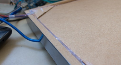
Since the frame was not designed for such a depth of placement of the panel, I had to first fix the glass with a glue gun, and then insert a rubber seal along the perimeter that works as a buffer between the glass and the panel with LEDs. After the final testing we place the panel in the frame and fix it with a glue gun. In the corner you can make a small hole for the output wires. That's all, the technical side of the project is complete.
You can even think about whether it is possible to hide in the frame also a power supply with Arduino. In the meantime, proceed to setting up the software.
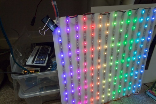
Glediator
Program Glediator company SolderLab.de very well suited for animation LED arrays at parties or nightclubs. It is able to control a matrix consisting of 512 WS2812 / NeoPixels LEDs, forming up to 24 frames / sec - this is quite enough for our display, you can even display simple animation gifs on it. The mixer will allow you to make smooth transitions between animations.
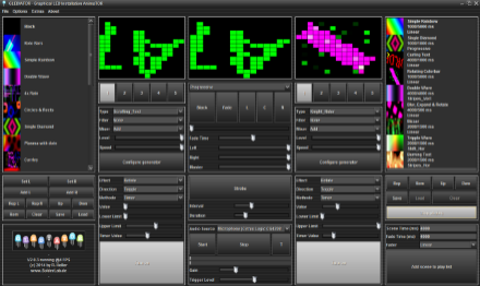
To work with Glediator, install the Arduino UNO firmware , and check that the signal cable is connected to pin 6. Do not forget to write in the variable the number of LEDs you use.
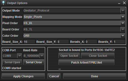
Launch Glediator, open the properties and change the matrix size and output mode . Adjust pixel orderif you have a different scheme, but there is little documentation for this step, so you have to act by trial and error. If the image on the display is different from the intended, try to play with the settings. I worked the order of pixels HS_BL - I suspect that this means " h orizontal s nake, starting b ottom l eft" (horizontal snake, beginning at the bottom left).
Glediator is a professional application, so far we will not study its interface and features. Load different animations into the left and right windows, then move the mixer between them. Or use a ready-made playlist, which is shown in the video.
Adafruit NeoMatrix and Adafruit GFX Libraries
Adafruit has created a very useful library for working with LED matrices. At first it was called Adafruit GFX , and was originally intended for TFT and LCD displays. Then a modification of NeoMatrix appeared , allowing to fully work with the NeoPixel matrices. It has a huge number of easy-to-use functions for text output or raster sprite graphics.
If you exactly repeated my project, you can use this code . The most important part:
#define XSIZE 15
#define YSIZE 14
#define PIN 6
Adafruit_NeoMatrix matrix =Adafruit_NeoMatrix(XSIZE, YSIZE, PIN,
NEO_MATRIX_BOTTOM + NEO_MATRIX_LEFT +
NEO_MATRIX_ROWS + NEO_MATRIX_ZIGZAG,
NEO_GRB+NEO_KHZ800);
Everything is clear with the first lines. In the last three, the matrix is described: in this case, the first pixel is at the bottom left (bottomleft), the pixels are arranged in rows (rows), connected in a zigzag manner (zigzag). If you did otherwise, consult your library documentation.
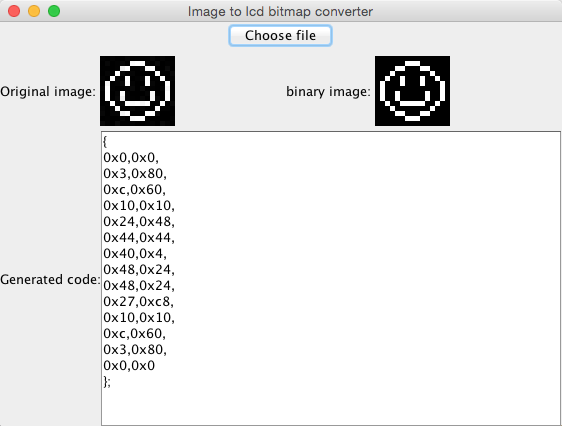
I set in the code a few sprites - smiles. You can create your own using the Img2Code Java application , which is located in the GFX library folder.
In the future, we will consider using the library to display useful information such as stock quotes or Twitter feeds, but for now I suggest you play with the code yourself and upload your own images.
That's all. You have created a large display of LED strips. Now you need to figure out how to use it. From the remaining LEDs you can create a lamp in the form of a cloud .