Laser cutter with your own hands. Part number zero. Power
At one time, I very much wanted to have a CNC laser, not that it was very necessary for work or a hobby, but nevertheless the thing is useful in the utility workshop, and it's cool!
The Internet is full of articles about how to break the old Devician pisyuk and take out a diode, insert it into a carriage such as the old 5 "floppy disk drive. This is certainly cool, developing and easy. But it's boring and also absolutely useless. I decided to collect something something that could be used for work, or at least it was fun. And having packed up to a maximum of 150 bucks.
And so, since the well-known political events led to the fact that it was not profitable to use aliexpress, I had to throw a cry by familiar ministers of science and simple about strange personalities. And not for nothing, after some time, as a result of a barter transaction, from one strange person I got this:

LGN-703, CO2 laser with about 60 watts of output power, a healthy fool with water cooling and almost two meters long. He was impressed with me by his size, as a person holding a maximum of Chinese green laser pointers at the time.
Unfortunately, there wasn’t any intelligible documentation on it in the network in principle, so I had to improvise. Approximately comparing in size with his Chinese counterparts, it was assumed that this pipe has an output power of about 60 watts, for operation it requires 25 kV at least for ignition - about 35. And based on the average efficiency of carbon dioxide lasers at 10 percent, for output to the calculated power he needs to eat something around 25-30 mA.
And so, there are two ways of making the power supply:
1) Big Iron Transformer. Of the minuses - firstly a good anodnik is not so easy to find - in the Soviet Union for some reason they were piece products and often of very bad quality, so they were the first to burn out. Alternatively, you can use transformers for neon advertising (there are instances of 10-15 kV and 60 mA), connecting their secondary windings in series (Caution! The secondary winding of each NST has a grounded midpoint on the body!), But this is a collective farm “60 years without Chairman "as he is - these trances are never designed for such barbaric use and can easily burn themselves, shorting the primary and secondary windings into one. Secondly, for ignition, you still have to use a full-wave multiplier, and since this is a 50 Hertz network, the capacitors will be large (all there are K75-25 and similar 40-50 NF per shoulder). Thirdly, if you want to control the beam power, you will still have to collectively cumbersome thyristor circuits. Of the benefits - it is cheap and cheerful. The old NSTs will be given to you almost for nothing (by the way, yes, a good NST is a heavy NST), you can also save on rectifier diodes (any slag of the type 2C202 and the like goes).
2) SolidSteyt. Of the minuses - it can fly into a pretty penny, especially if you buy all the parts in ChipDip and you don’t even have a grandfather oscilloscope. Dya, there were half-bridge bricks - they became silane. Well, after N sets of killed drivers and mosfet \ igbt transistors, you will still read datasheets and other clever literature (although this is rather a plus) Of the obvious advantages, this is compact, powerful and interesting.
Perhaps we will dwell on the second paragraph in more detail.
And so, now it is necessary to determine the topology of our inverter. A full bridge means too much soldering, and the probability of an error is twice as large. Any kind of two-stroke autogenerators (push-pool there for example) is too low efficiency and a high probability of messing up (well, it didn’t work out for me with them, it didn’t), But the half-bridge is stylish, fashionable and youthful! We will shake the fets with the IRFP460, even though they have a rather “heavy” shutter. And we will drive it of course with the help of IR2153! Firstly, due to the fact that there is no need to solder a lot, and secondly, this is a universal answer to the question: “But why did it explode for me ?!”. After some time of digging manuals and reading tons of senseless delirium at flyibek.org.ru, here was born this decl remade scheme of one local gentleman “Seriyvolk”.
Vorning! Alarm! Attension! High currents walk along the circuits, high voltage is present (tens of kilovolts). Watch for yourself, be careful! The author does not bear responsibility for innocently killed pets, punched by flying capacitors of the head and severed fingers.
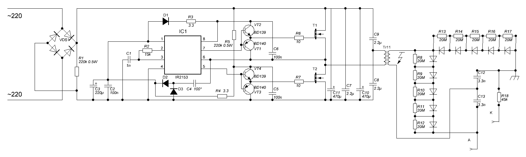
The operating frequency is about 40 kHz. The capacitors in bootstrap are film (although tantalum / ceramics is better, but it also seems to work), in the RC chain it is ceramics.
D1, D2, D3 here - HER208. Power Vcc IRki and repeaters in the key management chain is organized by bootstrapping ( read more about what it is and what it is eaten with ), C4 should be chosen in the range from 500 to 1000 pF.

Download the mirrored layout of the tracks.
My june padawan (in), if you are not strong, clever and skillful, then do not assemble such schemes on dummies / woods / cartons.
Transformer - core from lineage (well, or maybe you have better and more massive ferrite), primary - 28-30 turns with litse wire from 0.5 mm in diameter (at least, ordinary stranded wire will come off), secondary material - to taste.
Hint - you should not experience luck and first of all poke a new device directly into the outlet, first you need to make sure once again that everything is assembled / soldered correctly and conduct full-scale tests.
For a start, it is worthwhile to run the inverter at reduced voltage, but since the Vcc IR power supply is designed for 220 and at 40-50 volts it simply does not start, then you should apply separately +12 volts to the point between the D2 and D3 diodes. What it is worth checking is the no-load current (we remove the secondary winding from the transformer, leave only the primary and, for example, stick a light bulb in series with the inverter)
Heating the mosfets - on the x.x. it should not be at all.
Well, poke the oscilloscope is perhaps that the keys and terminals of the primary winding. After all, we all know that the oscilloscope included in the network should not climb into the device without galvanic isolation? :)

On the shutter lower key.

On the primary winding.
What should be on the gates - more or less even meander. What should not be - "needles", equal to about 1/3 of the useful signal. In that case, if the induced voltage opens the lower shoulder gate, when the upper one is open, a through-breakdown will occur and the capacitor will merge into the formed goat with its entire capacity, break the feta, most likely killing the IR and burn the tracks on the board. How to deal with this is to try to make the shortest possible tracks, to tie up mosfets with film capacitors, to use suppressors, etc. In general, the topology of half-bridge / bridge power inverters is the subject of a separate article and such articles have already been written on a car and a small truck. If you have problems with debugging, for example, for a start I advise you to read the datasheet on IRku.
In the doubler on the high-voltage side, it is worthwhile to shove either a large bundle of 1n4007 or high-voltage D5000 (as it turned out, although they are not considered “ultrafast,” but they work for themselves at such a frequency). They should definitely be shunted with resistances of tens of mOhm, you can still hang them with leveling condensers, but this is to calm the soul.
With cooling, everything turned out much easier - a healthy flask of Kip apparatus was found in the bins of the homeland, silicone hoses for the aquarium were bought in the nearest pet store for 300 rubles , and in the auto parts store - the washer pump from the basin, like a cornfield.
The first thing that burned out is a self-made multiplier (compound diodes are always tied up with shunt resistors). But, the laser itself is quite wound up from the usual television UN9-27, of which I still had two or three pieces.

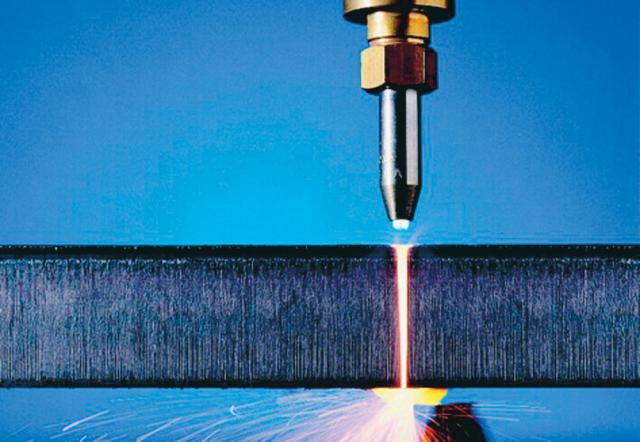
Although it consumes 1/4 of the required power from the power and the discharge is barely visible, it burns! With an unfocused beam, the chipboard ignites and burns plywood (I’ll just keep silent about paper).
See in the following series:
- finishing the power supply unit with brief explanations “how the half-bridge inverter works” and “what I did wrong this time”, manufacturing and filling the block voltage doubler, assembly in a neat case and an attempt to organize electronic power control (on IR, dy).
- production of a two coordinate beam positioning system from an ancient scanner and some kind of mother. Attempts to attach to this mirror so that they can be reduced.
- pogromirovaniya microcontrollers.
And a lot more interesting and entertaining, so do not switch.
PS Oh yes. To the issue of safety. Since the laser radiation lies somewhere in the region of 10,600 nm, it does not pose a particular danger to the eyes (or, to be more exact, not more than for any other open areas of the body with thin skin / mucous membranes) - when the eye hits the focused beam at full power he is likely to leave a small burn on the back of the skull :)