How we implemented SD-Access, and why it was needed
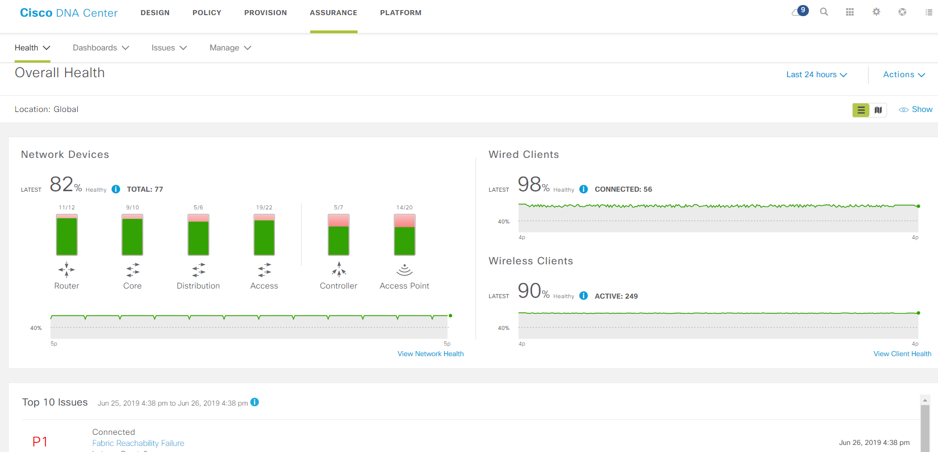
The main monitoring page.
SD-Access is an implementation of a new approach to the construction of local area networks from Cisco. Network devices are combined into a factory, an overlay is built on top of it, and all this is controlled by the central component - DNA Center. All of this has grown from network monitoring systems, only now a mutated monitoring system does not just monitor, but collects detailed telemetry, configures the entire network as a single device, finds problems in it, offers solutions to them and, in addition, enforces security policies.
Looking ahead, I’ll say that the solution is rather cumbersome and at the moment non-trivial in terms of development, but the larger the network and the more important the security, the more profitable to switch to it: it greatly simplifies management and troubleshooting.
Background - how did we decide on this?
The customer moved to a new newly purchased office from a rented one. They planned to make the local network according to the traditional scheme: kernel switches, access switches, plus some familiar monitoring. At this time, we just deployed a stand with SD-Access in our laboratory and managed to find out a little solution and undergo training with an expert from the French office of Cisco who visited Moscow very opportunely.
After talking with the vendor, both we and the customer decided to build the network in a new way. We saw these advantages:
- SD-Access should simplify the operational routine - setting up ports and access rights for connecting users. In the new solution, these settings are made using wizards, and the port parameters are set in the obvious form in relation to the Administrators, Accounting, Printers groups, and not to VLANs and IP subnets. It’s easier to understand, it’s more difficult to make a mistake. For the customer, this simplification is important because his IT competence center is located in Siberia, and the office we raised is located in Moscow. The Center is overloaded with complex tasks and works according to its time zone, therefore, the more network maintenance tasks the specialists can solve on the spot, the more time the Center has for expert work.
- Due to the new architecture, some on-site network task tasks that the Center previously dealt with will also be possible to perform on site. For this, their own wizards and telemetry data and paths of traffic through the network in an understandable form are provided. If you have complex problems, you still have to delve into debugs, but minor problems are much more often solved "on the spot" with less knowledge.
- It is important for the customer to ensure security: the ideology of SD-Access involves a clear separation of users and devices into groups and the definition of interaction policies between them, authorization for any client connection to the network and ensuring “access rights” throughout the network. The IT department is getting used to planning and maintaining the network in the spirit of this ideology. In another way, it will be inconvenient to administer the system; if you follow the right approaches, then administration will become easier. In the traditional network, on the contrary, configs grew and became more complicated, and it became more difficult to maintain them.
- The customer will have to update other offices scattered throughout the country. If you introduce SD-Access there, then the strength of the previous two points will only increase.
- The startup process for new offices is also simplified thanks to the Plug-and-Play agents in the switches. You don’t need to run along the crossroads with the console, or even go to the object.
We saw the flaws only later.
Planning
Estimated the top-level design. The planned architecture began to look like this:
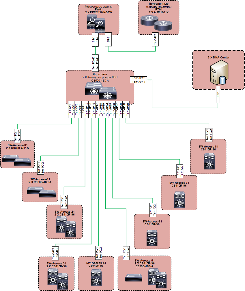
Below this is an underlay built on familiar protocols (the basis is IS-IS), but the idea of the solution is such that we should not be interested in the subtleties of its work. Overlay is made on LISP and VXLAN. The logic of the solution implies the preferred use of 802.1x authentication on access ports. However, the customer intended to use it without fail for everyone initially. You can do without 802.1x and configure the network almost “the old way”, then you need to configure the IP address pools manually, and then again, with your hands on each port, specify which IP pool it belongs to, and make Copy-Paste, as before on the command line, it doesn’t work, everything is only through the web. With this approach, the pros of the solution turn into a fat minus. Such a scheme can be applied only where it is inevitable, but not on the entire network.
We ordered equipment and software, and while everything was moving, they began to “land” the design in order to understand what we were going to configure. Here they faced the first difficulty: if earlier it was necessary to coordinate IP subnets and a set of VLAN numbers with the customer so that it was integrated into the schemes adopted by him, then now all this did not interest us: it was necessary to understand which user groups and devices are used network, how they interact with each other and what network services they use. Unusual for us and for the customer. Obtaining such information was more difficult. At first glance, it was from such data that it was always necessary to start from the design of networks, but in practice the standard VLAN set was almost always laid down, and then reality was pushed into it during the operation by the callused hands of admins. There is no choice in the SD-Access paradigm:
Timing was shrinking, equipment pulled up. It was necessary to configure.
How we implemented it
The network implementation process differs from the old schemes even more than the planning process. Previously, an engineer connected devices to each other, set them up one after another, and received one after another working network segments. With SD-Access, the implementation process is as follows:
- Connect all network switches together.
- Raise all DNA Center controllers.
- Integrate them with ISE (all authorization takes place through it).
- With DNA Center, turn network switches into a factory.
- Describe the switch roles in the factory (Edge Node, Control Node, Border Node).
- Configure endpoint and user group networks and virtual networks on DNA Center.
- Set up rules for interaction between them.
- Crash device groups and rules into the factory.
This is the first time. Moreover, DNA Center for initial deployment requires DNS, NTP and access to the Cisco cloud to download updates (with a Smart Account). On our implementation, it turned out that DNA Center is very fond of updating during the initial installation: it took about two days to bring all its components to the latest versions, although it happened mainly without our participation.
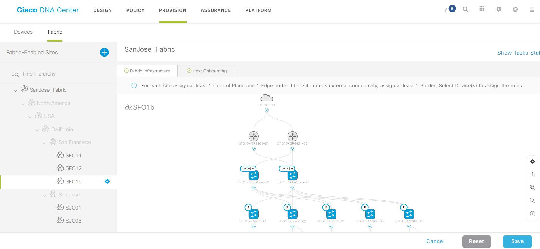
An example of an assembled factory.
When DNA Center is already working to raise a new office, it is enough to repeat steps 1, 4, 5 and 8. Thanks to the Plug-and-Play Agent, the new switches receive DNA Center addresses via DHCP (option), take preliminary configs from there and become visible in DNA Center management interface. It remains to paint their roles (Egde / Control / Border), and the new factory is ready. Device groups and policies on it can use the old ones.
Of course, when faced with such a process for the first time, it is difficult to understand which side to approach it. In addition, along with the SD-Access paradigm and related products, Cisco has generated so many new terms and definitions that it will make it possible even for the experienced CCIE to feel young again. Here are the main ones:
- Scalable Group - groups of devices with similar access rights to network resources: the same “Administrators”, “Accounting”, “Printers”, etc.
- Virtual Network - an isolated L2-L3 segment, which includes groups of devices. Essentially VRF. It is assumed that communication between such segments will occur through a firewall. It makes sense to divide groups into such virtual networks in cases where maximum access control is necessary, for example, you can select three different Virtual Networks for a video surveillance system, office employees and its guests.
- Access Control Contract - rules for network interaction between groups.
- Control Plane / Edge / Border / Intermediate Node - different types of switches in the DNA Center factory depending on their functions: Edge Node - connecting users; Control Plane Node - providing monitoring of client connections, the work of LISP Map-Server and Map-Resolve; Border Node - communication with external networks; Intermediate Node - intermediate switches, an analog of the Distribution-level in traditional networks.
- The role of the device on the network (Device Role) is how the DNA Center imagines the role of the device depending on what connections it sees: Access, Distribution, Core, Border Router or Unknown. This attribute can be useful, for example, when determining the recommended version of IOS: you can assign different recommended versions for access switches and kernel switches if the series of switches is the same.
In general, concepts should be properly taught both for those who implement and those who will exploit it. From ignorance, the implementers will drag out the time, and then the admins will drop KPI. So you can stay without bonuses. Well, the distrust of the customer’s leadership in the chosen solution is generally a problem for everyone.
With the introduction due to the fact that the customer had to call in a new office, we went according to the following scheme:
- We created one group and one virtual network for all in OpenAuth mode without forced authorization, only connection logs.
- Admins connected workstations, printers, etc. to the network, users moved to a new office and started working.
- Next, one user was selected, which logically should belong to another group.
- We set up this group and the policies of its interaction with other groups at DNA Center.
- We moved the user to this new group and turned on ClosedAuth with authorization for him.
- Together with the customer’s specialists, they identified access problems that a user had and adjusted the contract settings (policies for interaction of his group with others).
- When they were sure that the user was working without problems, they moved the rest of the users who should belong to her group to his group and watched what was happening.
Next, items 3 through 7 needed to be repeated for new groups until all users and devices connected to the network were in their groups. When working in OpenAuth mode, the client device attempts to log in. If the outcome to the port to which it is connected is successful, the settings corresponding to the group to which this device belongs are applied, and if it fails, it falls into the IP Pool pre-configured on the switch port - a kind of rollback to the traditional mode of operation of the local network.
Of course, as with any new product, we spent many hours updating software and identifying bugs. Fortunately, Cisco TAC helped with this quickly. One morning, going to the DNA Center web interface, we discovered that the entire network was lying. At the same time, not a single complaint from users: the office works while drinking morning coffee. Rummaged through the logs, and it turned out that there was a problem with SNMP, by which DNA Center receives information about the state of the factory. The network is not visible, but it is. The exception of part of OID from polling helped.
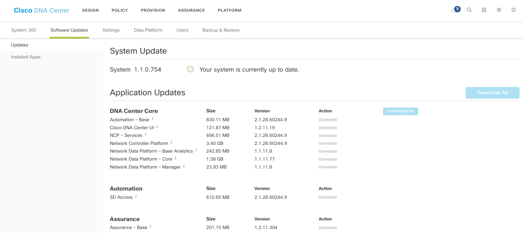
Page with component versions.
How to exploit it?
DNA Center collects a bunch of useful data from SNMP, Netflow, and Syslog from the factory and knows how to present it in an understandable way. This is especially useful when solving floating problems like "something yesterday, many telephony fell off, although now it seems to be normal." You can crawl through Application Experience data and try to understand what was happening. So there is a chance to fix the problem before it “flies” the next time. Or to prove that the network had nothing to do with it.
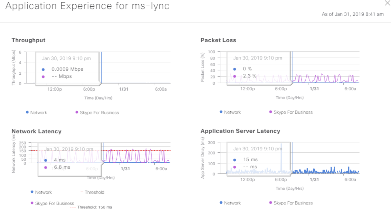
Application performance data.
For many of the problems that DNA Center shows as Alarm, it tells you where to dig.
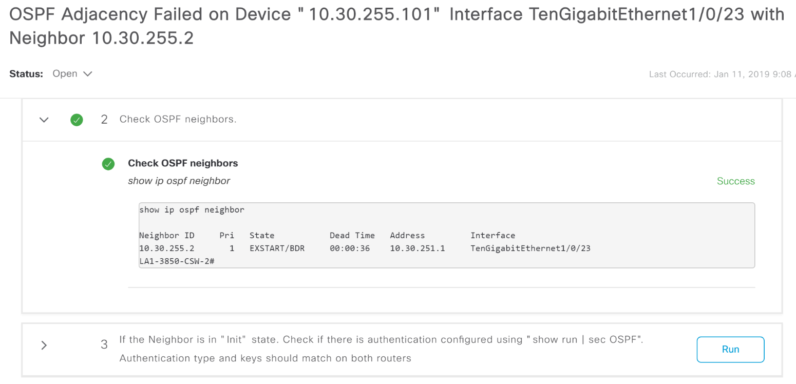
Example OSFP Adjacency crash report with a hint on what to do.
Routine analysis has become easier. For example, if necessary, you can quickly track the path of traffic over the network without climbing devices one by one. With authorization through ISE, the DNA Center picks up and displays the names of customers, including on a wired network: no need to climb in search of an IP address.
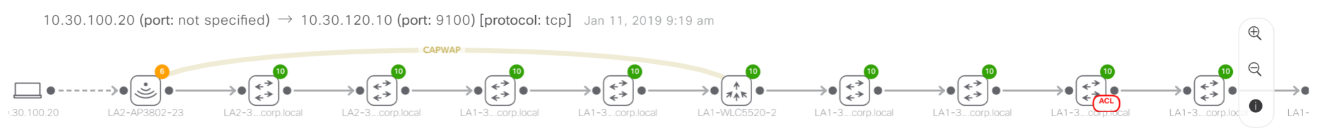
An example of tracking the path of traffic through a network. A red mark on one of the devices says that traffic is blocked on it by an access control list.
You can quickly see which network segment is affected by the problem (the switches in DNA Center are broken down by location, site, and floor).
A “gamified” indicator of the quality of life of applications on the network as a percentage allows you to superficially assess the state of the network and see if it gets worse over time.
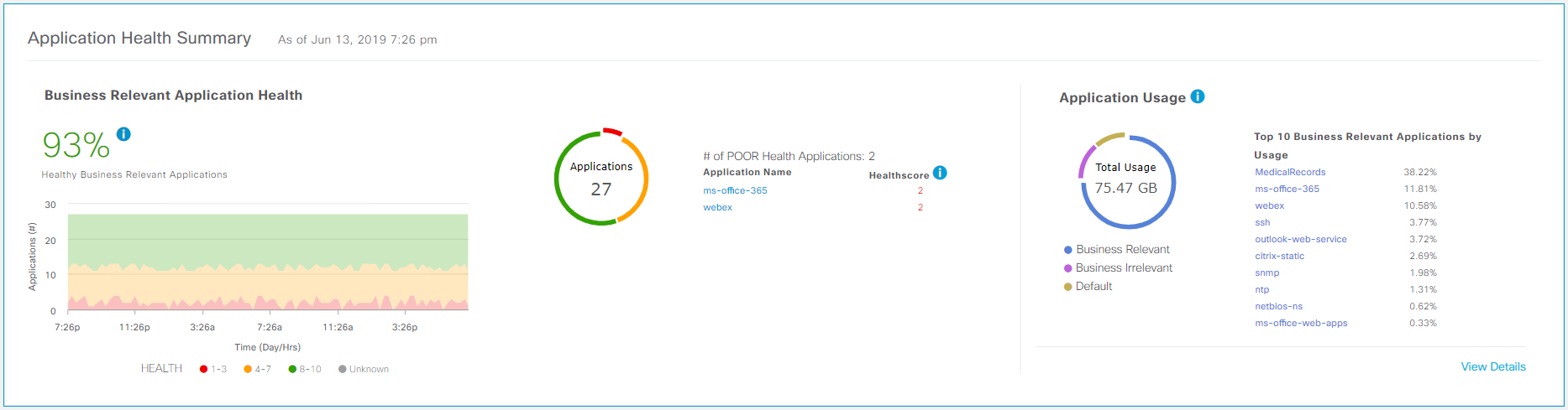
An indicator of the quality of life of applications.
As before, Prime Infrastructure also provides software version control on network devices. DNA Center maintains its own repository where images can be uploaded either manually or automatically uploaded from Cisco.com, and then deployed to devices. In this case, you can program and run scripts to verify the correct operation of the network before and after the update. A standard precheck script, for example, includes checking the availability of free space on a flash, the status of confi-register, whether the config is saved. Software patching is also supported for devices that can do this.
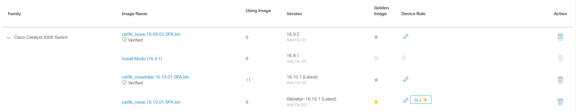
Software repository at DNA Center.
And, of course, there is still access to the command line of network glands.
Total
The product is new, new approaches can be introduced, however, carefully. Due to the novelty of the code, there are bugs in the work, but Cisco technical support responds promptly, and developers release updates regularly. Due to the novelty of the network management approach, the probability of errors in the early stages of operation is rather high, but gradually admins get used to it and there are fewer errors than with the support of a traditional LAN. It’s worthwhile to think about how to test and run everything into parts of users, and then distribute it to everyone (although with experience you understand that it is useful when implementing any IT solutions, even the most understandable and proven).
What is the use? Automation, acceleration of standard operations, reduction of downtime due to configuration errors, increasing the reliability of the network due to the fact that the causes of a network failure are known instantly. According to Cisco, the IT administrator will save 90 days a year. Separately, security: with the Zero Trust approach, an epic problem with a subsequent hit in the press can be avoided, but this, for obvious reasons, few people appreciate.