Amplifier to the classic heart rate sensor
- Transfer
- Tutorial
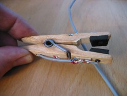 The proposed amplifier is designed for one of the most classic heart rate sensors - optical. The same “clothespins” on the earlobe or finger, as in some simulators. Only here the clothespin is not in quotation marks, but the real one. Wooden. 3-mm holes were drilled in it, in which the SFH487 IR diode and the SFH309FA phototransistor from Siemens were placed. Instead, almost any IR diodes and phototransistors are suitable, only the holes will have to be drilled in other diameters. To use the sensor it was comfortable, soft pads with holes are glued to the surfaces of the clothespins adjacent to the earlobe or finger. If the pulsating light of LED or fluorescent lamps interferes, the phototransistor must be closed with a filter that allows only IR transmission.
The amplifier circuit is shown below:
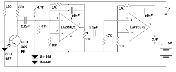
The phototransistor is loaded on a resistor, the variable component of which is fed through the electrolytic capacitor to the first op-amp. The signal from its output through the controller on a variable resistor and the second electrolytic capacitor is fed to the input of the second op-amp, and from its output, in turn, to the oscilloscope, the analog input of the microcontroller, or the comparator to which the counter is connected. Each opamp provides a gain of about 100; they can be of other suitable types.
Since the power supply is unipolar, the signal common wire of both op-amps had to be “raised” above the common wire of the entire device with the simplest parametric stabilizer from a resistor and two diodes. The total voltage drop across the diodes is about 1 V. The improvised bipolar source turned out to be asymmetric, but for an op amp it is even better than a unipolar one.
If you are going to conduct an experiment by connecting the amplifier to a storage oscilloscope, configure it so that it makes 500 records with an interval between them of 20 ms. Wait about 10 seconds to set the thermal mode of the circuits, and set the variable resistor located between the first and second op-amps so that the pulse amplitude is about 2 V. Adjust the sensitivity of the oscilloscope so that the pulses fit vertically on the screen and start recording. While the oscilloscope is recording, do not move your ear or finger.
If the oscilloscope has a sound indication (as in Picolog, which the author used), you can configure it so that the signal sounds at an amplitude of more than 1 V. Then you will hear your pulse.
After recording, to calculate the heart rate, subtract the absolute time of one of the pulses from the absolute time of the previous one, for example, 2190-1052 = 1138 ms, or 1.138 s. Divide 60 / 1,138, you get 52.7 beats per minute.
When using an impromptu software oscilloscope using the audio input of a smartphone or computer, you will need a sound generator modulated by pulses in amplitude.