Underwater GPS on an Underwater Robot: Experience
Hello dear habratchitel!
Not even four years have passed since the first working model of our underwater GPS saw the light , since then weate a pound of salt and made a whole heap of various systems and devices, but by the will of fate, one important test has so far bypassed our firstborn. In this article I will tell you how it went.
Everyone who is concerned about the topic of underwater robots, their control and navigation - welcome to the cat on our frozen kayak in the April waters of the Volgograd reservoir!
(Akhtung! There are a lot of photos under the cut!)
For those who don’t have time to read at all, I’ll briefly describe the problem:
GPS doesn’t catch under water and the radio doesn’t work, almost all navigation is done using acoustics, and communication is done using acoustics, cable, and quite often in clear water help of the light .
For the newcomers, I will traditionally provide links to our previous publications on the hub, where we tell everything about underwater communications and navigation: from the history of creating our underwater GPS and transmitting “video” sound through water and to instructions on how to make a simple hydroacoustic antenna from garbage:
- Underwater GPS from scratch in a year
- We made the world's smallest sonar modem
-To the question of the influence of cyanobacteria on the president’s speech functions
- We make a simple hydroacoustic antenna from the garbage
- Session of video sound transmission through water with exposure
- Underwater GPS on two transceivers
- Navigation under water: do not detect bearings - you are doomed to success
- Underwater GPS: continued
to fly and ride, crawling along the ground, and floating on the surface of the drones transmit video from their cameras in real-time, and sometimes a GPS-coordinates, and the operator always knows where his unit, moreover, often oper p can see it.
With underwater vehicles (TNPA or ROV), everything is somewhat different. Letting the device go into dark waters, you can be sure of only one thing - it is definitely under water.
Devices come in different classes, dividing by size and task. The simplest and smallest (like ours), inspection ones are just a video camera on a cable with motors. More complex and larger ones can be equipped with manipulators and other interesting devices, some specimens the size of a gazelle come complete with a specialized vessel,pirates and a boarding crew and have a total capacity of more than 200 hp. Cable lengths can be from tens to hundreds of meters in small devices and reach thousands of meters in major large devices.
Nominally controlled by ROV vizulnoy feedback - depending on the image transmitted from the camera via a cable system, sometimes equipped with sonar, as sometimesalwaysthe water is cloudy.
This approach has exactly one drawback: seeing in the monitor an image of a landscape element of interest, it is absolutely impossible to say exactly where it is located.
They are struggling with this drawback using acoustic positioning systems. As a rule, they put a pinger (periodically emitting a special signal) or a transponder beacon on the device. The pinger signal is detected, the distance is determined, and then, by the angle (or two angles - horizontal and vertical) of the signal arrival and the distance, the location of the device is determined. Such systems are called UKB (short for Ultrashort-Base). They relate to goniometric-rangefinder and have a whole list of disadvantages, especially with regard to this task. The simplest foreign ones cost from 17,000 euros , ours are also there , no worse and more affordable, but still not for free.
To determine the horizontal (and in old systems and vertical, in new pinger transmits its depth) angles of arrival of the signal of the respondent or pinger, a direction finding antenna is needed. The device itself is not simple and requires installation on a rod, which must be mounted on a ship. By the range, depth and horizontal angle (or by range and two angles), only the relative position of the apparatus is determined. In this case, the accuracy decreases with increasing distance.
The accuracy of determining the angle depends on:
After the distance and the angle of arrival of the signal are determined, you need to tie all this to geography. That is, you need to know the geographical position of the direction-finding antenna and the direction of its zero relative to the direction to the north. Then you can solve the direct geodetic problem and determine the position of the underwater vehicle in geographic coordinates. That is, you must still have a compass and GPS on the antenna.
In general, I am convinced that UHF should be applied only where it is completely impossible to use long-base systems. I emphasize - absolutely.For example, when a towed object is positioned, and you need to go a very long distance. In this case, it will be necessary to move the elements of a long base very often and this will lead to the cost of too much time and effort, or, another example, it will be impossible to install buoys of a long base on the surface due to the great depth - very long ropes and, in general, the anchoring scheme greatly complicated. In all other cases, I conjure you: use a long base - it's easier, more reliable and more accurate.
UKB is good and indispensable where you need to find something, gradually approaching and increasing accuracy. It may seem that I am against UHF and for DB, but I'm just calling for the use of equipment according to its intended purpose. In the end, we also did the KGB, and in light of this, it is difficult to accuse me of bias.
Long-range (DB) systems - this is when there are several far-spaced receivers or transmitters (for example, GPS is a long-range system). They maintain their accuracy inside the base, they are much less susceptible to pitching and generally provide much better results, as they relate to either rangefinder or difference-rangefinder systems.
For a long time I could not answer the question - why is everyone trying to hammer nails with a shovel? But over time, my colleagues and I came to a disappointing conclusion: firstly, people think very simply - one antenna and one pinger is easier than several elements of a long base that are far apart from each other. Secondly, until recently, DB systems were represented only by the so-called bottom base, the installation of which requires very serious time and money.
We have long been in a crusade against theilliteracy of users of the established order of things. Which began when we made the very first example of our underwater GPS, which is a long-base system with a surface rather than a bottom base.
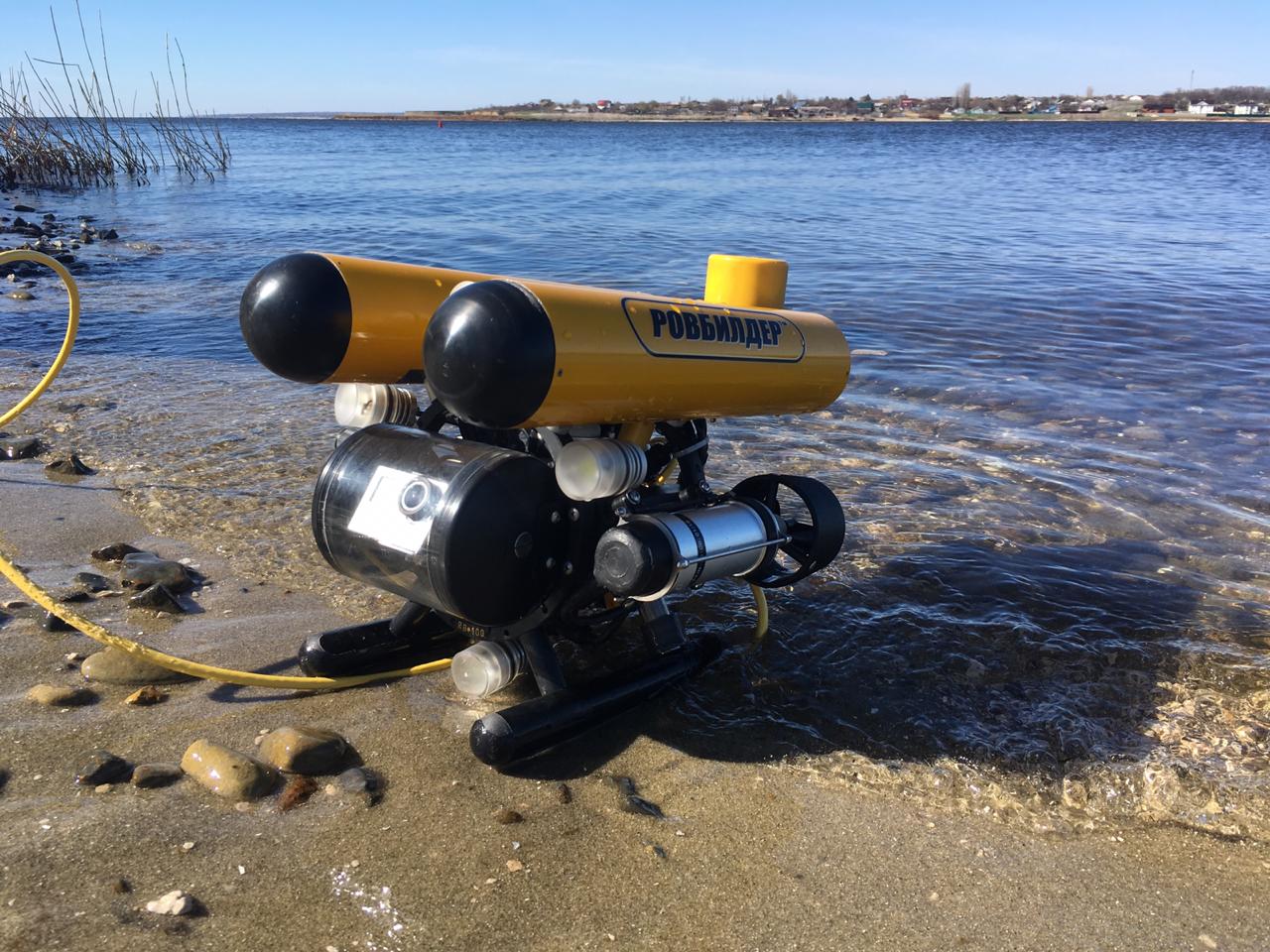
Let's get back to the hero of today's test. The navigation system is represented by the navigation base itself, which is formed by four floating buoys-repeaters of the GNSS signal:
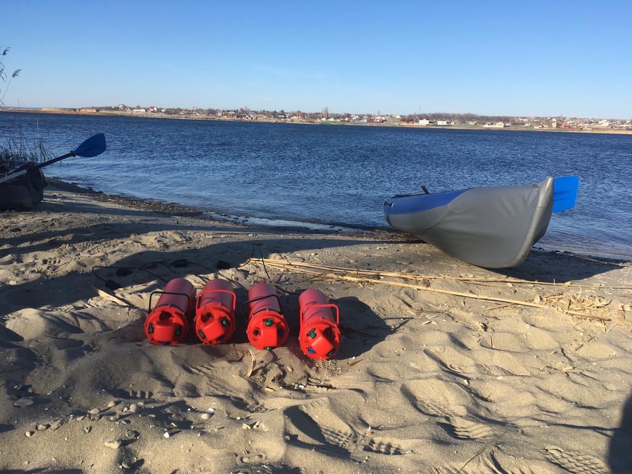
Before the start of work, buoys are installed on the water body using anchorstones and a rope. All that needs to be done is to release the buoy at anchor, before that clicking the switch. That is really all that needs to be done.
Another element of the system is the navigation receiver located on the underwater object: The RedNODE
navigation receiver (small yellow cylinder) is installed at the rear of the device. It is powered by the on-board network of the robot and transmits data through the device’s cable.
Since the buoys only emit, and the receivers only accept (operate according to the differential-ranging scheme) and no one bothers anyone, then on one set of buoys in one water area, any number of such receivers can work. That is, theoretically a whole fleet of underwater vehicles and divers in any quantities and proportions can theoretically navigate.
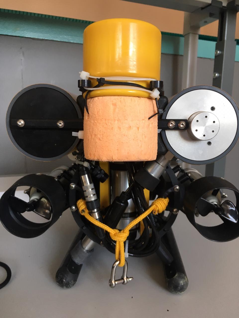
Due to the rush, we rather casually pinned up the navigation receiver and added some buoyancy made of dense heat-insulating material.
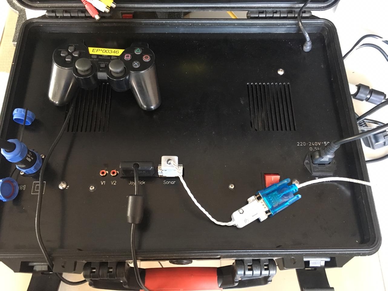
Data from the receiver enters the control case and is entered into any laptop via the RS232 <-> USB converter (“Sonar” connector in the photo).
The coordinates in this system are generated at the receiver (i.e., strictly terminologically, the system is a navigation system and not a positioning system). But since the TNLAs operate on a cable, in principle, there should be no problems in transferring the location calculated on the device to the cable upward. By the way, the navigation receiver emulates a regular GNSS receiver and can be directly connected as the most ordinary surface GPS receiver, for example, to the SAS.Planet application , which we do.
The positioning of underwater robots was the main idea that captured us back in 2015, when we started developing our underwater GPS. The irony of fate is that it was this application that remained unclaimed until 2018 - the system was mainly used in diving performance.
This is partly due to the fact that TNLA manufacturers are very reluctant to modify their devices, partly due to the fact that users have a very strong prejudice that placing buoys is difficult and time consuming.
Now the apparatus of the examination class is being done by all and sundry, literally, we have already lost count. Here is a far from complete list of manufacturers for clarity:
- The whole TOP-10 2019
- And another TOP-12 2019
- And even another TOP , this time of budget devices
- Our ROVBUILDER
- The acclaimed OpenROV
- The Canadian apparatus
- The domestic GNOME
- It is suspicious that reminiscent of Blueye
- There is one more apparatus
with a dozen or two different university teams, plus if you look, there are still a bunch of similar projects, given that we have not even touched the larger working class apparatuses and any autonomous devices (the so-called AUV or AUV).
They differ little from each other, and have very similar functionality. We believe that robotic manufacturers who will equip their devices with a simple and reliable navigation system will receive a decisive advantage.
When we started three together, one of us ( Creathor ) was in Moscow, taking care of all organizational, financial and marketing issues, and I and StDmitriev- in Volgograd, and we knee-deep in cold water put 4 buoys together from an inflatable boat, purchased in a decathlon. In time, it took us from 15 to 30 minutes. This is partly why, when they tell me that putting buoys is difficult and long,my hand reaches for the Mauser and my face usually expresses bewilderment.
And this time, when we tested the four of us, we put everything in two cars:
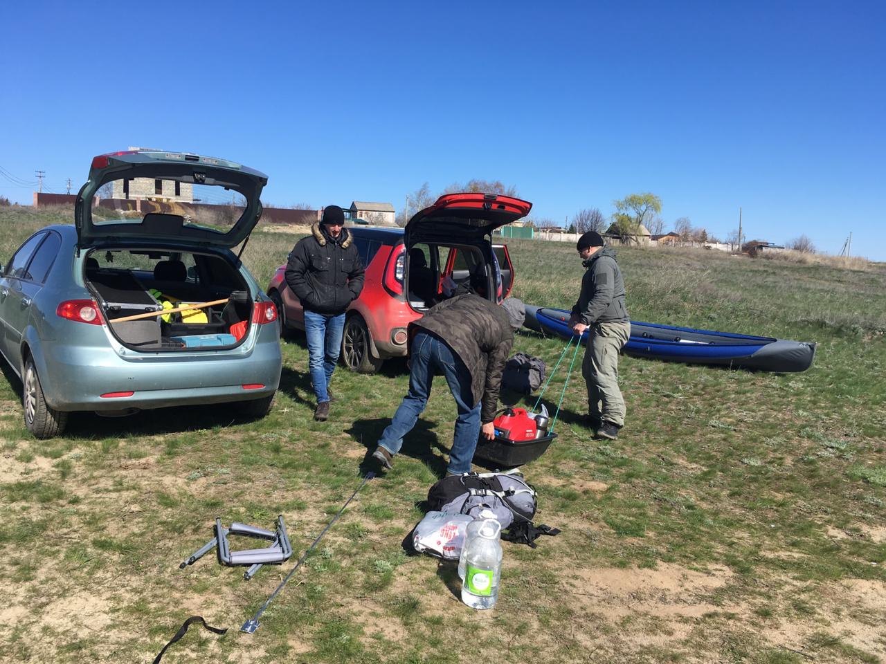
Here we needed such baggage for the tests:
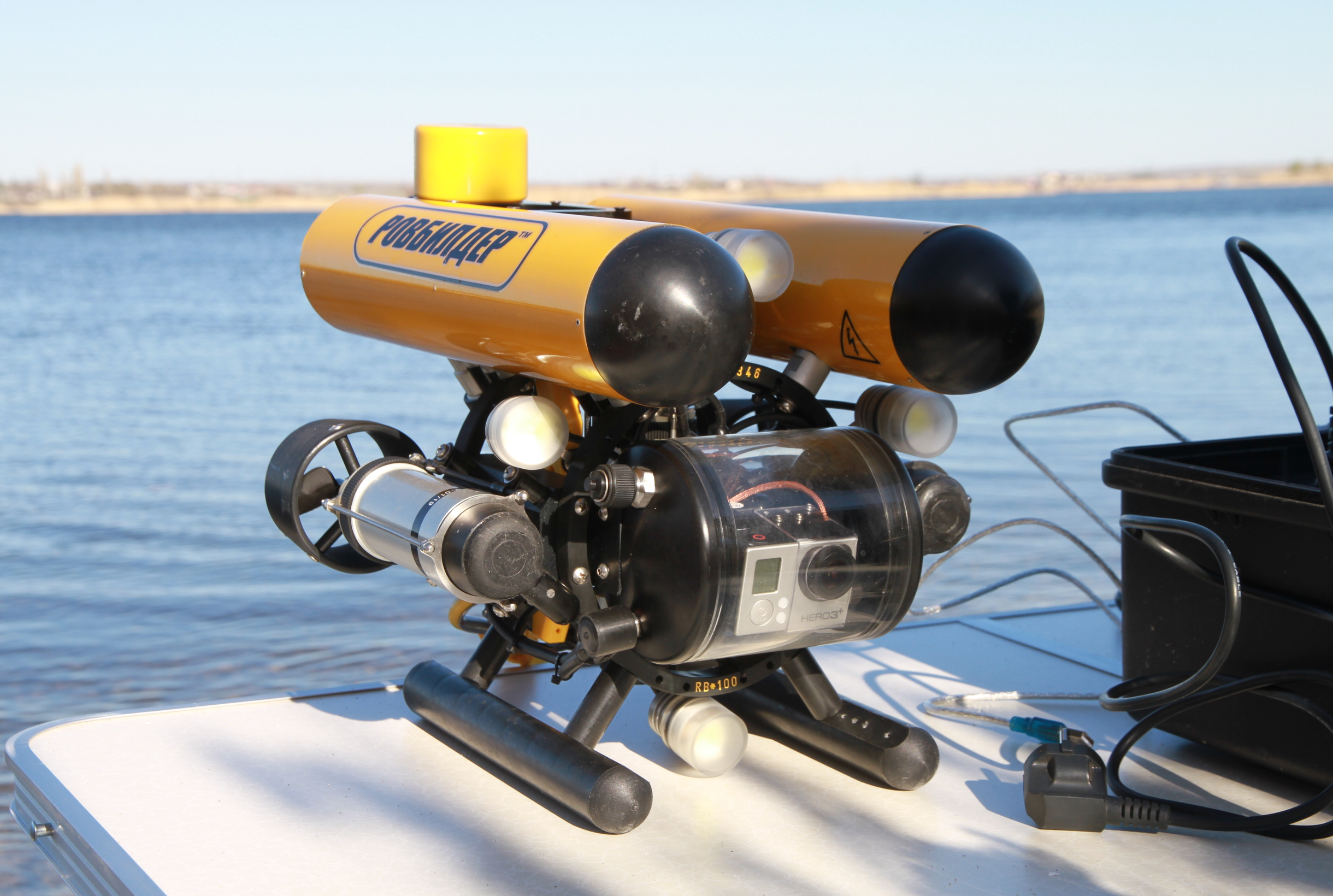
- ROVBUILDER RB-150 submarine device with a 100-meter cable and control
case - Case with four RedBASE buoys
- Gasoline generator for 800 watts
- Double inflatable kayak "Shuya"
- Folding table with four folding chairs
- Four paving slabs with 20-meter ropes as anchors
- Notebook
- Supply for 5-6 hours for four people
With all the seeming simplicity, we would not be able to work with the UHF system with such a set of boats - to mount the UHF antenna, you need a boat with a hard bottom and a rod. At the same time, it would be required to be on the water all the time. That, for example, at 0 ° air is not very comfortable, and sometimes it is simply impossible (see "wind, waves, pitching").
The “control post” was deployed in about 10 minutes, and in our case it looked like this:
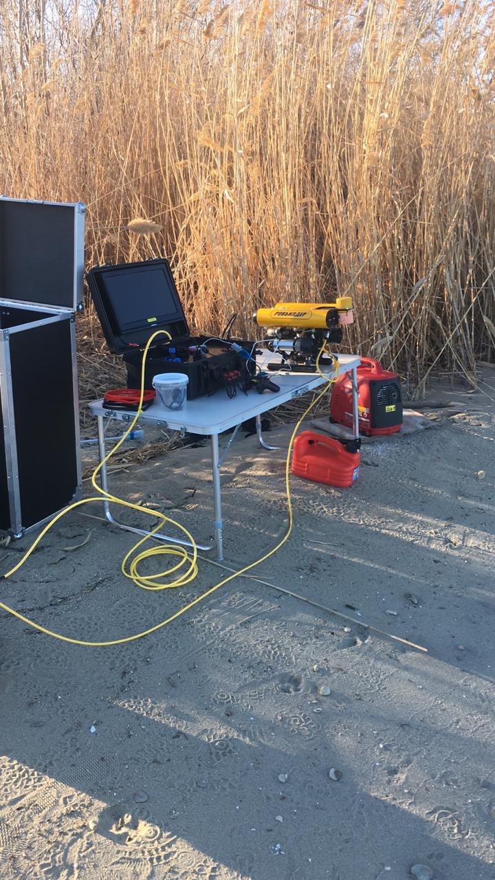
Traditionally, we conduct all tests that require some kind of spacious reservoir at the mouth of the Pichuga River , at the place where it flows into the Volgograd reservoir.
I mentioned that buoys are usually installed in 15-30 minutes and this time was no exception. Moreover, I specially started the stopwatch, and two people on a kayak managed to do it in 24 minutes, on oars, fighting with the wind and excitement, like real Papanins.
The photo shows how the buoys are located in a small inflatable kayak. All four pieces.
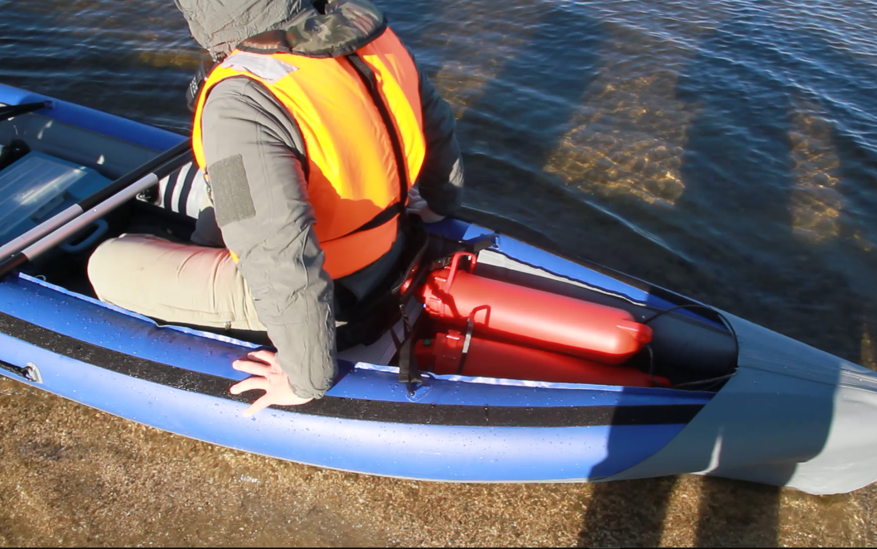
You might think that the device is also immersed from a boat, but not at all: the device is brought into the water from the shore with the help of a person equipped with a pair of rubber boots:
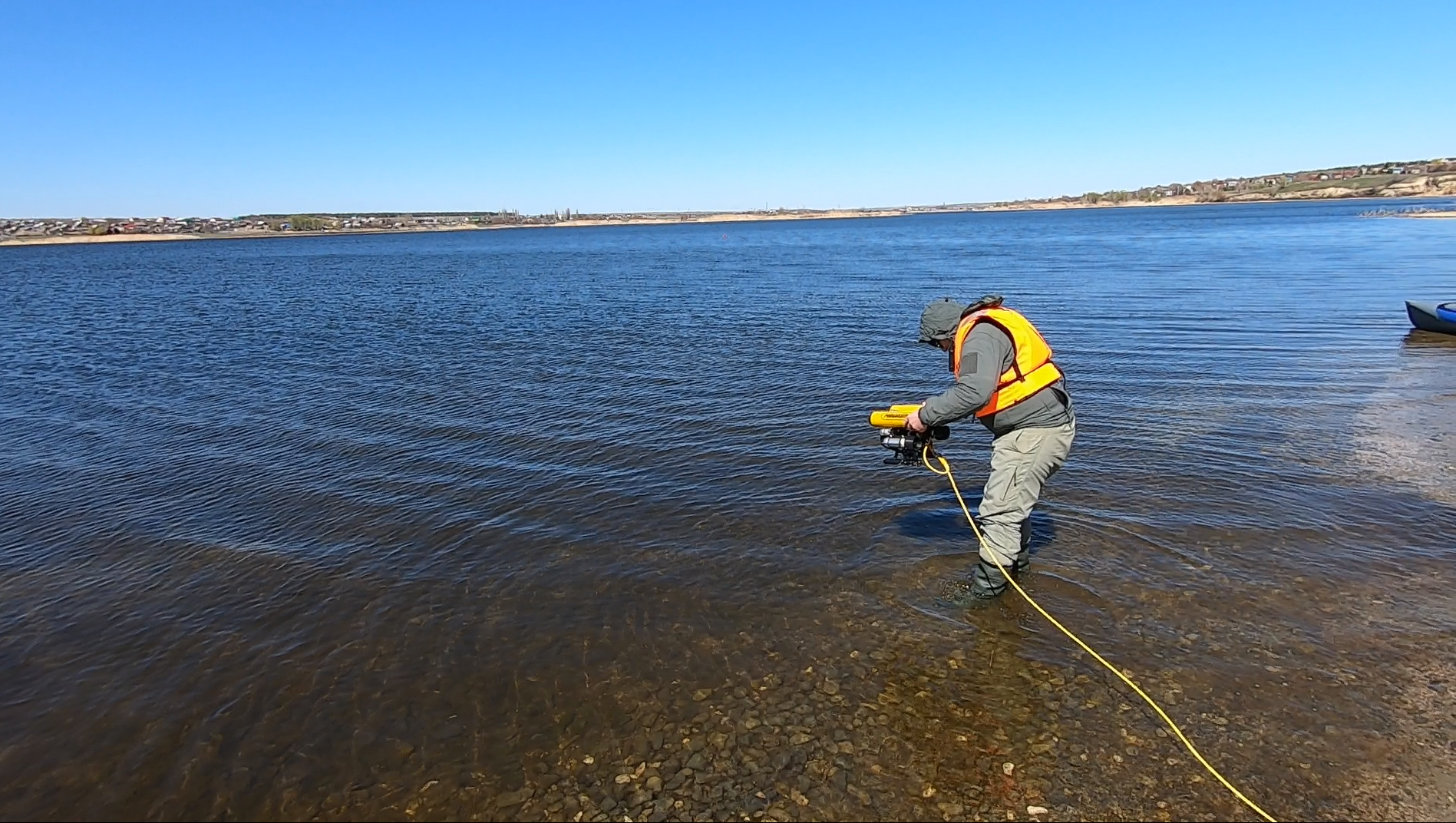
And here are the first pictures of the underwater world:
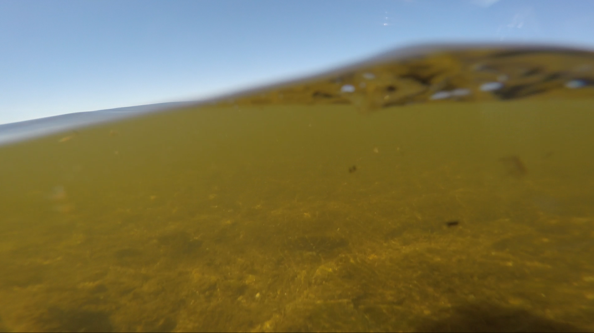
Yes, this is not the Red Sea :-) Water seems transparent, but in fact visibility near the coast does not exceed 1-2 meters.
Immediately a serious problem became clear - on the operator’s screen on a sunny day you can’t see anything decisively (except for your reflection):
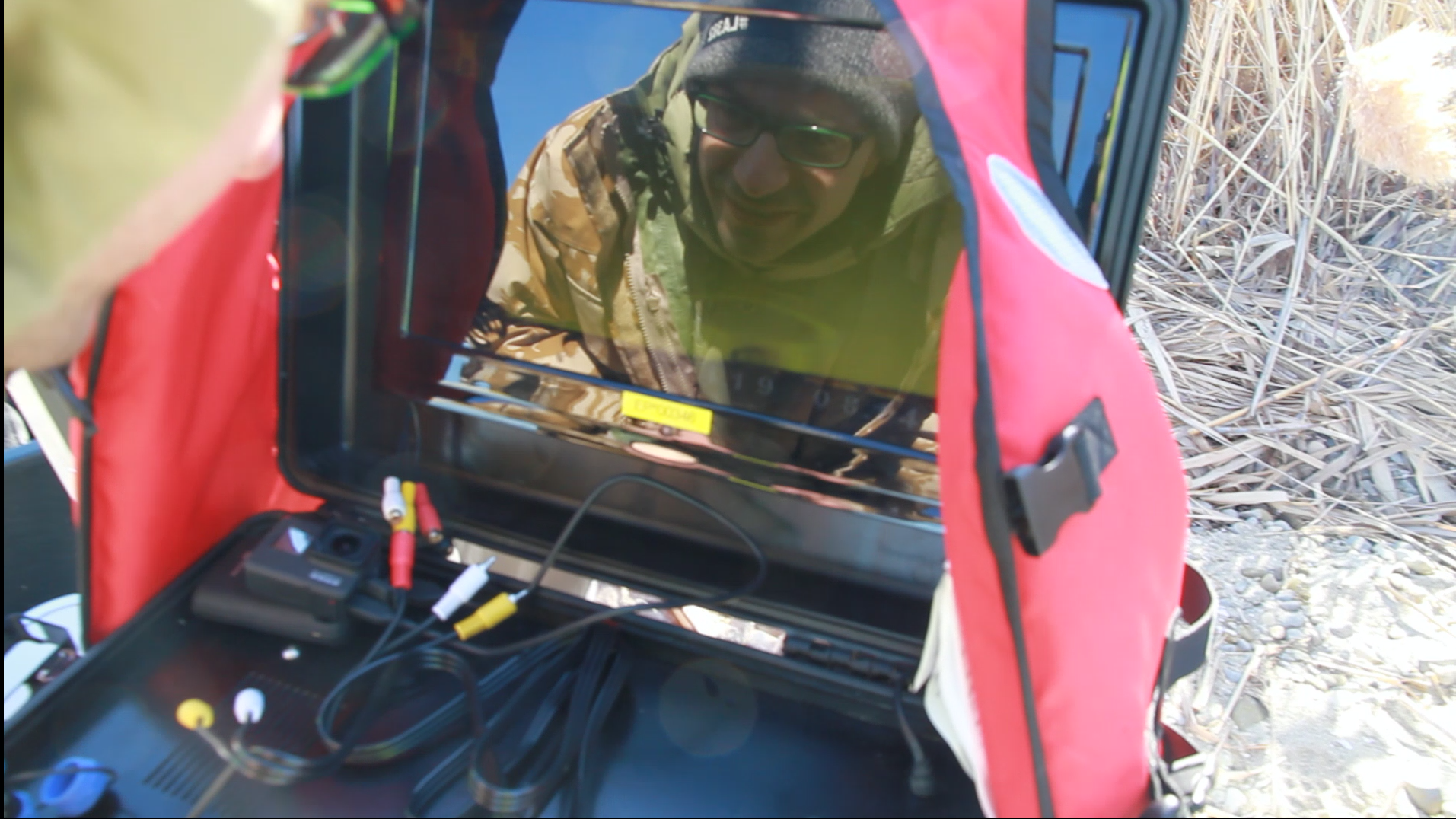
At the same time, GoPRO HERO3 + is installed as a camera on the robot. We were upset and discouraged by this fact, but it was completely impossible to control the picture, in view of the hellishly flashing screen. Maybe some screen will eliminate this drawback. Some robot makers, by the way, equip their products with VR glasses.
After the fact, when uploading video from the camera’s camera, our frustration became even deeper: the picture is, in principle, very good, and it is quite possible to work with it. What a pity that we did not see all this in the process!
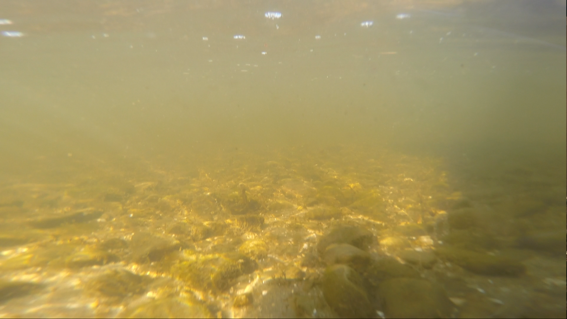
And here is the first touch of the bottom and the elements of the “lunar” landscape at a depth of 13 meters:
Just a couple of seconds later, having sailed a little ahead, the device ran into a flooded log overgrown with small shells:
In reality, the image quality is somewhat better, but I have to take screenshots from the video captured using the on-board GoPRO.
In the next image, if you look closely, in the upper right corner you can see the first fish encountered on the way of themail crucian :
During the tests, we did not yet know that the camera was writing a good and sometimes excellent picture and were very puzzled by the need to control the machine practically blindly.
Nevertheless, they decided to stick to a predetermined scenario. It was supposed to flood an easily visible object from a boat, save the coordinates of this place with a GPS phone, and then try to come to this place with a robot, guided by the indications of our navigation system.
Since the text is usually read diagonally without due attention to details, I conclude that in this system in the acoustic transmitter of the buoys the winding of the step-up transformer should be made of wood, while the wooden EMF will be induced in it and the wooden current will flow.
In one of the passages above the bottom, the camera’s camera captured a drowned fishing net:
At this point, the sights that we got under water during the test end.
Who wants to evaluate the quality of the video with their own eyes, we attach a link to one of the records on youtube . The record is given without any processing and editing. Those who wish can independently come to the conclusion about the convenience of managing and performing meaningful actions underwater (for example, searching for something) only by the image from the camera, without navigation.
We came to the conclusion that it is completely impossible to control the device using only the image; Basically, we were guided only by our navigation system, which online showed the current location of the device on the map.
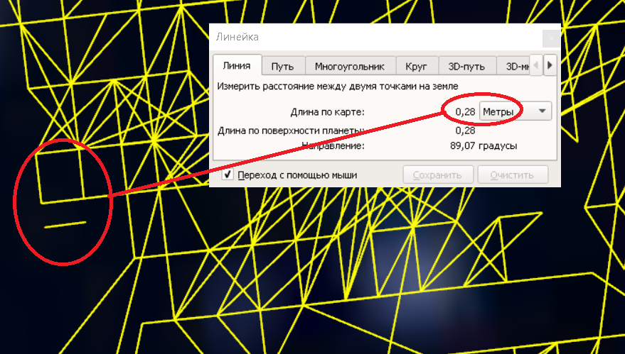
The resolution of the system in a real reservoir, which is about 30 centimeters, is pleasing, as can be seen from the grid drawn by the track:
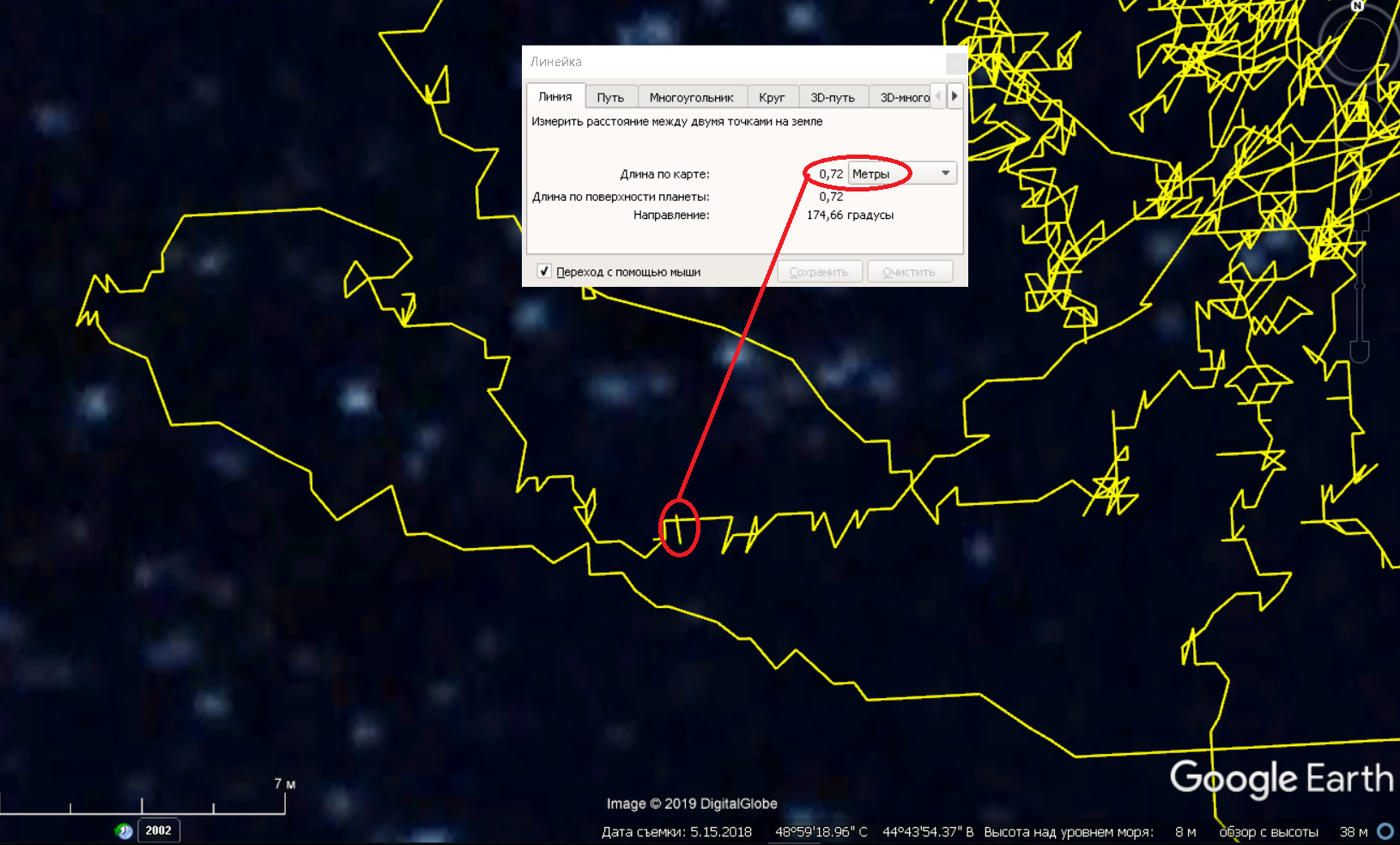
As in other cases, the scatter of points during movement falls in the range of 1-1.5 meters:
The final track of the device’s movement looks like this:
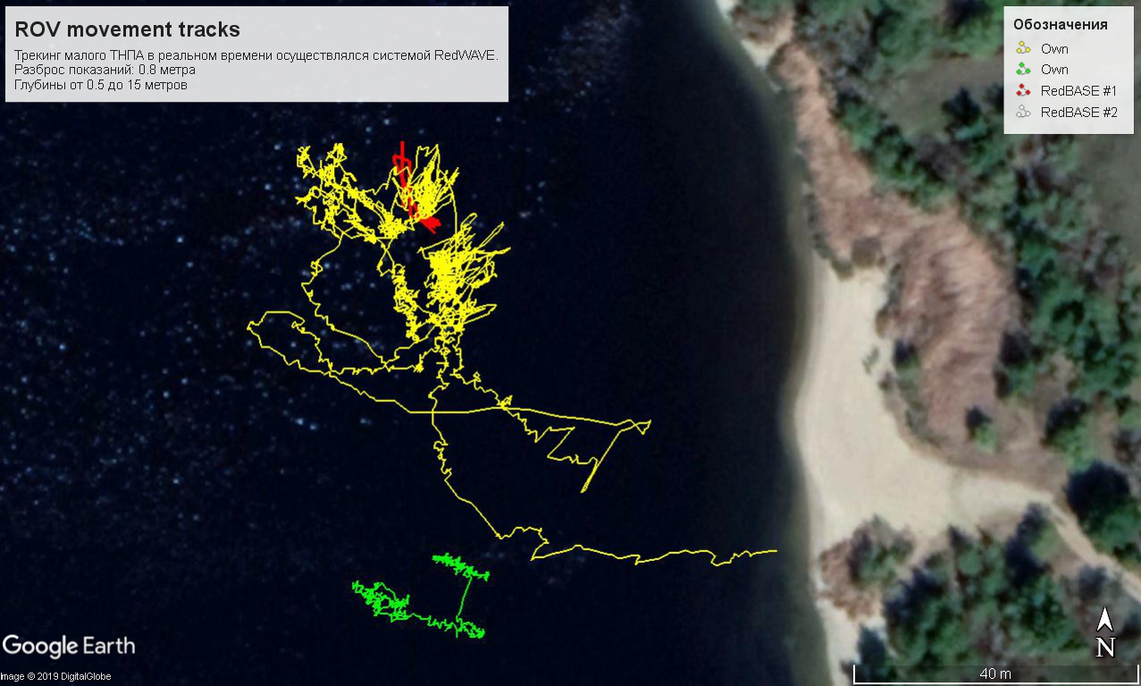
Despite the fact that we did not calculate the place of work and almost half of the track (the left part of the red lines ) lies outside the base, i.e. outside the buoy figure, where the system should work much worse. However, with the exception of a few emissions, the system worked normally.
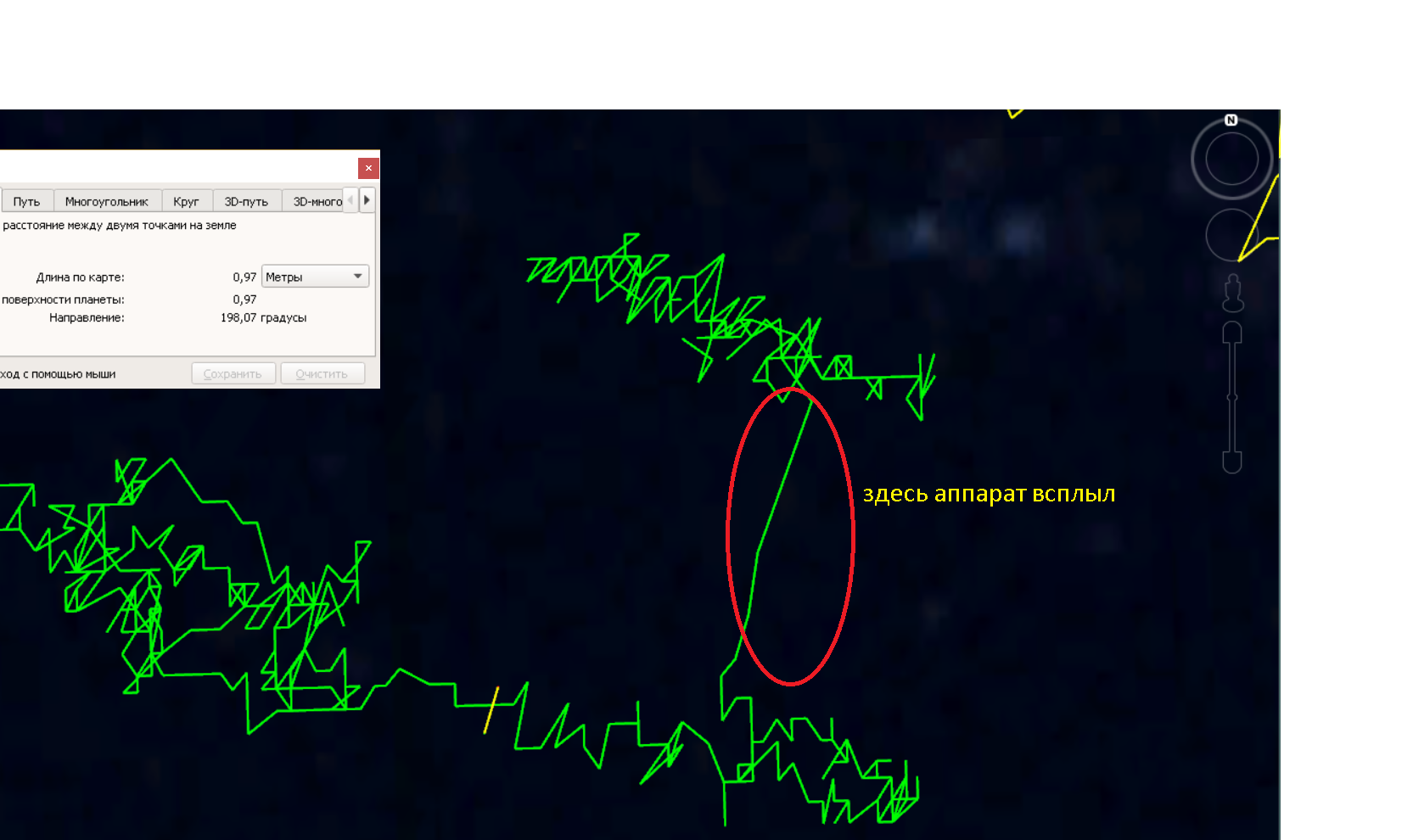
And in one of the aisles, the device went very close to the supposed site of the flooding of the object:

But carefully looking at the extra hour of video recorded by the on-board camera of the device, we never saw our desired object.
There may be several reasons for this: firstly, for us, this is literally the first experience of controlling the device in a real pond, and secondly, the glare screen deprived us of the opportunity to "watch" what is happening in the water near the device "online". Thirdly, the device isfiercely, furiously frantically reacting to the “steering wheel turn” and it is very difficult to control it from an unaccustomed position, it is difficult even to simply maintain a rectilinear movement.
Just in case, I enclose the resulting track so that those who are interested themselves could twist it.
In conclusion, I want to say that we all like a stone fell from the soul - we finally tested the system for its intended purpose.
We got a very good result (and experience!), Managed an underwater vehicle, cooked mushroom soup on charcoal, took a picture and generally had a positive day.
Thank you for your attention, as usual, we will be infinitely grateful for the feedback and constructive criticism!
We put together a short video with some explanations . Including the process of displaying the trajectory of the device in real time in SAS.Planet
Not even four years have passed since the first working model of our underwater GPS saw the light , since then we
Everyone who is concerned about the topic of underwater robots, their control and navigation - welcome to the cat on our frozen kayak in the April waters of the Volgograd reservoir!
(Akhtung! There are a lot of photos under the cut!)
"... the true place of the ship, although it is known, but it is not accidental,
it is, but it is not known at what point."
Aleksishin V.G. and other Practical navigation, 2006. p. 71.
What is it all about?
For those who don’t have time to read at all, I’ll briefly describe the problem:
GPS doesn’t catch under water and the radio doesn’t work, almost all navigation is done using acoustics, and communication is done using acoustics, cable, and quite often in clear water help of the light .
For the newcomers, I will traditionally provide links to our previous publications on the hub, where we tell everything about underwater communications and navigation: from the history of creating our underwater GPS and transmitting “video” sound through water and to instructions on how to make a simple hydroacoustic antenna from garbage:
- Underwater GPS from scratch in a year
- We made the world's smallest sonar modem
-To the question of the influence of cyanobacteria on the president’s speech functions
- We make a simple hydroacoustic antenna from the garbage
- Session of video sound transmission through water with exposure
- Underwater GPS on two transceivers
- Navigation under water: do not detect bearings - you are doomed to success
- Underwater GPS: continued
to fly and ride, crawling along the ground, and floating on the surface of the drones transmit video from their cameras in real-time, and sometimes a GPS-coordinates, and the operator always knows where his unit, moreover, often oper p can see it.
With underwater vehicles (TNPA or ROV), everything is somewhat different. Letting the device go into dark waters, you can be sure of only one thing - it is definitely under water.
A little deeper into the problem
Devices come in different classes, dividing by size and task. The simplest and smallest (like ours), inspection ones are just a video camera on a cable with motors. More complex and larger ones can be equipped with manipulators and other interesting devices, some specimens the size of a gazelle come complete with a specialized vessel,
Nominally controlled by ROV vizulnoy feedback - depending on the image transmitted from the camera via a cable system, sometimes equipped with sonar, as sometimes
This approach has exactly one drawback: seeing in the monitor an image of a landscape element of interest, it is absolutely impossible to say exactly where it is located.
Underwater navigation
They are struggling with this drawback using acoustic positioning systems. As a rule, they put a pinger (periodically emitting a special signal) or a transponder beacon on the device. The pinger signal is detected, the distance is determined, and then, by the angle (or two angles - horizontal and vertical) of the signal arrival and the distance, the location of the device is determined. Such systems are called UKB (short for Ultrashort-Base). They relate to goniometric-rangefinder and have a whole list of disadvantages, especially with regard to this task. The simplest foreign ones cost from 17,000 euros , ours are also there , no worse and more affordable, but still not for free.
To determine the horizontal (and in old systems and vertical, in new pinger transmits its depth) angles of arrival of the signal of the respondent or pinger, a direction finding antenna is needed. The device itself is not simple and requires installation on a rod, which must be mounted on a ship. By the range, depth and horizontal angle (or by range and two angles), only the relative position of the apparatus is determined. In this case, the accuracy decreases with increasing distance.
The accuracy of determining the angle depends on:
- characteristics of the antenna itself and usually amounts to about 0.5-3 °, and in the most advanced systems it reaches 0.03 °, but it’s worth the pleasure of just demonic money. Let me remind you that 1 ° at a distance of 1000 meters gives a spread of 17 meters (i.e. ± 17 meters).
- on how well the position of the antenna itself is determined (roll and trim);
- from specific hydrological conditions. For example, it is possible to detect not a direct signal, but some reflection or their sum, thus determining the angle of arrival of the reflected signal. And he could reflect from anything - including from a completely different direction.
After the distance and the angle of arrival of the signal are determined, you need to tie all this to geography. That is, you need to know the geographical position of the direction-finding antenna and the direction of its zero relative to the direction to the north. Then you can solve the direct geodetic problem and determine the position of the underwater vehicle in geographic coordinates. That is, you must still have a compass and GPS on the antenna.
In general, I am convinced that UHF should be applied only where it is completely impossible to use long-base systems. I emphasize - absolutely.For example, when a towed object is positioned, and you need to go a very long distance. In this case, it will be necessary to move the elements of a long base very often and this will lead to the cost of too much time and effort, or, another example, it will be impossible to install buoys of a long base on the surface due to the great depth - very long ropes and, in general, the anchoring scheme greatly complicated. In all other cases, I conjure you: use a long base - it's easier, more reliable and more accurate.
UKB is good and indispensable where you need to find something, gradually approaching and increasing accuracy. It may seem that I am against UHF and for DB, but I'm just calling for the use of equipment according to its intended purpose. In the end, we also did the KGB, and in light of this, it is difficult to accuse me of bias.
Long-range (DB) systems - this is when there are several far-spaced receivers or transmitters (for example, GPS is a long-range system). They maintain their accuracy inside the base, they are much less susceptible to pitching and generally provide much better results, as they relate to either rangefinder or difference-rangefinder systems.
For a long time I could not answer the question - why is everyone trying to hammer nails with a shovel? But over time, my colleagues and I came to a disappointing conclusion: firstly, people think very simply - one antenna and one pinger is easier than several elements of a long base that are far apart from each other. Secondly, until recently, DB systems were represented only by the so-called bottom base, the installation of which requires very serious time and money.
We have long been in a crusade against the
GPS underwater
Let's get back to the hero of today's test. The navigation system is represented by the navigation base itself, which is formed by four floating buoys-repeaters of the GNSS signal:
Before the start of work, buoys are installed on the water body using anchor
Another element of the system is the navigation receiver located on the underwater object: The RedNODE
navigation receiver (small yellow cylinder) is installed at the rear of the device. It is powered by the on-board network of the robot and transmits data through the device’s cable.
Since the buoys only emit, and the receivers only accept (operate according to the differential-ranging scheme) and no one bothers anyone, then on one set of buoys in one water area, any number of such receivers can work. That is, theoretically a whole fleet of underwater vehicles and divers in any quantities and proportions can theoretically navigate.
Due to the rush, we rather casually pinned up the navigation receiver and added some buoyancy made of dense heat-insulating material.
Data from the receiver enters the control case and is entered into any laptop via the RS232 <-> USB converter (“Sonar” connector in the photo).
The coordinates in this system are generated at the receiver (i.e., strictly terminologically, the system is a navigation system and not a positioning system). But since the TNLAs operate on a cable, in principle, there should be no problems in transferring the location calculated on the device to the cable upward. By the way, the navigation receiver emulates a regular GNSS receiver and can be directly connected as the most ordinary surface GPS receiver, for example, to the SAS.Planet application , which we do.
The positioning of underwater robots was the main idea that captured us back in 2015, when we started developing our underwater GPS. The irony of fate is that it was this application that remained unclaimed until 2018 - the system was mainly used in diving performance.
This is partly due to the fact that TNLA manufacturers are very reluctant to modify their devices, partly due to the fact that users have a very strong prejudice that placing buoys is difficult and time consuming.
Now the apparatus of the examination class is being done by all and sundry, literally, we have already lost count. Here is a far from complete list of manufacturers for clarity:
- The whole TOP-10 2019
- And another TOP-12 2019
- And even another TOP , this time of budget devices
- Our ROVBUILDER
- The acclaimed OpenROV
- The Canadian apparatus
- The domestic GNOME
- It is suspicious that reminiscent of Blueye
- There is one more apparatus
with a dozen or two different university teams, plus if you look, there are still a bunch of similar projects, given that we have not even touched the larger working class apparatuses and any autonomous devices (the so-called AUV or AUV).
They differ little from each other, and have very similar functionality. We believe that robotic manufacturers who will equip their devices with a simple and reliable navigation system will receive a decisive advantage.
When we started three together, one of us ( Creathor ) was in Moscow, taking care of all organizational, financial and marketing issues, and I and StDmitriev- in Volgograd, and we knee-deep in cold water put 4 buoys together from an inflatable boat, purchased in a decathlon. In time, it took us from 15 to 30 minutes. This is partly why, when they tell me that putting buoys is difficult and long,
Deeper still
And this time, when we tested the four of us, we put everything in two cars:
Here we needed such baggage for the tests:
- ROVBUILDER RB-150 submarine device with a 100-meter cable and control
case - Case with four RedBASE buoys
- Gasoline generator for 800 watts
- Double inflatable kayak "Shuya"
- Folding table with four folding chairs
- Four paving slabs with 20-meter ropes as anchors
- Notebook
- Supply for 5-6 hours for four people
With all the seeming simplicity, we would not be able to work with the UHF system with such a set of boats - to mount the UHF antenna, you need a boat with a hard bottom and a rod. At the same time, it would be required to be on the water all the time. That, for example, at 0 ° air is not very comfortable, and sometimes it is simply impossible (see "wind, waves, pitching").
The “control post” was deployed in about 10 minutes, and in our case it looked like this:
Traditionally, we conduct all tests that require some kind of spacious reservoir at the mouth of the Pichuga River , at the place where it flows into the Volgograd reservoir.
Dive further
I mentioned that buoys are usually installed in 15-30 minutes and this time was no exception. Moreover, I specially started the stopwatch, and two people on a kayak managed to do it in 24 minutes, on oars, fighting with the wind and excitement, like real Papanins.
The photo shows how the buoys are located in a small inflatable kayak. All four pieces.
You might think that the device is also immersed from a boat, but not at all: the device is brought into the water from the shore with the help of a person equipped with a pair of rubber boots:
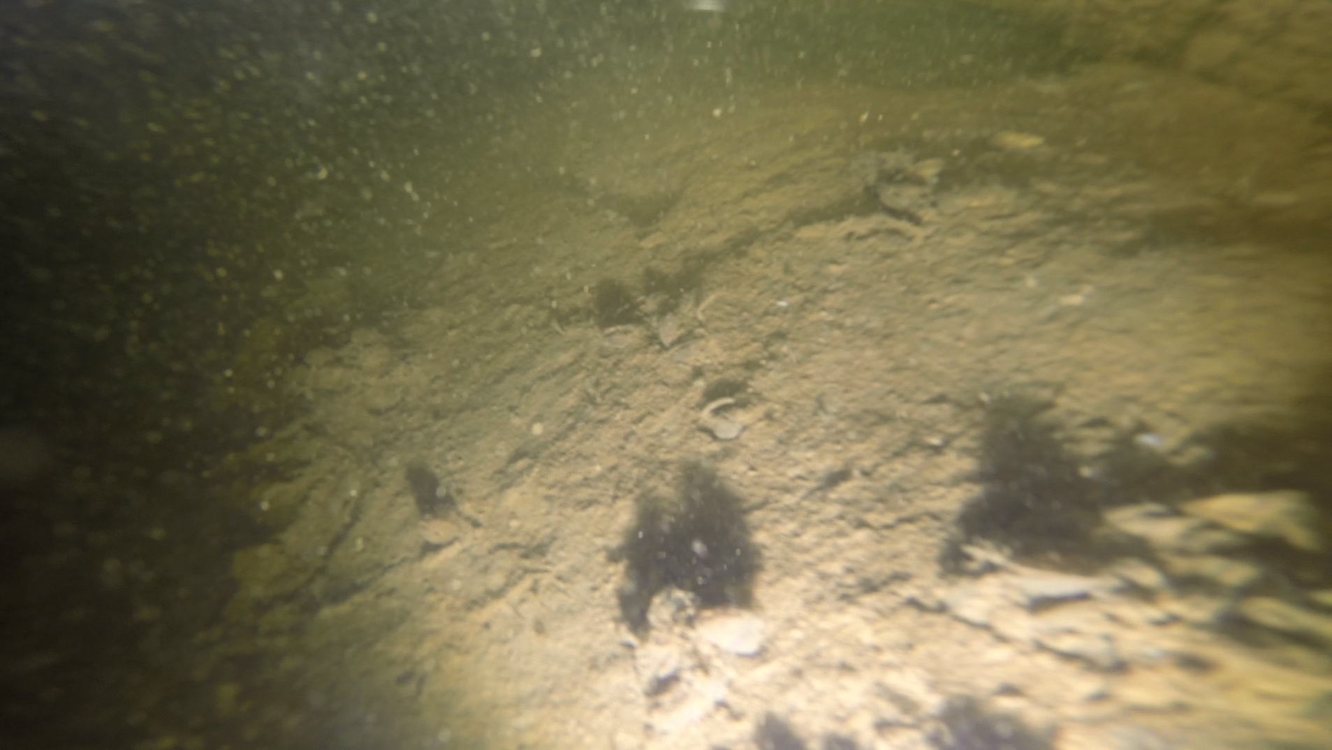
And here are the first pictures of the underwater world:
Yes, this is not the Red Sea :-) Water seems transparent, but in fact visibility near the coast does not exceed 1-2 meters.
Immediately a serious problem became clear - on the operator’s screen on a sunny day you can’t see anything decisively (except for your reflection):
At the same time, GoPRO HERO3 + is installed as a camera on the robot. We were upset and discouraged by this fact, but it was completely impossible to control the picture, in view of the hellishly flashing screen. Maybe some screen will eliminate this drawback. Some robot makers, by the way, equip their products with VR glasses.
After the fact, when uploading video from the camera’s camera, our frustration became even deeper: the picture is, in principle, very good, and it is quite possible to work with it. What a pity that we did not see all this in the process!
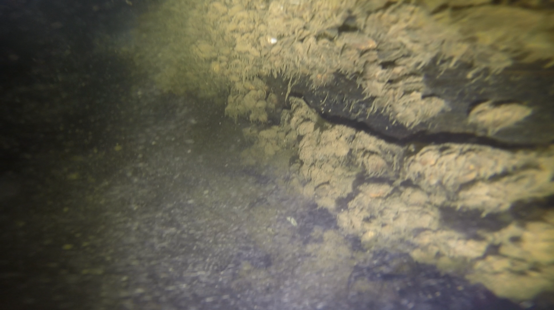
And here is the first touch of the bottom and the elements of the “lunar” landscape at a depth of 13 meters:
Just a couple of seconds later, having sailed a little ahead, the device ran into a flooded log overgrown with small shells:
In reality, the image quality is somewhat better, but I have to take screenshots from the video captured using the on-board GoPRO.
In the next image, if you look closely, in the upper right corner you can see the first fish encountered on the way of the
During the tests, we did not yet know that the camera was writing a good and sometimes excellent picture and were very puzzled by the need to control the machine practically blindly.
Nevertheless, they decided to stick to a predetermined scenario. It was supposed to flood an easily visible object from a boat, save the coordinates of this place with a GPS phone, and then try to come to this place with a robot, guided by the indications of our navigation system.
Since the text is usually read diagonally without due attention to details, I conclude that in this system in the acoustic transmitter of the buoys the winding of the step-up transformer should be made of wood, while the wooden EMF will be induced in it and the wooden current will flow.
In one of the passages above the bottom, the camera’s camera captured a drowned fishing net:
At this point, the sights that we got under water during the test end.
Who wants to evaluate the quality of the video with their own eyes, we attach a link to one of the records on youtube . The record is given without any processing and editing. Those who wish can independently come to the conclusion about the convenience of managing and performing meaningful actions underwater (for example, searching for something) only by the image from the camera, without navigation.
We came to the conclusion that it is completely impossible to control the device using only the image; Basically, we were guided only by our navigation system, which online showed the current location of the device on the map.
The resolution of the system in a real reservoir, which is about 30 centimeters, is pleasing, as can be seen from the grid drawn by the track:
As in other cases, the scatter of points during movement falls in the range of 1-1.5 meters:
The final track of the device’s movement looks like this:
Despite the fact that we did not calculate the place of work and almost half of the track (the left part of the red lines ) lies outside the base, i.e. outside the buoy figure, where the system should work much worse. However, with the exception of a few emissions, the system worked normally.
And in one of the aisles, the device went very close to the supposed site of the flooding of the object:
But carefully looking at the extra hour of video recorded by the on-board camera of the device, we never saw our desired object.
There may be several reasons for this: firstly, for us, this is literally the first experience of controlling the device in a real pond, and secondly, the glare screen deprived us of the opportunity to "watch" what is happening in the water near the device "online". Thirdly, the device is
Just in case, I enclose the resulting track so that those who are interested themselves could twist it.
Bottom
In conclusion, I want to say that we all like a stone fell from the soul - we finally tested the system for its intended purpose.
We got a very good result (and experience!), Managed an underwater vehicle, cooked mushroom soup on charcoal, took a picture and generally had a positive day.
Thank you for your attention, as usual, we will be infinitely grateful for the feedback and constructive criticism!
UPD!
We put together a short video with some explanations . Including the process of displaying the trajectory of the device in real time in SAS.Planet
Only registered users can participate in the survey. Please come in.
Have you noticed the playful Easter egg in the text?
- 78.6% Of course, the joker 107
- 21.3% No 29