Watches on ATtiny13
- Tutorial
I love the luminous clock, and when I needed another, I quickly assembled them on a breadboard of ATtiny85, the seven-segment indicator TM1637 and the real-time clock DS1307. However, during the assembly, the feeling that a simpler controller could be dispensed with did not leave me. And that turned out to be true.
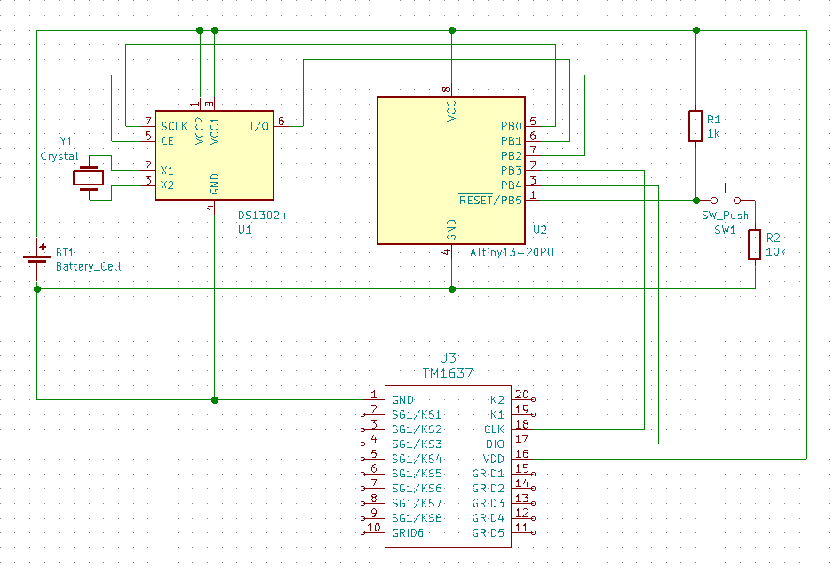
First of all, I studied the available solutions, and did not find any ready-made examples of connecting a two-wire DS1307 to ATtiny13. Because RTC has been replaced with a three-wire DS1302. Two more legs took the display connection. On the remaining half-foot of the Reset, there was a button for setting the time using StackOverflow and a pair of resistors.

The final connection of the elements Connection

diagram (from staticmain )
For good, you still need 4.7-10K resistors from the legs of the PB1 and PB2 microcontroller (upper center) to the power supply plus and a 0.1μF capacitor between the plus and minus, but it works without them.
The number of legs on the ATtiny13 is not the only problem. Available memory is also small - only 1Kb, as a result of which ready-made libraries are not suitable. The solution is to use the MicroCore package and the compact library for TM1637 . Nothing was found for the DS1302, so I had to create it myself on the basis of this repository. The resulting watch code is available on GitHub .
The TM1637 microcircuit, which controls a seven-segment indicator, has two-pin outputs, the status of which can be sent through the interface. However, they are not separated on the display module, and the library used does not support them.
It would be possible to breed a board for a larger indicator by placing microcircuits and a microcontroller on one printed circuit board, but it seemed to me that in this case it is easier to buy ready-made ones. Although, for me, this could make a good radio designer.
Disclaimer
The author does not have an engineering background and the work is not related to microcontrollers, because for sure everything is so-so. In addition, there is no optimization of energy consumption - we, the arduino, have not accepted it!
Hardware
First of all, I studied the available solutions, and did not find any ready-made examples of connecting a two-wire DS1307 to ATtiny13. Because RTC has been replaced with a three-wire DS1302. Two more legs took the display connection. On the remaining half-foot of the Reset, there was a button for setting the time using StackOverflow and a pair of resistors.

The final connection of the elements Connection

diagram (from staticmain )
For good, you still need 4.7-10K resistors from the legs of the PB1 and PB2 microcontroller (upper center) to the power supply plus and a 0.1μF capacitor between the plus and minus, but it works without them.
Software part
The number of legs on the ATtiny13 is not the only problem. Available memory is also small - only 1Kb, as a result of which ready-made libraries are not suitable. The solution is to use the MicroCore package and the compact library for TM1637 . Nothing was found for the DS1302, so I had to create it myself on the basis of this repository. The resulting watch code is available on GitHub .
Step-by-step instructions for those who want to repeat
- Parts ListIf you take on Ali-Express, then everything will take about 100 rubles.
- Microcontroller ATtiny13
- Display on TM1637
- Real Time Clock DS1302
- Quartz at 32768Hz
- Button
- A pair of resistors on 1K and 10K
- 3 volt battery holder
- Breadboard and jumpers or circuit board
- As a programmer - Arduino with the ArduinoISP sketch, supplied in the examples, uploaded to it. If you, like me, use Arduino Nano and pins 10-13 to connect, then you need to uncomment line 81
#define USE_OLD_STYLE_WIRING
After loading the sketch between the legs of the ground and dumping the Arduino, you need to put a capacitor at 10mF, although some are sewn without it.
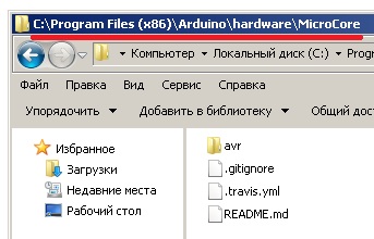
ATtiny13 firmware process through a slightly dusty Arduino - So that the Arduino IDE can work with ATtiny13, the contents of MicroCore are added to the% Program Files (x86)% / Arduino / hardware folder. After that, in the IDE, in the Tools section, the ATtiny13 board is selected with the settings: BOD disabled, LBO enabled, Clock 9.6 internal osc.


- Git sources already contain the necessary libraries for working with ds1302 and TM1637, which are configured to work on the pins (see the library header files), respectively the connection picture, so just download the repository and upload clock.ino to ATtiny13. The firmware will take up almost all the available space.

Assembled device on a breadboard. Green dots indicate the installation location of ATtiny for firmware (the orange plus power cable is very poorly visible). - Due to the peculiarity of connecting the button, inaccurate resistor ratings and supply voltage, it may be necessary to change the response threshold of analogRead in clock.ino (26th line).
- The plans were to manufacture the board using the LUT method, but the printer broke down in the process, so the verification of the resulting board was postponed indefinitely until it was fixed.
Instead of a conclusion
The TM1637 microcircuit, which controls a seven-segment indicator, has two-pin outputs, the status of which can be sent through the interface. However, they are not separated on the display module, and the library used does not support them.
It would be possible to breed a board for a larger indicator by placing microcircuits and a microcontroller on one printed circuit board, but it seemed to me that in this case it is easier to buy ready-made ones. Although, for me, this could make a good radio designer.
