Engine Mounted Gallet Switch for Minivac 601 Replica
- Transfer
- Tutorial
While working on a replica of the Minivac 601 — a training prototype of an electromechanical computer with 6-bit RAM — released in 1961 (just about today's holiday) —the author needed a wrench switch with the following characteristics:
- 1 direction, 16 positions
- lack of stopper
- opening of the previous pair of contacts to the closure of the next
- front mount
- rotation by hand or motor
That's the catch in the engine. Ready-made switches that are suitable for the rest of the parameters are either too tiny, or require large torque to change positions. I had to print my own on reed switches.
The author set up the 3D printer as follows:
Resolution - 0.2 mm
Filling - 20%
Filament - AMZ3D PLA
Without support The
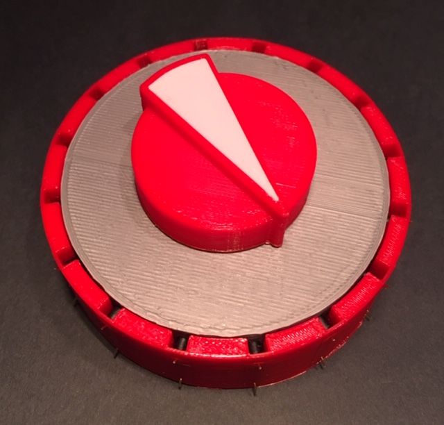
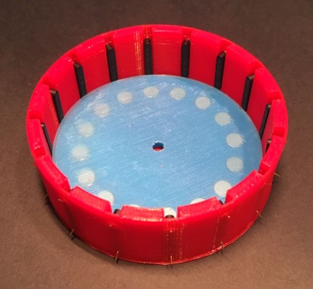
switch consists of a base , a handle , a magnet holder , gaskets for the rotor and the rotor itself (STL files are downloaded from the links). Of the finished parts, 16 reed switches and 18 disk magnets with a diameter of 6 mm and a thickness of 3 mm are required.

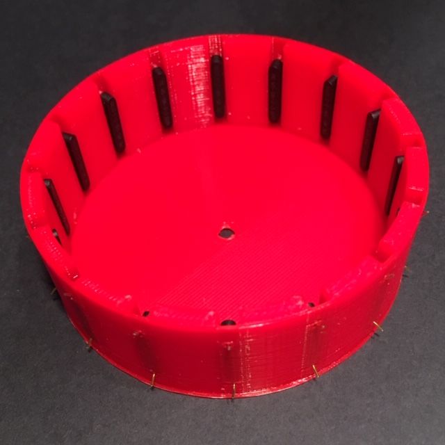
The assembly of the switch should begin with the installation of the reed switches in the base. The author at first tried to use reed switches without cases, but with cases it turned out to be more convenient.
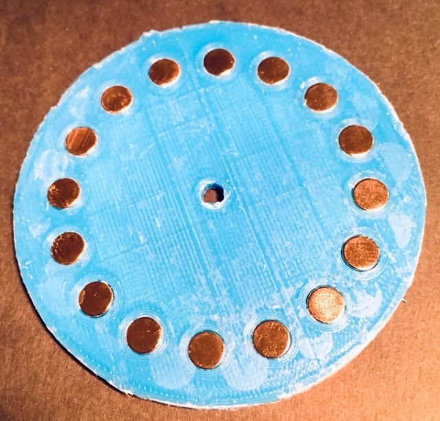
Then, glue 16 magnets flush with the surface, with the same poles up, into the magnet holder. These magnets are far from the reed switches and do not interact with them.
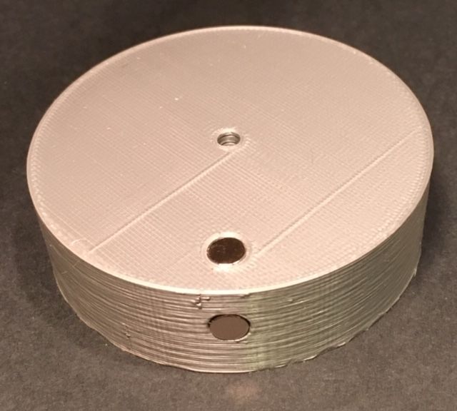
Glue the remaining two magnets into the rotor. The one at the bottom must be positioned so that it is attracted to the stationary magnets. So the switch will be fixed in any of 16 positions. And the one on the side will affect the selected reed switch.
Install the magnet holder in the base so that it fits into the groove, then the location of the magnets will exactly match the positions of the switch.

Put the gasket for the rotor on the magnet holder.
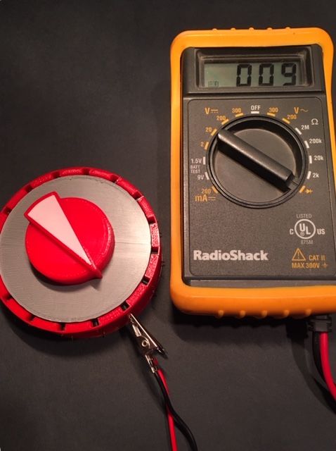
Temporarily stick the handle to the rotor with double-sided tape so that the “beak” points to the magnet on its side.

Put the rotor with the handle on the switch. Check whether it is well fixed in all positions.
Changing the switch position, ring all the reed switches.
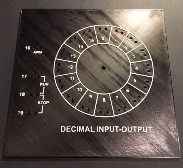
Peel off the handle. Install the switch on the back of the front panel of the Minivac 601 replica, and the handle on the front, connecting them with a pin through the hole in the panel, while again aligning the “beak” of the handle with the magnet on the side of the rotor. From the bottom of the base of the switch through the hole in it, press the motor shaft with gear into the switch rotor.
When using the replica, do not bring magnets to the switch, so as not to cause the closure of several reed switches at the same time.