How we overclocked CAD COMPASS-3D → Part 3
This is the final part of the article about accelerating KOMPAS-3D v18 ( Part 1 , Part 2 ). It is devoted to improvements in the calculation of mass-centering characteristics and what has been done to accelerate KOMPAS on the side of our geometric core C3D . And a little more about what kind of iron will allow you to feel the acceleration as much as possible.

There is another parameter that significantly affects the performance of KOMPAS - the calculation of mass-centering characteristics (MTC).
The calculation of the ICC is the "basic" for many functions, and it is simply necessary to accelerate it.
The difference in the calculation speed will be even more noticeable for the changed models (a large number of bodies and inserts require the calculation of the ICC) - they are marked with an asterisk *.
The following are the results of accelerating functions that depend on the calculation of the ICC:
Table 7. Executing the "Object Information" command for the root element of the tree, seconds (less is better).
Table 8. Entry time into the process of model properties, seconds (less is better).
Table 9. Create a report, seconds (less is better) (report on the first assembly level with default parameters).
Table 10. Execute the “Performance Management” command, seconds (less is better).
The developers of the geometric core C3D, which is the basis of KOMPAS-3D, also did not stand aside and made the necessary improvements to the kernel components to increase productivity.
C3D Modeler implements component-wise projection of a 3D model into a drawing. Previously, after editing (changing or moving) one of the components, all projections had to be recalculated again. The core task was to re-project only the specified modified components and those components that could be affected during the projection. This accelerated the construction of assembly projections with various modifications of its parts. Obviously, the smaller the number of assembly components affected by the changes, the greater and more noticeable is the effect in the speed of projection construction.
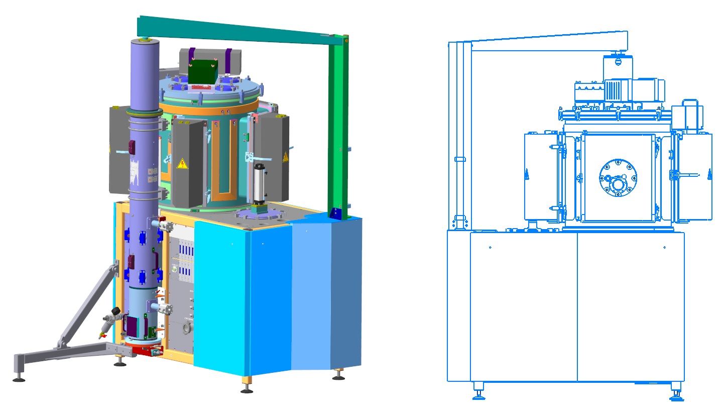
Component projection. 3D model of a vacuum-technological installation, developed by ESTO-Vacuum (Moscow)
Other C3D Modeler operations are also accelerated:
The C3D Solver parametric 2D solver accelerated by an average of 30-40%, and in some cases by several times due to the optimization of computational algorithms. For example, a situation in which when imposing restrictions on one object, the limitations of a large number of other objects are imposed. A striking example is the symmetry of a large number of different objects with respect to a straight line. Such cases accelerated 50-70 times. In the model, which served as the primary cause of the work, the calculation of the symmetry overlay was performed in 40 seconds. Now the operation is calculated no longer than 300 milliseconds.

Symmetry of a large number of objects relative to a linear object
A fivefold increase in the performance of C3D Solver was achieved when working with interpolation splines that pass through a set of preset points. The larger the spline (the number of points that specify it), the greater the acceleration. For a spline passing through 100-200 points, tenfold acceleration is recorded.
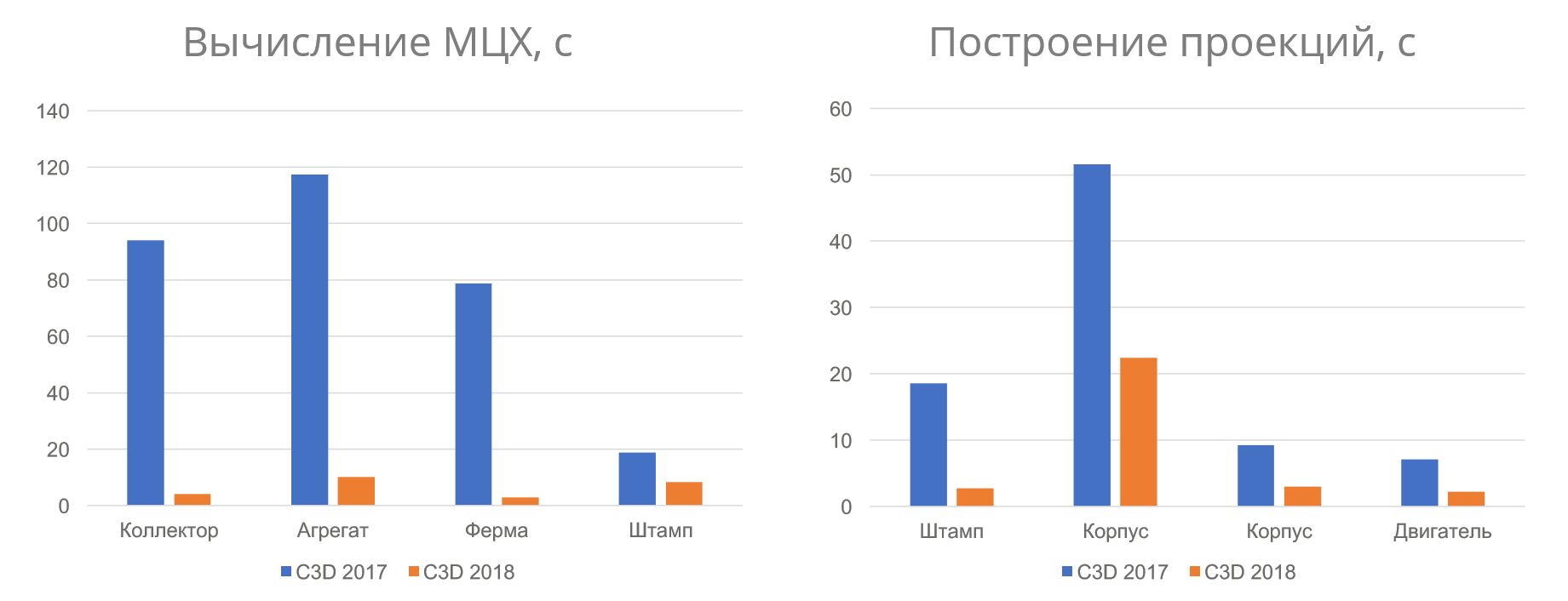
Speed of operations before and after optimization of the geometric core of C3D
There were some improvements in the parameters used for triangulation. The fact that we began to use the angular deviation, we have already mentioned in the part devoted to rendering . A number of optimizations were performed to calculate triangulation using angular deviation and to more optimally break down some types of surfaces.
The functionality of the new version allows you to use the capabilities of powerful graphics cards at full capacity. The resources of multi-core processors will be more fully involved.
The user will benefit from multi-core processors in the following scenarios:
We recommend using multi-core processors not just like that, but because the indicated functions are frequency ones.
The recommended configuration for comfortable work with conventional assemblies is shown in table 11, and for large assemblies - in table 12.
Table 11. Configuration for comfortable work.
Table 12. Configuration for working with large assemblies.
You need to strive to build balanced systems, especially if you work with large assemblies. But you always need to focus on a specific 3D assembly. You can’t definitely say “this assembly is large”, you cannot focus only on the number of components. After all, there is also the complexity of execution.
Already there are some reserves to speed up rendering.
In the "draft" projection, the possibility of increasing the accuracy of the method is being worked out.
In addition to algorithmic optimization, we will continue to optimize the processes of user interaction with the system in order to reduce the number of actions in monotonous operations.
A performance monitoring system will also be developed to constantly monitor the speed of KOMPAS-3D. The plans include the expansion of controlled scenarios and the base of models used in the tests.
The service pack finalized several areas regarding speed. Finer shader optimization, more efficient implementation of clipping invisible objects. Improved performance when working with dynamic section.
And also there was realistic transparency with a new level of performance:
Starting with speeding up rendering, work on v18 went too far. Now we sometimes joke that, and further working on accelerations, we will reach negative values in this way. But in fact, is this a joke, can only be understood with time. In the meantime, we offer to read more about the performance of KOMPAS-3D. Here you can learn how to quickly work with assemblies of any complexity. And may the co-creator tool be with you.
About the calculation of the ICC
There is another parameter that significantly affects the performance of KOMPAS - the calculation of mass-centering characteristics (MTC).
The calculation of the ICC is the "basic" for many functions, and it is simply necessary to accelerate it.
Read more about the ICC.
Mass-centering characteristics (MCC) are the physical data of the product: mass, area, volume, coordinates of the center of mass , planar, axial and centrifugal moments of inertia .
The MLC can be obtained by calculation or set manually, they can be calculated for the 3D model and for the drawing.
The calculated data is used to display the mass in the properties of the model, in reports, in the stamp of an associative drawing, etc.
Below are examples of MTC calculation times.Konstantin Gulevsky, programmer:
“It would seem that calculating the volume and mass of a body is not such a difficult task. Indeed, such calculations are performed in microseconds; moreover, the C3D geometric core successfully performs such calculations in different threads. However, when it comes to "large assemblies", the calculation of the ICC may drag on for minutes, and in some cases for tens of minutes. The reason for this is primarily the complex relationships of components: a change in the characteristics of one component affects the characteristics of many others. To speed up the calculation, a special graph was developed that determined the relationships between components and bodies. The calculation of the ICC became possible to carry out in stages:
- The MLC of all bodies is calculated (the bodies do not affect each other, i.e., a change in the MLC of one body cannot lead to a change in the MLC of another body).
- The MLCs of components independent of each other are calculated, i.e., those for which a change in the MLC of one component does not lead to a change in another.
Step 2 is performed recursively until the ICC of all the inserts is calculated.- The MTC of the head assembly is calculated.
This algorithm significantly accelerated the calculation of the ICC, primarily due to the elimination of repeated calculations for the same components. But also thanks to this approach, it became possible to parallelize the calculation of the ICC at the component level. When performing steps 1 and 2, the calculation of the ICC of bodies and assemblies is performed in different streams. Such optimizations also gave a performance boost.

The difference in the calculation speed will be even more noticeable for the changed models (a large number of bodies and inserts require the calculation of the ICC) - they are marked with an asterisk *.
Hereinafter, measurements were taken on a PC with the following configuration:Table 6. ICC calculation time, seconds (less is better). Modified models are marked with an asterisk *.
CPU: Intel Core i7-6700K 4.00 GHz
RAM: 32 Gb
GPU: NVidia Quadro P2000
OS: Microsoft Windows 10 x64 Professional
| Model | The “МЦХ model” command, time of calculation of МЦХ, sec | ||
| V16.1 | v17.1 | v18 | |
 Vacuum technological installation | 1,5 | 1,5 | 0.6 |
| * Vacuum technological installation (after change) | 17.9 | 10.8 | 2.2 |
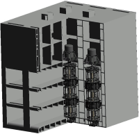
 Multipurpose Unified Box Body | 37,4 | 60.3 | 1.8 |
 Northern Tidal Power Station | 316.0 | 104.4 | 4.6 |
 Marine power plant gearbox | 359.6 | 8.9 | 1,0 |
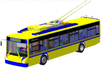 Trolley bus | 3.3 | 4,5 | 0.7 |
| * Trolleybus (after change) | 21,2 | 22.6 | 2,5 |
Evgeny Filimonov, tester:
“The calculation of the ICC is used for many functions of COMPAS-3D:
- saving the model, especially after making changes,
- output of relevant information about the mass of the model, individual components of the assembly
- reporting
- calculation of data in the mass column for the "Performance Management" window,
- when creating associative drawings to obtain the mass value of the assembly.
These are the main, but by no means all cases where ICC calculation is needed.

The following are the results of accelerating functions that depend on the calculation of the ICC:
Table 7. Executing the "Object Information" command for the root element of the tree, seconds (less is better).
| Model | Team "Information about the object", with | ||
| V16.1 | v17.1 | v18 | |
Northern Tidal Power Station | 101.5 | 109,2 | 10.7 |
Marine power plant gearbox | 50.9 | 14.1 | 1.7 |
Multipurpose Unified Box Body | 12,4 | 10.9 | 1.7 |
Trolley bus | 2.9 | 6.4 | 0.3 |
Table 8. Entry time into the process of model properties, seconds (less is better).
| Model | Entrance to the process of model properties, with | ||
| V16.1 | v17.1 | v18 | |
Northern Tidal Power Station | 295.2 | 108.1 | 1,0 |
Marine power plant gearbox | 267.1 | 13.5 | 2.7 |
Multipurpose Unified Box Body | 35,4 | 21.0 | 2.1 |
Trolley bus | 3,1 | 10.0 | 0.7 |
Table 9. Create a report, seconds (less is better) (report on the first assembly level with default parameters).
| Model | Create report command for assembly, with | ||
| V16.1 | v17.1 | v18 | |
Northern Tidal Power Station | 305.8 | 105.5 | 12.1 |
Marine power plant gearbox | 122,4 | 7.4 | 6.8 |
Multipurpose Unified Box Body | 32,2 | 10.3 | 2.1 |
Trolley bus | 10.0 | 6.1 | 1,5 |
Table 10. Execute the “Performance Management” command, seconds (less is better).
| Model | Team "Performance Management", with | ||
| V16.1 | v17.1 | v18 | |
Northern Tidal Power Station | 66,4 | 107.8 | 9.9 |
Marine power plant gearbox | 262.8 | 12,4 | 1.3 |
Multipurpose Unified Box Body | 34.0 | 10.8 | 1,5 |
Trolley bus | 2,8 | 5.5 | 0.1 |
How the geometric core accelerated KOMPAS-3D v18
The developers of the geometric core C3D, which is the basis of KOMPAS-3D, also did not stand aside and made the necessary improvements to the kernel components to increase productivity.
C3D Modeler implements component-wise projection of a 3D model into a drawing. Previously, after editing (changing or moving) one of the components, all projections had to be recalculated again. The core task was to re-project only the specified modified components and those components that could be affected during the projection. This accelerated the construction of assembly projections with various modifications of its parts. Obviously, the smaller the number of assembly components affected by the changes, the greater and more noticeable is the effect in the speed of projection construction.
Component projection. 3D model of a vacuum-technological installation, developed by ESTO-Vacuum (Moscow)
Other C3D Modeler operations are also accelerated:
- projection of thread symbols,
- deleting and overlapping segments when projecting,
- special cases of calculating the result of a Boolean operation for a large number of edges and cycles on the faces of models,
- work with custom attributes.
The C3D Solver parametric 2D solver accelerated by an average of 30-40%, and in some cases by several times due to the optimization of computational algorithms. For example, a situation in which when imposing restrictions on one object, the limitations of a large number of other objects are imposed. A striking example is the symmetry of a large number of different objects with respect to a straight line. Such cases accelerated 50-70 times. In the model, which served as the primary cause of the work, the calculation of the symmetry overlay was performed in 40 seconds. Now the operation is calculated no longer than 300 milliseconds.
Symmetry of a large number of objects relative to a linear object
A fivefold increase in the performance of C3D Solver was achieved when working with interpolation splines that pass through a set of preset points. The larger the spline (the number of points that specify it), the greater the acceleration. For a spline passing through 100-200 points, tenfold acceleration is recorded.
Speed of operations before and after optimization of the geometric core of C3D
There were some improvements in the parameters used for triangulation. The fact that we began to use the angular deviation, we have already mentioned in the part devoted to rendering . A number of optimizations were performed to calculate triangulation using angular deviation and to more optimally break down some types of surfaces.
Iron for v18
The functionality of the new version allows you to use the capabilities of powerful graphics cards at full capacity. The resources of multi-core processors will be more fully involved.
The user will benefit from multi-core processors in the following scenarios:
- when creating projection views (associative drawings),
- when calculating the ICC and performing the processes tied to it,
- multi-core will allow you to open files even faster, since multi-threaded calculation of levels of detail will work,
- upon import
- in operations that create a large number of geometric objects (bodies).
We recommend using multi-core processors not just like that, but because the indicated functions are frequency ones.
The recommended configuration for comfortable work with conventional assemblies is shown in table 11, and for large assemblies - in table 12.
Table 11. Configuration for comfortable work.
| CPU | Multi-core processor (4 cores) with a clock frequency of 3GHz and higher |
| Video card | Modern, discrete, preferable to the production of NVIDIA: with support for OpenGL 4.5, the amount of video memory 2 GB or more |
| RAM | 8 GB or more |
Table 12. Configuration for working with large assemblies.
| CPU | Multi-core processor (4 cores or more) with a clock frequency of 4GHz and higher |
| Video card | Современная, дискретная, производства NVIDIA: с поддержкой OpenGL 4.5, объемом видеопамяти 4 ГБ и более, пропускная способность видеопамяти (Memory Bandwidth ) — 140 ГБ/с и более *параметры видеокарт можно посмотреть на сайте производителя видеочипа |
| Оперативная память | DDR4, 16 ГБ и более (лучше 32 ГБ) На объем ОЗУ нужно обратить больше внимания. При ее недостатке система может начать использовать файл подкачки — этот файл размещается на диске, и работа с ним значительно (!) медленнее, чем с оперативной памятью |
| Дисковая система | SSD-диск в качестве места установки КОМПАС-3D и хранилища КОМПАС-документов |
You need to strive to build balanced systems, especially if you work with large assemblies. But you always need to focus on a specific 3D assembly. You can’t definitely say “this assembly is large”, you cannot focus only on the number of components. After all, there is also the complexity of execution.
As part of work on version v18, we collaborated with developers from NVIDIA.
Since the volume of changes on the rendering side was large, it was necessary to update the special profile that is used for KOMPAS-3D in professional Quadro cards. An updated profile has appeared in drivers since version v391.89.
In the new version of the driver, it was also possible to eliminate the delays before zooming in on some models.
What's up?
Already there are some reserves to speed up rendering.
The plans accelerate the drawing of specific types of objects - this is a variety of annotations, carvings.Александр Тулуп, программист:
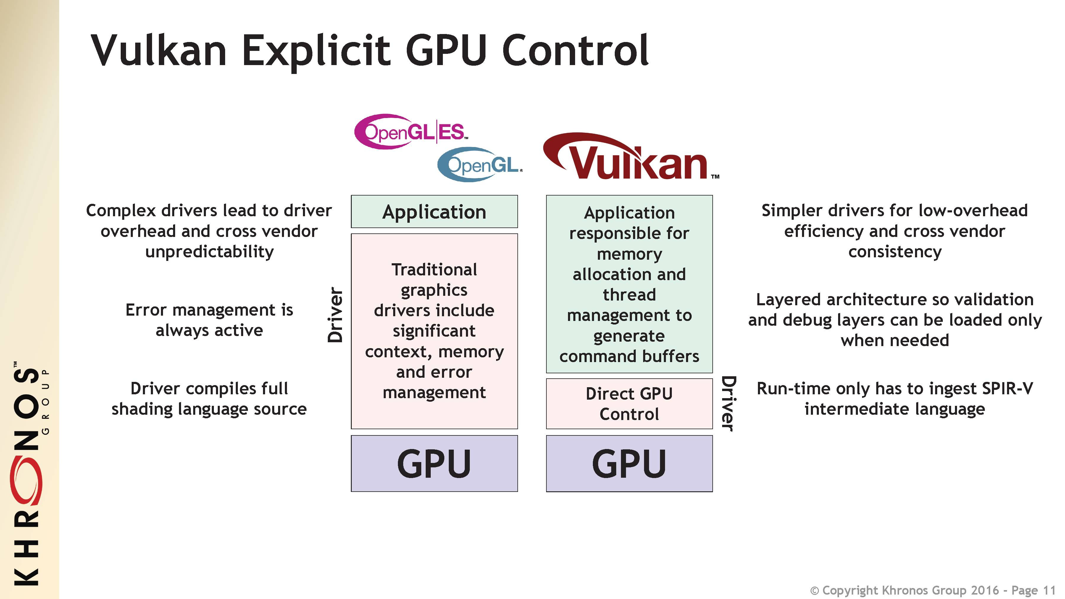
«В перспективе можно постепенно переходить на VulkanAPI. В данном случае драйвер уже не пытается выполнить за разработчика его работу, как это было в случае с OpenGL. Необходимо самостоятельно следить за корректностью входных данных. Но при этом стоимость отрисовочного вызова значительно ниже, а если учесть изначальную поддержку многопоточности, то можно достичь большей производительности меньшими усилиями.
VulkanAPI
OpenGL разрабатывался во времена, когда многопоточность не была так широко распространена. Из него уже выжали все, что могли, и в последнем обновлении добавили возможности для более плавного перехода на VulkanAPI.

In the "draft" projection, the possibility of increasing the accuracy of the method is being worked out.
In addition to algorithmic optimization, we will continue to optimize the processes of user interaction with the system in order to reduce the number of actions in monotonous operations.
A performance monitoring system will also be developed to constantly monitor the speed of KOMPAS-3D. The plans include the expansion of controlled scenarios and the base of models used in the tests.
And we have already released KOMPAS-3D v18.1!
The service pack finalized several areas regarding speed. Finer shader optimization, more efficient implementation of clipping invisible objects. Improved performance when working with dynamic section.
And also there was realistic transparency with a new level of performance:
Starting with speeding up rendering, work on v18 went too far. Now we sometimes joke that, and further working on accelerations, we will reach negative values in this way. But in fact, is this a joke, can only be understood with time. In the meantime, we offer to read more about the performance of KOMPAS-3D. Here you can learn how to quickly work with assemblies of any complexity. And may the co-creator tool be with you.