How to promote a newbie and not break anything
Searching, interviewing, testing, selecting, hiring, adapting is a difficult and understandable way for each of us - both the employer and the employee.
A beginner does not have the necessary specialized competencies. Even an experienced specialist has to restructure. The manager is pressured by questions, what tasks should be set for a new employee at the start and what time should be devoted to them? At the same time, ensuring interest, involvement, drive and integration. But do not risk critical business tasks.
For this, we are launching relay internal projects. They consist of independent short stages. The results of such work serve as the foundation for subsequent developments and allow the newcomer to show himself, join the team with an interesting task and without risk filling up an important project. Here is the accumulation of experience, and acquaintance with colleagues, and the opportunity to show oneself from the best side, when there are no strict restrictions on the part of legacy.
An example of such a relay development was the theme of a rotational screen based on a stroboscopic effect with the possibility of displaying an arbitrary user dynamic image made on the phone screen onto it . Prototypes can be found here .
The work was carried out sequentially by several employees and will be continued by new ones during their onboarding (from two weeks to a month depending on the abilities and level of competencies) ..
The steps were as follows:
a) to think over the design (having studied the available samples, description of analogues, showing creative initiative);
b) develop a circuit diagram, dissolve it on the board;
c) develop a protocol for transferring the image from the phone to the device;
d) provide control from a smartphone via Bluetooth LE.
The starting option was to use something very compact, such as a three-leaf spinner, which, when manually rotated, began to show inscriptions. The BLE module was located in one lobe, ten RGB-LEDs in the second, an optical sensor in the third, and a battery in the center. A circuit diagram was drawn up and the first experiments were conducted. It became clear that the picture quality level is very low, the resolution is small, the game effect is short-lived, the possibilities are modest. Yes, and spinners are gone as quickly as they appeared. It was decided to raise the bar and develop a rotary stroboscopic screen. At least it can be used for practical purposes at exhibitions and conferences and in the near future interest in such solutions will not disappear.
Regarding the design, there were two main questions: how to arrange the LEDs (in a vertical plane, as in the example above or in horizontal) and how to power a rotating board with LEDs.
For educational purposes, the LEDs were located only in a horizontal plane. As for the board's power supply, there was an important choice: either we take the collector motor bulky, noisy, but cheap, or we use a more elegant solution with non-contact power transmission using two coils - one on the engine and the other on the board. The solution, of course, is elegant, but more expensive and longer, because coils had to be calculated first, and then wound (preferably not on the knee).
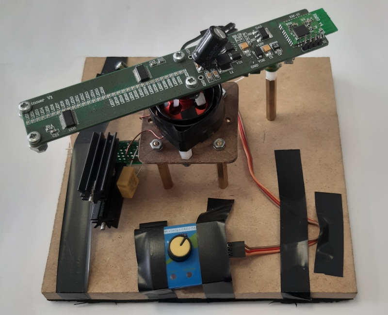
It looks like the resulting prototype
The specifics of mass production is such that every extra cent in cost is of importance. Success can be determined by the cost of a handful of passivation. Therefore, it is often necessary to choose a less effective, but cheaper option, so that the manufacturer can maintain commercial competitiveness. Therefore, imagining that the rotation screen will be launched into mass production, the developer chose a commutator motor.
The resulting prototype sparkly sparkled at the start, made noise and shook the table. The design that ensured stability turned out to be so heavy and dimensional that it did not make sense to bring it to a serial prototype. Rejoicing for the intermediate success, they decided to replace the engine with a rotating transformer with an air gap. Another reason was the inability to power the engine from the computer's USB port.
The basis of the LED board was our RM10 module and six MBI5030 LED drivers .
Drivers have 16 channels with the ability to independently control each. Thus, 6 such drivers and 32 RGB LEDs in total have the ability to show 16 million colors.
To synchronize and stabilize the output image, two MRSS23E magnetoresistive Hall sensors were used .
The plan was simple - the sensor gives an interrupt for each turn of the board, according to the clock between the two passes, the position of the LEDs is determined and their azimuth and glow in the 360 degree scan are calculated.
But something went wrong - regardless of the board rotation speed, the sensor randomly gave out one or two interrupts per pass. Thus, the image turned out to be blurry and folded inward.
Replacing the sensors did not change the situation, so the Hall sensor was replaced with a photoresistor.
Who has thoughts why the magnetoresistive sensor could behave like this, share in the comments.
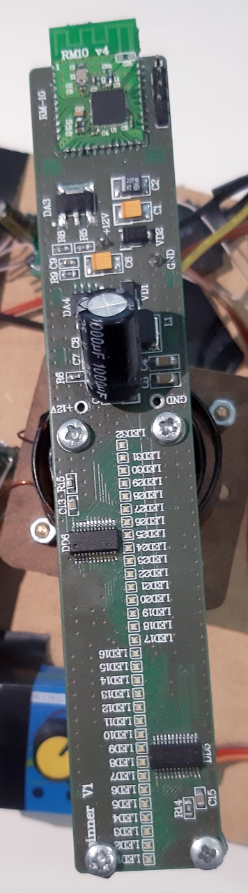
Top side of the board
With the optical sensor, the image is clear, but stabilizes in about 30 seconds. This happens for a variety of reasons, one of which is the discreteness of the timer. This is 4 million ticks per second, divided by 360 degrees with the remainder, which introduces distortion into the output image.
In a Chinese stroboscopic watch, the image is set in a couple of seconds at the cost of the fact that a small segment of the circle is simply not displayed: the circular image has an empty spot, it is invisible in the text, but the picture is incomplete.
However, the problems did not end. Microcontroller nRF52832cannot provide the necessary data transfer rate for a possible number of shades (approx. 16 MHz) - the screen produces 1 frame per second, this is not enough for the human eye. Obviously, you need to place a separate microcontroller on the board to control the image, but for now it has been decided to replace MBI5030 with MBI5039 . This is only 7 colors, including white, but this is enough to work out the software part.
Well, it’s also important, for the sake of which this educational task was started - to program the microcontroller and carry out control through the application on the smartphone.
Now the scan is transmitted via Bluetooth directly via nRF Connect, and the application interface is under development.
Thus, the intermediate results of the relay team are as follows:
The rotation screen has a line of 32 LEDs and an image diameter of 150 mm. It displays 7 colors, sets an image or text in 30 seconds (which is not ideal, but acceptable for a start). Via a Bluetooth connection, you can send a command to change the image.
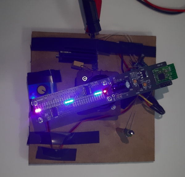
And so it looks.
And for new young developers for successful training it remains to solve the following tasks: To
overcome the lack of RAM in the microcontroller for full-color display of the color palette. Modify the application for the formation and transfer of static or dynamic images. Give the design a finished look. We will keep you posted.
PS Of course, after finishing work on Bluetooth LE ( nrf52832) we will design and implement the Wi-Fi / Bluetooth version on ESP32 But this will be a new story.

A beginner does not have the necessary specialized competencies. Even an experienced specialist has to restructure. The manager is pressured by questions, what tasks should be set for a new employee at the start and what time should be devoted to them? At the same time, ensuring interest, involvement, drive and integration. But do not risk critical business tasks.
For this, we are launching relay internal projects. They consist of independent short stages. The results of such work serve as the foundation for subsequent developments and allow the newcomer to show himself, join the team with an interesting task and without risk filling up an important project. Here is the accumulation of experience, and acquaintance with colleagues, and the opportunity to show oneself from the best side, when there are no strict restrictions on the part of legacy.
An example of such a relay development was the theme of a rotational screen based on a stroboscopic effect with the possibility of displaying an arbitrary user dynamic image made on the phone screen onto it . Prototypes can be found here .
The work was carried out sequentially by several employees and will be continued by new ones during their onboarding (from two weeks to a month depending on the abilities and level of competencies) ..
The steps were as follows:
a) to think over the design (having studied the available samples, description of analogues, showing creative initiative);
b) develop a circuit diagram, dissolve it on the board;
c) develop a protocol for transferring the image from the phone to the device;
d) provide control from a smartphone via Bluetooth LE.
The starting option was to use something very compact, such as a three-leaf spinner, which, when manually rotated, began to show inscriptions. The BLE module was located in one lobe, ten RGB-LEDs in the second, an optical sensor in the third, and a battery in the center. A circuit diagram was drawn up and the first experiments were conducted. It became clear that the picture quality level is very low, the resolution is small, the game effect is short-lived, the possibilities are modest. Yes, and spinners are gone as quickly as they appeared. It was decided to raise the bar and develop a rotary stroboscopic screen. At least it can be used for practical purposes at exhibitions and conferences and in the near future interest in such solutions will not disappear.
Regarding the design, there were two main questions: how to arrange the LEDs (in a vertical plane, as in the example above or in horizontal) and how to power a rotating board with LEDs.
For educational purposes, the LEDs were located only in a horizontal plane. As for the board's power supply, there was an important choice: either we take the collector motor bulky, noisy, but cheap, or we use a more elegant solution with non-contact power transmission using two coils - one on the engine and the other on the board. The solution, of course, is elegant, but more expensive and longer, because coils had to be calculated first, and then wound (preferably not on the knee).
It looks like the resulting prototype
The specifics of mass production is such that every extra cent in cost is of importance. Success can be determined by the cost of a handful of passivation. Therefore, it is often necessary to choose a less effective, but cheaper option, so that the manufacturer can maintain commercial competitiveness. Therefore, imagining that the rotation screen will be launched into mass production, the developer chose a commutator motor.
The resulting prototype sparkly sparkled at the start, made noise and shook the table. The design that ensured stability turned out to be so heavy and dimensional that it did not make sense to bring it to a serial prototype. Rejoicing for the intermediate success, they decided to replace the engine with a rotating transformer with an air gap. Another reason was the inability to power the engine from the computer's USB port.
The basis of the LED board was our RM10 module and six MBI5030 LED drivers .
Drivers have 16 channels with the ability to independently control each. Thus, 6 such drivers and 32 RGB LEDs in total have the ability to show 16 million colors.
To synchronize and stabilize the output image, two MRSS23E magnetoresistive Hall sensors were used .
The plan was simple - the sensor gives an interrupt for each turn of the board, according to the clock between the two passes, the position of the LEDs is determined and their azimuth and glow in the 360 degree scan are calculated.
But something went wrong - regardless of the board rotation speed, the sensor randomly gave out one or two interrupts per pass. Thus, the image turned out to be blurry and folded inward.
Replacing the sensors did not change the situation, so the Hall sensor was replaced with a photoresistor.
Who has thoughts why the magnetoresistive sensor could behave like this, share in the comments.
Top side of the board
With the optical sensor, the image is clear, but stabilizes in about 30 seconds. This happens for a variety of reasons, one of which is the discreteness of the timer. This is 4 million ticks per second, divided by 360 degrees with the remainder, which introduces distortion into the output image.
In a Chinese stroboscopic watch, the image is set in a couple of seconds at the cost of the fact that a small segment of the circle is simply not displayed: the circular image has an empty spot, it is invisible in the text, but the picture is incomplete.
However, the problems did not end. Microcontroller nRF52832cannot provide the necessary data transfer rate for a possible number of shades (approx. 16 MHz) - the screen produces 1 frame per second, this is not enough for the human eye. Obviously, you need to place a separate microcontroller on the board to control the image, but for now it has been decided to replace MBI5030 with MBI5039 . This is only 7 colors, including white, but this is enough to work out the software part.
Well, it’s also important, for the sake of which this educational task was started - to program the microcontroller and carry out control through the application on the smartphone.
Now the scan is transmitted via Bluetooth directly via nRF Connect, and the application interface is under development.
Thus, the intermediate results of the relay team are as follows:
The rotation screen has a line of 32 LEDs and an image diameter of 150 mm. It displays 7 colors, sets an image or text in 30 seconds (which is not ideal, but acceptable for a start). Via a Bluetooth connection, you can send a command to change the image.
And so it looks.
And for new young developers for successful training it remains to solve the following tasks: To
overcome the lack of RAM in the microcontroller for full-color display of the color palette. Modify the application for the formation and transfer of static or dynamic images. Give the design a finished look. We will keep you posted.
PS Of course, after finishing work on Bluetooth LE ( nrf52832) we will design and implement the Wi-Fi / Bluetooth version on ESP32 But this will be a new story.