OBD2 reader - car diagnostics
When creating the application, we were faced with many choices, problems, and so on, with which we will try to acquaint you in this article. As it turned out, you can have a dialogue with the car, and quite productive. Naturally, in order to organize communication with the car, you need to "establish contact", "ask the right question" and correctly understand the "answer" received from the car. Accordingly, the article will be aimed at explaining the organization of the dialogue in an accessible language, as well as telling you what mistakes you might encounter along the way and how to deal with them.
Initially, it is necessary to clarify that an ELM327 adapter will be used to connect to the car. ELM327 is a microcircuit that allows you to convert the protocols used in the diagnostic tires of cars into the RS232 protocol, to which we will transfer data. Due to the fact that data transmission via the RS232 protocol occurs consecutively, the first problem arises - the data transfer speed, which we will try to circumvent in one of the following paragraphs.
There are several variations of the ELM327 adapter, which are classified by the method of data transfer - Bluetooth, WIFI, USB. Based on the fact that the development goal is a mobile device running Android, you can choose the two most suitable versions of ELM327, such as Bluetooth and WIFI. Since there is only one way to receive and process data, and they differ only in connection options to the adapter, you can choose only one, organize a dialogue with it, and then add the remaining connection options.
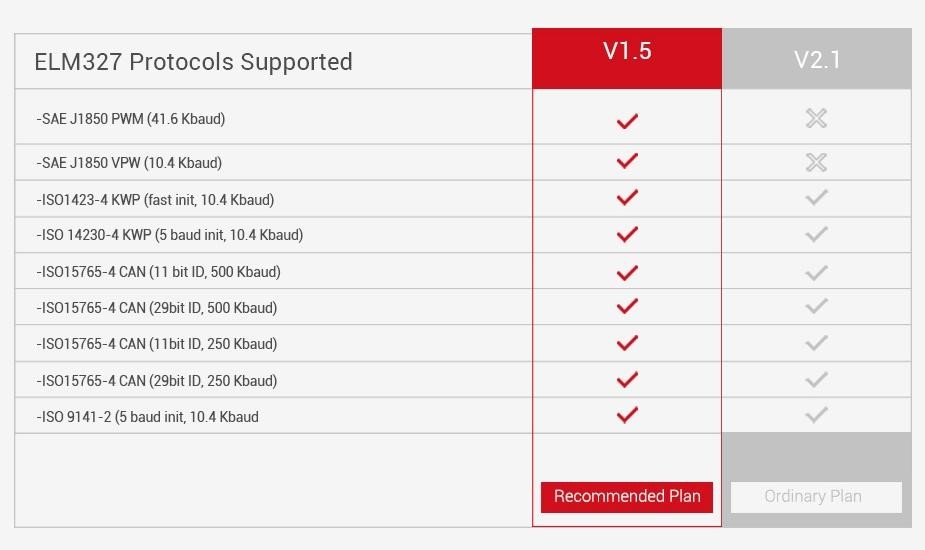
One of the first problems that you could encounter was the problem of choosing the adapter directly, in our case Bluetooth. It turns out that if you need to support all (at least most) cars, you need to choose version v1.5 instead of v2.1, which in fact needs to be clarified several times when buying an adapter, because sellers try to give out the adapter version not for the one that is in fact, because they are not particularly different. In fact, in version v2.1 there is no support for the J1850 PWM and J1850 VPW protocols, which means that you will not be able to connect to cars that use these protocols.
Connecting to the adapter takes place in several stages:
If everything is clear with the organization of the connection. The principle of operation is the same as with any Bluetooth / WIFI chat. In order to understand how to send the initialization string, it is necessary to study what commands exist, as well as what functions they perform.
AT Z [reset all]
Resets the adapter to the factory state.
AT L1-0
Enable / Disable linefeeds.
AT E1-0
Echo on - off
AT H1-0
Headers on - off
AT AT0-1-2
Adaptive Timing Off - adaptive Timing Auto1 - adaptive Timing Auto2
AT ST FF
Set the timeout to maximum.
AT D [set all to Default]
Resets the settings to the initial user-configured state.
AT DP [Describe the current Protocol] The
scanner is able to independently determine the protocol of the vehicle to which it is connected.
AT IB10 [set the ISO Baud rate to 10400]
The command sets the data rate for ISO 9141-2 and
ISO 14230-4 10400
AT IB96 [set the ISO Baud rate to 9600]
The command sets the data rate for ISO 9141-2 and
ISO 14230-4 9600 for protocols 3,4,5.
AT SP h [Set Protocol h]
Command for selecting the protocol h, where h:
0 - Automatic;
1 - SAE J1850 PWM (41.6 Kbaud);
2 - SAE J1850 VPW (10.4 Kbaud);
3 - ISO 9141-2 (5 baud init, 10.4 Kbaud);
4 - ISO 14230-4 KWP (5 baud init, 10.4 Kbaud);
5 - ISO 14230-4 KWP (fast init, 10.4 Kbaud);
6 - ISO 15765-4 CAN (11 bit ID, 500 Kbaud);
7 - ISO 15765-4 CAN (29 bit ID, 500 Kbaud);
8 - ISO 15765-4 CAN (11 bit ID, 250 Kbaud);
9 - ISO 15765-4 CAN (29 bit ID, 250 Kbaud);
AT SP Ah [Set Protocol h with Auto]
The command sets the default protocol h, if the connection via protocol h failed, then the adapter starts automatic protocol selection.
Based on the commands described above, we form the initialization string.
It is advisable to enable the user to change the initialization commands, because in order to select the “key” for some cars, it is necessary to choose more suitable adapter settings. In our case, settings are used that are suitable for most standard protocols.
It is also advisable to pay attention to the APSP0 command, so we set the default automatic protocol selection, this may take some time.
Accordingly, if the user knows what his auto protocol is, then using the ability to change the connection protocol, he can change 0 to his protocol number.
PID's special commands are used to read diagnostic data.
PID (Parameter id's - On-board Diagnostic Parameter Identifiers) - codes that are used to query the performance of specific vehicle sensors.
The main pids can be found on Wikipedia, there is a complete set of basic commands that all cars should support. There are also sets of commands for certain brands and types of cars, these sets are provided for a fee. In our case, the application is focused on the basic diagnostics of cars, respectively, we use the basic set of commands.
It is also possible to receive current data from the car, while the command to receive data from the car will have first 01, indicating that we want to get real data. If we want to get the saved car data, then at the beginning of the command you must specify 02 . For example, the command to get the current speed of the car is 010D , and to get the saved speed - 020D .
If you carefully look at the number of commands that are provided by open resources, you can just notice the problem that I wrote about at the very beginning, namely the problem of adapter response speed. Since sending and receiving commands is sequential, in order to receive sensor readings at the current time, it is necessary to wait for an answer to all previous commands. Accordingly, if you request to receive all the commands, then there is a high probability that the update of real data will occur very slowly. But this problem can be solved if you use the commands that display only those teams that exist in the car. For example:
0100 - PIDs supported [01 - 20]
0120 - PIDs supported [21 - 40]
0140 - PIDs supported [41 - 60]
0160 - PIDs supported [61 - 80]
0180 - PIDs supported [81 - A0]
01A0 - PIDs supported [A1 - C0]
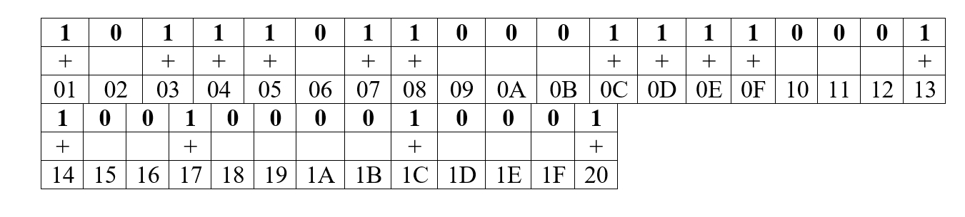
I will demonstrate how to determine which sensors are present in the car using one of the pids. For instance:
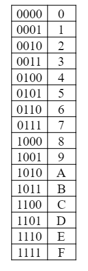
We translate the answer from the car into a binary number system
Using the following plate, we can determine which pids are supported by our car, starting from 01 to 20:
Based on the data obtained, we can determine that our car supports the following pids:
Now, instead of sending all 32 teams and waiting for an answer to them, despite the fact that some may be absent, we will use only 15 teams. But this is not the limit of the so-called optimization. In order for the data to be updated even faster, I advise you to request only data about those sensors that are displayed on the screen. Although this limits some functionality of the application. For example, a history record.
Car errors can also be different and separate commands exist for them too. For instance:
As with other commands, car errors come in encoded form, respectively, as in other commands, they need to be decoded to get the necessary information. Let me give you an example of how error decoding works. The code:
And now for the explanation.
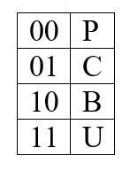
Based on the received response, we can get an error code, for this we decode the received message using the following plates.
First character:
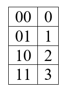
Second character:
3, 4, 5 characters are formed according to this table:
Based on this, we can try to parse the following answer 0001000000111110 Error
code: P103E
At this stage, we figured out how to organize a dialogue with the adapter, send commands to it, receive and decrypt its answers. This is a large part of the work, if you consider how much time it takes to study the material, but at the same time quite interesting. Outside of this article, there are many problems associated with the visual interface, as well as many additional functions, such as adding new pids from a file, a standard and advanced way to connect to the adapter and create graphs.
Matvienko Alexander, Hossein Fakhr.
Connection Choice
Initially, it is necessary to clarify that an ELM327 adapter will be used to connect to the car. ELM327 is a microcircuit that allows you to convert the protocols used in the diagnostic tires of cars into the RS232 protocol, to which we will transfer data. Due to the fact that data transmission via the RS232 protocol occurs consecutively, the first problem arises - the data transfer speed, which we will try to circumvent in one of the following paragraphs.
There are several variations of the ELM327 adapter, which are classified by the method of data transfer - Bluetooth, WIFI, USB. Based on the fact that the development goal is a mobile device running Android, you can choose the two most suitable versions of ELM327, such as Bluetooth and WIFI. Since there is only one way to receive and process data, and they differ only in connection options to the adapter, you can choose only one, organize a dialogue with it, and then add the remaining connection options.
ELM327 1.5 vs ELM327 2.1
One of the first problems that you could encounter was the problem of choosing the adapter directly, in our case Bluetooth. It turns out that if you need to support all (at least most) cars, you need to choose version v1.5 instead of v2.1, which in fact needs to be clarified several times when buying an adapter, because sellers try to give out the adapter version not for the one that is in fact, because they are not particularly different. In fact, in version v2.1 there is no support for the J1850 PWM and J1850 VPW protocols, which means that you will not be able to connect to cars that use these protocols.
Connection
Connecting to the adapter takes place in several stages:
- Connecting to an adapter (Bluetooth, WIFI)
- Sending initialization commands (initialization string)
If everything is clear with the organization of the connection. The principle of operation is the same as with any Bluetooth / WIFI chat. In order to understand how to send the initialization string, it is necessary to study what commands exist, as well as what functions they perform.
AT Z [reset all]
Resets the adapter to the factory state.
AT L1-0
Enable / Disable linefeeds.
AT E1-0
Echo on - off
AT H1-0
Headers on - off
AT AT0-1-2
Adaptive Timing Off - adaptive Timing Auto1 - adaptive Timing Auto2
AT ST FF
Set the timeout to maximum.
AT D [set all to Default]
Resets the settings to the initial user-configured state.
AT DP [Describe the current Protocol] The
scanner is able to independently determine the protocol of the vehicle to which it is connected.
AT IB10 [set the ISO Baud rate to 10400]
The command sets the data rate for ISO 9141-2 and
ISO 14230-4 10400
AT IB96 [set the ISO Baud rate to 9600]
The command sets the data rate for ISO 9141-2 and
ISO 14230-4 9600 for protocols 3,4,5.
AT SP h [Set Protocol h]
Command for selecting the protocol h, where h:
0 - Automatic;
1 - SAE J1850 PWM (41.6 Kbaud);
2 - SAE J1850 VPW (10.4 Kbaud);
3 - ISO 9141-2 (5 baud init, 10.4 Kbaud);
4 - ISO 14230-4 KWP (5 baud init, 10.4 Kbaud);
5 - ISO 14230-4 KWP (fast init, 10.4 Kbaud);
6 - ISO 15765-4 CAN (11 bit ID, 500 Kbaud);
7 - ISO 15765-4 CAN (29 bit ID, 500 Kbaud);
8 - ISO 15765-4 CAN (11 bit ID, 250 Kbaud);
9 - ISO 15765-4 CAN (29 bit ID, 250 Kbaud);
AT SP Ah [Set Protocol h with Auto]
The command sets the default protocol h, if the connection via protocol h failed, then the adapter starts automatic protocol selection.
Based on the commands described above, we form the initialization string.
initializeCommands
        = Arrays.asList("ATZ", "ATL0", "ATE1", "ATH1", "ATAT1", "ATSTFF", "ATDP", "ATSP0");
It is advisable to enable the user to change the initialization commands, because in order to select the “key” for some cars, it is necessary to choose more suitable adapter settings. In our case, settings are used that are suitable for most standard protocols.
It is also advisable to pay attention to the APSP0 command, so we set the default automatic protocol selection, this may take some time.
Accordingly, if the user knows what his auto protocol is, then using the ability to change the connection protocol, he can change 0 to his protocol number.
Read diagnostic data
PID's special commands are used to read diagnostic data.
PID (Parameter id's - On-board Diagnostic Parameter Identifiers) - codes that are used to query the performance of specific vehicle sensors.
The main pids can be found on Wikipedia, there is a complete set of basic commands that all cars should support. There are also sets of commands for certain brands and types of cars, these sets are provided for a fee. In our case, the application is focused on the basic diagnostics of cars, respectively, we use the basic set of commands.
It is also possible to receive current data from the car, while the command to receive data from the car will have first 01, indicating that we want to get real data. If we want to get the saved car data, then at the beginning of the command you must specify 02 . For example, the command to get the current speed of the car is 010D , and to get the saved speed - 020D .
If you carefully look at the number of commands that are provided by open resources, you can just notice the problem that I wrote about at the very beginning, namely the problem of adapter response speed. Since sending and receiving commands is sequential, in order to receive sensor readings at the current time, it is necessary to wait for an answer to all previous commands. Accordingly, if you request to receive all the commands, then there is a high probability that the update of real data will occur very slowly. But this problem can be solved if you use the commands that display only those teams that exist in the car. For example:
0100 - PIDs supported [01 - 20]
0120 - PIDs supported [21 - 40]
0140 - PIDs supported [41 - 60]
0160 - PIDs supported [61 - 80]
0180 - PIDs supported [81 - A0]
01A0 - PIDs supported [A1 - C0]
I will demonstrate how to determine which sensors are present in the car using one of the pids. For instance:
- 0100 \\ request
- BB1E3211 \\ answer from the car
We translate the answer from the car into a binary number system
BB1E3211(16) > 10111011000111100011001000010001(2)Using the following plate, we can determine which pids are supported by our car, starting from 01 to 20:
Based on the data obtained, we can determine that our car supports the following pids:
01, 03, 04, 05, 07, 08, 0C, 0D, 0E, 0F, 13, 14, 17, 1C, 20Now, instead of sending all 32 teams and waiting for an answer to them, despite the fact that some may be absent, we will use only 15 teams. But this is not the limit of the so-called optimization. In order for the data to be updated even faster, I advise you to request only data about those sensors that are displayed on the screen. Although this limits some functionality of the application. For example, a history record.
Reading and decoding car errors
Car errors can also be different and separate commands exist for them too. For instance:
- 03 - To display saved error codes
- 0A - To display persistent error codes.
As with other commands, car errors come in encoded form, respectively, as in other commands, they need to be decoded to get the necessary information. Let me give you an example of how error decoding works. The code:
private final static char[] dtcLetters = {'P', 'C', 'B', 'U'};
private final static char[] hexArray = "0123456789ABCDEF".toCharArray();
private void performCalculations(String fault) {
    final String result = fault;
    String workingData = "";
    int startIndex = 0;
    troubleCodesArray.clear();
    try {
        if (result.contains("43")) {
            workingData = result.replaceAll("^43|[\r\n]43|[\r\n]", "");
        } else if (result.contains("47")) {
            workingData = result.replaceAll("^47|[\r\n]47|[\r\n]", "");
        }
        for(int begin=startIndex; begin < workingData.length(); begin += 4) {
            String dtc = "";
            byte b1 =
		    Utility.hexStringToByteArray(workingData.charAt(begin));
            int ch1 = ((b1 & 0xC0) >> 6);
            int ch2 = ((b1 & 0x30) >> 4);
            dtc += dtcLetters[ch1];
            dtc += hexArray[ch2];
            dtc += workingData.substring(begin + 1, begin + 4);
            if (dtc.equals("P0000")) {
                continue;
            }
            troubleCodesArray.add(dtc);
        }
    } catch (Exception e) {
        Log.e(TAG, "Error: " + e.getMessage());
    }
}
And now for the explanation.
Based on the received response, we can get an error code, for this we decode the received message using the following plates.
First character:
Second character:
3, 4, 5 characters are formed according to this table:
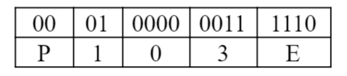
Based on this, we can try to parse the following answer 0001000000111110 Error
code: P103E
Epilogue
At this stage, we figured out how to organize a dialogue with the adapter, send commands to it, receive and decrypt its answers. This is a large part of the work, if you consider how much time it takes to study the material, but at the same time quite interesting. Outside of this article, there are many problems associated with the visual interface, as well as many additional functions, such as adding new pids from a file, a standard and advanced way to connect to the adapter and create graphs.
Matvienko Alexander, Hossein Fakhr.