Explaining the physical essence of the Wing Lift phenomenon without using the Bernouli equation. Part 2
- Tutorial
- Recovery Mode
Wing lift. Part 2
Ilya Alekseevich Monin, Ph.D., imoninpgd@gmail.com
To understand the development of "aviation" as an industry and "aerodynamics" as a science, you need to remember that first appeared the first aircraft built by on-the-spot engineers (see fig.11), and only then theorists began to emerge who created the discipline “Aerodynamics” based on the results of the creation of design engineers.
In the picture is a plane created by motorist Henri Farman by remaking a purchased small-scale Voisen plane. At the same time, the original aircraft of the Vuazen brothers began to be produced only in 1907. At the time of purchase by Farman, the airplanes of Voisin could only jump slightly and fly several dozen meters. Farman, after a series of alterations of the original aircraft, made it possible to fly more than 1000m, while still turning around and, after making a circle, land. There was a record flight Farman January 13, 1908. And in 1909, the Farman Brothers firm opened its own production of airplanes of its own design and a flight school for teaching the art of flying on them (see figure 12). The flight speed of the Farman aircraft was then about 60 km / h, which was shown in a record flight at a distance of 180 km, overcome in 3 hours of flight.

Fig.11. Layout of the aircraft of Voisin, converted to a record flight of Farman in 1907-1908.


Fig.12. Layout of the aircraft "Farman IV-1910." In the museum, and a photo of the original sample at the airport.
It is clear that the first early aircraft were thin, light and low-speed.
These are the parameters that correspond to the first convex-concave thin profiles, more similar to the simplest curved sheet of plywood, and not to a complex profile with a deep theoretical miscalculation.
For reference, I give an illustration of the transformation of wing profiles from the earliest beginning of the 20th century, to the fully developed aircraft industry of the mid 40s. (see

figure 13) Fig.13. Trends in the profile of the wing of the aircraft of the first half of the 20th century.
After the first light experimental aircraft was followed by a rapid increase in the size and weight of aircraft for the transport of ever-increasing payload. Thin wings could not withstand such a scale and weight, which required installing high strong beams inside the wing, and making the wing itself flat-convex or even double-convex in order to hide the supporting beam behind the streamlined wing hem.
Already in the 20s, all wing profiles took quite a modern look.
By the 1940s, the aviation industry had developed so much that it began to produce whole armada of airplanes capable of carrying entire cities into the dust of the air. But with such an explosive development of production capacity, the theoretical base remained extremely weak.
By the 1930s, the intensity of aviation development did not allow building new aircraft according to “intuition”, but required the construction of a powerful experimental base for blowing out parts of airplanes, large-scale mock-ups and airplanes entirely on the ground in huge wind tunnels (ADT).
So in TsAGI in 1939, the largest at that time (the second in the world now) wind tunnel T-101 was launched, which allowed to explore on the ground entirely on actual flight speeds at that time.
Flow rate 5–52 m / s
Number of Re per 1 m to 3.6 ∙ 106
Total atmospheric pressure
Speed head up to 1.7 kPa
Ambient deceleration temperature
Angle of attack range (α) ± 20 °
Slip angle range (β) ± 180 °
Dimensions of the working part :
Nozzle section (ellipse) 24x14 m
Length of the working part 24 m
Dimensions of test objects:
Wingspan: up to 18 m
Fuselage length: up to 30 m
Wing area: up to 35 m2
Since then, the airplanes have become much larger, and the flight speeds are much faster, so that not a single modern aircraft fits into the T-101 ADT entirely, and in more modern and more high-speed ADTs they only blow large-scale dummies or structural elements separately.
True, in theory, since the beginning of the last century, little has changed, so that already at the end of the twentieth century, aircraft designers began to reinvent what designers in the early to mid-20th century had passed, but theorists did not explain. For example, let me give a view of the profile of the wing of the aerobatic aircraft, which was considered the best back in the 1980s (see figure 14).

Fig.14. One of the wing profiles from the Aviation Profiles catalog.
The same return motion of thought is observed among large samples of flight technology, this was reflected in the creation of WIG monsters in the 1960s and 80s (Fig. 15), which are little distinguishable from the giant planes of the late 1930s (Fig. 16).
At the same time, the screen effect itself was discovered as early as the beginning of the 30s at the moments of landing large multi-engined airplanes with a large wing chord.
The same screen effect clearly manifested itself when landing a record long-range ANT-25 aircraft, when, during a test flight in 1933, the plane simply could not land, and with a light touch of the wheels of the ground, the plane bounced and took off again. In order to remove this effect and ensure a smooth landing, it was even necessary to install special retractable brake flaps, which sharply worsen the flight performance of the wing during landing.
The wing chord in the widest root part of the ANT-25 exceeded the height of the landing gear, thus creating ideal conditions for the formation of a screen effect under a wide low-flying wing. Moreover, during landing with empty tanks with an aircraft mass of 4000 kg and a wing area of 88 square meters, the average load on the wing in flight was less than 50 kg / square meter, which corresponds to the velocity head 500 Pa created at a speed of 104 km / h (29 m / s) for flying on the screen. It is worth noting that the aircraft of that time flew extremely slowly (by modern standards), so the record ANT-25 had a cruising speed of about 165 km / h (max. 266 km / h at height), with a flight range of 10-12 thousand km and a duration of 75- 80 hours in a row.
A.

B.

C.

Figure 15. The ekranoplan "Caspian Monster": a.) In flight. B.) Stationary on the water full face. c.) Motionless in frontal projection.
A.

B.


Fig.16. Giant ANT-20 "Maxim Gorky", 1939. a) Schematic section. B) Photos at the airport and during landing.
Stagnation zones in air flow around bodies of complex shape as a tool for forming a virtual wing profile.
Often there are cases. When it is necessary to build airflow lines around bodies, the shape of which is difficult to call streamlined.
It is clear that the air will not obediently wrap around all the corners and notches of the body, but will go in soft twists, sweeping over the pits and filling them with vortices of detached streams of stagnant zones.
If we consider the presence of stagnant zones as additional solid volumes of the profile itself, then the flow around the aerodynamic elements known to us will take a completely different look.
Interestingly, this method of finding the equivalent conditional prototype wing is used in existing applied Aerodynamics. In any case, the method of constructing a “Fictitious semi-infinite body” around a rigid wing is described in the textbook [3] for three whole pages (pp. 435-437), while the border of the fictitious wing is chosen as the border of the thick inhibited boundary layer our very stagnant zones in “tear-off bubbles” or turbulent zones with a complete disruption of the flow above the wing. The pressure on the solid wing from the high-speed air flow is considered equal to the pressure of this flow on the “fictitious body”. It turns out that the pressure is transferred from the high-speed jet to the solid wing through a sufficiently thick layer of slow-moving air of the boundary inhibited layer (stagnant zone) without any distortion.
Let us consider in detail the process of soft flow around high-speed jets of varying intensity of wing profiles and select various “stagnant zones”.
The case of complete sticking of the flow to the wing at small angles of attack does not add much novelty (see figure 17), but a small stagnant zone appears on the front fairing, resembling a small sharp beak on a round bird head.
The element seems small, but it is extremely important to understand the phenomenon of “flow” in general.
Consider the usual profile of the wing in horizontal flight with pronounced tear-off jets, first with a zero angle of attack (see figure 18), and then the same wing is already at a large angle of attack (see figure 20).

Fig.17. The profile of the wing with a flow without breaks on the planes of the wing, but with a small zone of complete deceleration of the flow on the forward part of the wing.
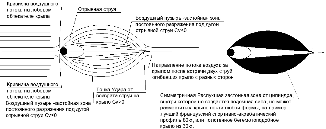
Fig.18. The profile of the wing with the separation of flows on the planes of the wing at zero angle of attack and its “Fictitious body”.
Looking at the strong increase in the “Fictitious body” in comparison with the original pushing front fairing, it becomes clear how surprisingly low frontal resistance is obtained for long spindly bodies, for example, in aircraft fuselage.
The streamlining of such forms reaches Cx = 0.06, whereas for a ball of the same section Cx = 0.4..0.5, and for a flat plate Cx = 1.
It turns out that in the discharge under the tearing jets in the frontal projection, the resistance is not created at all. It remains only to land the tear-off jet on a straight surface parallel to the velocity vector so that the impact does not produce a longitudinal to velocity component. With such a task, the long cylindrical fuselage with an elongated, ovoid front fairing perfectly copes. It turns out that the frontal resistance of a huge fuselage is equal to the resistance of the ball at the tip of the tapering nose (see figure 19.)
The ratio of the diameter of the ball in the nose cone to the diameter of the fuselage depends on the speed of flight, and the higher the speed of flight, the narrower the nasal rounding becomes, pushing the air flow apart. The increasing energy of the oncoming flow with a constant amount of frontal section requires scattering less and less air to the side of the fuselage while maintaining a constant section of the “fictitious body” behind the fairing. In supersonic, the radius of curvature of the nose fairing degenerates into the tip, but this is a completely different story.
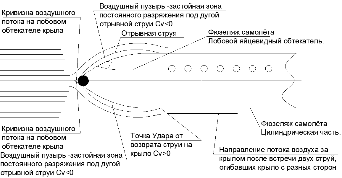
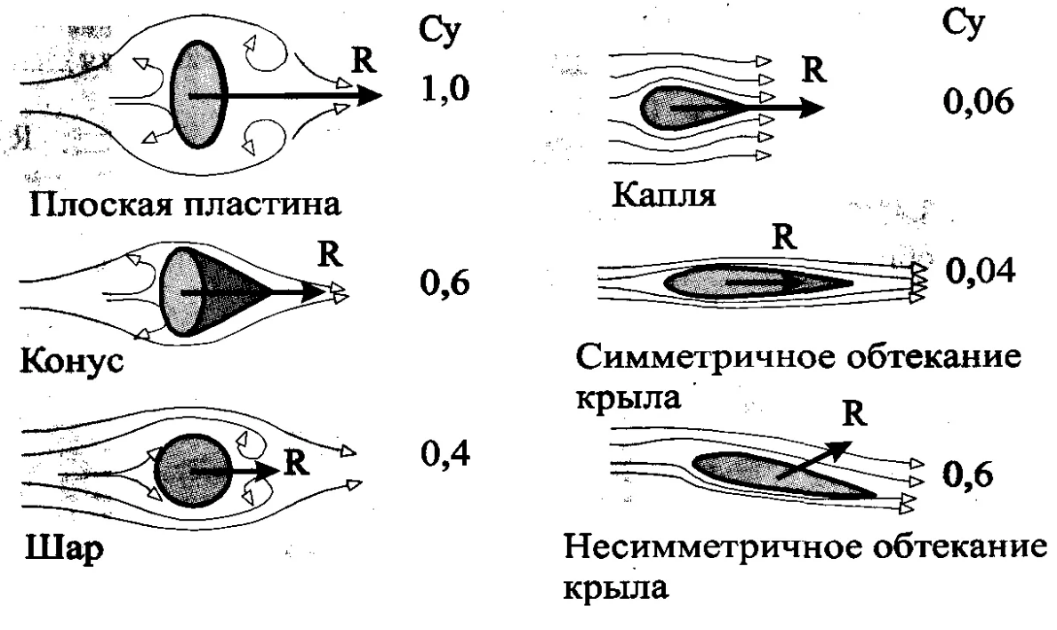

Fig. 19. Wrap around the fuselage with tear-off jets, under which creates a zone of zero resistance to flight. All the resistance of the fuselage is equal to the aerodynamic resistance of the ball in its nose fairing. And accompanying illustrations from textbooks on the theme of resistance when air flows around various bodies.
Now consider the behavior of the detachable turbulent zones with a wing with a large angle of attack (see Figure 20).
First, it is necessary to trace the trajectory of the detachable flow above the stagnant zone before meeting with the flow from under the wing of the aircraft. Since the profile of the frontal fairing of the wing is considered symmetrical cylindrical, the detachable jets have equal power and trajectory, that is, they are also symmetric.
For the horizontal wing, we have already received a symmetrical two-sided detachable bubble with the closure of the jets on the wing in the same places.
When giving the wing a large angle of attack, the pattern of tear-off jets changes. At the same time, the dimensions of the “Separated bubbles” = “Stagnant zones” above and below the wing begin to differ dramatically in volume.
As a result, as a “fictitious body”, a very swollen wing will be obtained with a significant flattening of the lower plane compared to the huge dome of the tear-off bubble on the upper plane of the wing. Interestingly, the equivalent virtual profile of the “fictitious body” at a large angle of attack of the wing with swollen tear-off bubbles on the upper plane of the wing is surprisingly similar to the famous EKIP aircraft. (see figure 21 )

Figure 20. The profile of the wing with the separation of flows on the planes of the wing at a high angle of attack and its "Fictitious body".


Fig.21. Ekranoplan EKIP. The layout of the perspective model of the Ekranoplan and the existing umenshchennaya model of the Ekranoplan (never taken off because of the project shutdown).
That is, in the EKIP Ekranolet, quite a sensible idea was offered to control the stagnant zone in the rear "shadow" part of the hull, which allowed the detachment jet to settle on the wing in the upper part of the dome, which gives greater lifting force and reduces aerodynamic resistance to flight.
It turns out that the author of the EKIP was not such an inventor, offering such a hippo-like structure as an aircraft.
True, the EKIP should not fly very fast and at large angles of attack of the initial thin profile (about 15 degrees), with a correspondingly high frontal resistance.
The sheer volume of cargo space in such a flying wing can more than compensate for some deterioration in aerodynamics. At the same time, a structurally planeless Aircraft-Wing looks much more attractive than a traditional aircraft with a separation of the functions of the thin “carrier wing” and “cargo-passenger fuselage”. That's just for a stable flight, you still have to add a long beam to accommodate the tail, as on the giant flying wing of the ANT-20 "Maxim Gorky."
A significant expansion of the wing (increase in the chord) makes the EKIP-type Aircraft also clearly pronounced the Ekranoplan in its aerodynamic properties when flying near the ground. So, when flying on the screen, the “fictitious body” of the wing with a large angle of attack transforms into a strange iron, where the small nasal beak of the stagnation zone on the wing inflates to the size of a huge stagnant wedge under the wing (see figure 22).
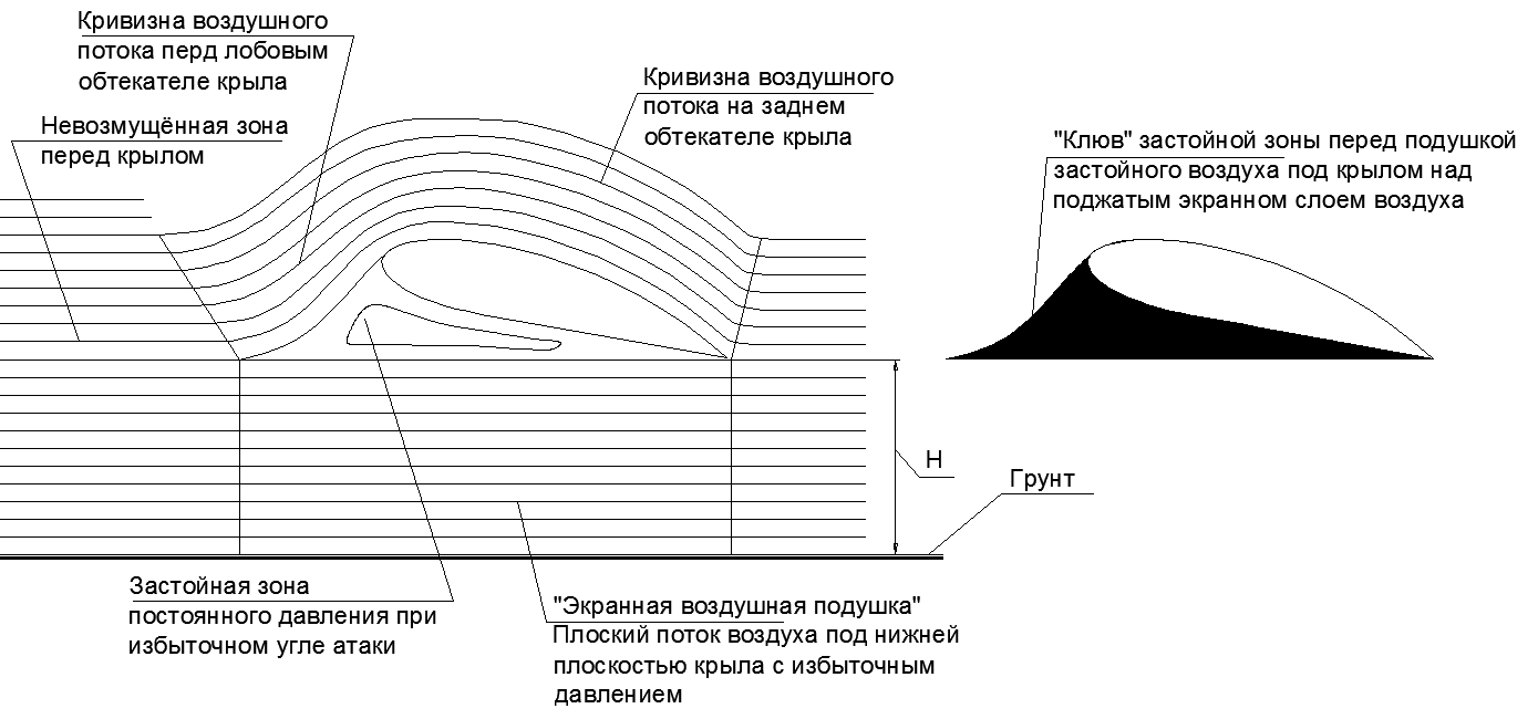
Fig.22. The profile of the wing when flying above the screen at a large angle of attack and its "phantom body".
Inside this sharp-nosed iron can be placed as profiles of EKIP and VBA-14 (Bartini) EKRANOLETs, or a super-thick wing like that of ANT-20 “Maxim Gorky”.
Airplanes with a very thick wing were popular in the 1930s in the USSR, when the largest pre-war ANT-20 “Maxim Gorky” aircraft was created. This aircraft had a wing so thick and wide that several cabins were placed in the root compartments of the wing, where a person walked to his full height (see Fig. 16.).
True, this monster flew with a cruising speed of only 198km / h (maximum 220km / h).
If the ANT-20 slightly shortens the wing ends, leaving only the central thickest part, the plane will look like Rostislav Alekseev, the later Caspian Monster Ekranoplan.
It is interesting to compare similar in size "Maxim Gorky" from the 1930s with the "Caspian Monster" from the 60s (see table 5)
Tab.5. Comparative characteristics of the ANT-20 "Maxim Gorky" 1934. and Ekranoplan CM "Caspian Monster" 1966.
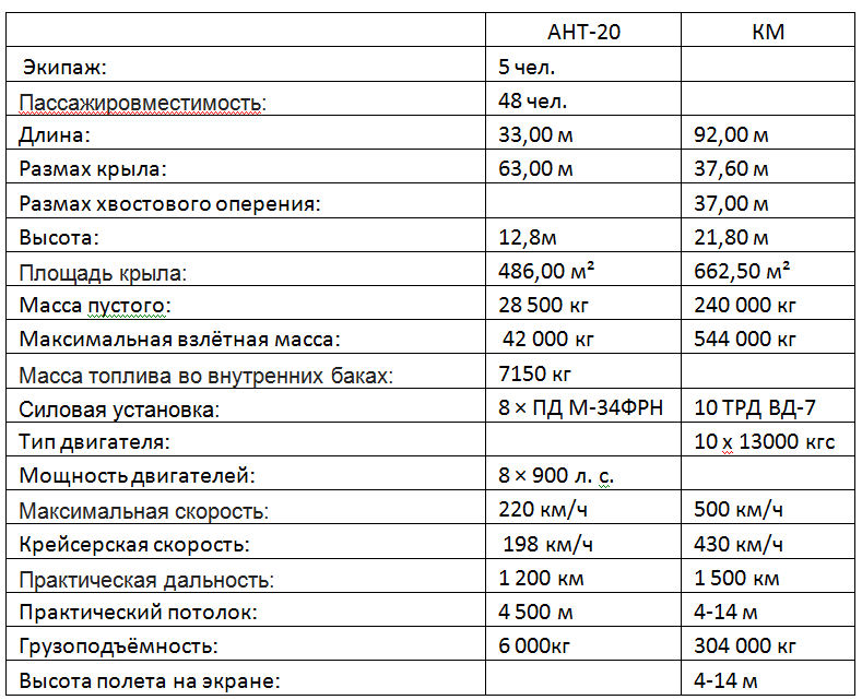
The table presents reference data that must be somehow interpreted.
Let's go first simple by direct comparison of homogeneous numbers by dividing each other.
Maximum weight: 544/42 = 13 times
Wing area: 662/486 = 1.36 times
Specific load on the wing: 13 / 1.36 = 9.5 times
Cruising speed:
430/198 = 2.17 times Difference in velocity head cruising speed: 2.17 ^ 2 = 4.71 times
Power of power installations: (10 * 1300 * 9.81 * 430 / 3.6) / (8 * 900 000 * 0.735) = 28.8 times
Payload based on fuel: 304 / (42-28.5) = 22.51.
Practical range: 1500/1200 = 1.25
The ratio of fuel efficiency ANT-20 = 7150 / (1200 * 6) = 0.993 l / (t * km) The
gluttony of the CM is not known, but it can be estimated through power and speed.
When calculating the specific consumption for reference gluttony 0.8kg / (kgf * h) for the VD-7 TRD engine.
The consumption of afterburner during acceleration from water is 10 * 13000 * 0.8 = 104 000 kg / h.
Considering the duration of a cruise flight on the screen with only two working engines out of ten available for acceleration and exit to the Screen, the efficiency will increase.
For a cruise flight with two engines 2 * 13 000 * 0.8 = 20 800 kg / h
Flight time 1500/430 = 3.5 hours
During the flight to the maximum range of 1500 km, the CM will eat at least 104 * 0.5 + 3.5 * 20.8 = 100 tons of fuel.
And the payload will be about 200 tons.
Fuel economy KM will get 100 000 / (1500 * 200) = 0.333 l / (t.km).
Conclusions from the obtained ratios:
1. In fuel efficiency, a CM may in the optimistic version prove to be 3 times more economical than ANT-20.
Now, the modern Airbus A380 airliner has a cargo modification A380F with the ability to carry cargo up to 150 tons at a distance of up to 10,370 km. The maximum take-off weight is 560 tons (the mass of the aircraft itself is 280 tons). The calculation of profitability for the cargo version of these indicators makes 130 tons of fuel 150 tons of cargo at a distance of 10370 km: 130000 / (150 * 10370) = 0.0835 l / (t * km).
In terms of passengers, the indicator is different: “Among large liners, the most economical is three liters of fuel per passenger per one hundred kilometers (54 nautical miles) of the route. According to Airbus [5], the A380 burns 17% less fuel per passenger than the “modern largest aircraft” (apparently, the Boeing 747 is meant). “
That is, when checking for 850 passengers with luggage and seats, we will get an indicator close to the calculation for the cargo version.
It turns out that we not only began to fly 4-5 times faster over the past 80 years, but also improved fuel efficiency more than 10 times from the ANT-20 and 4 times from the Ekranoplan KM. Although only 20 years ago, our Airbus flew 5 times faster than ANT-25. The recent decline in speed in passenger aviation has been caused by the struggle for fuel-efficient flight.
2. The cruise speed of the CM is made so high by force, since at a lower speed it simply cannot fly on the screen. The flight condition on the screen is the fulfillment of the inequality “Speed pressure”> “Average load on the wing”, that is,
Pv = 8560Pa at 430km / h (120m / s)> 544000 * 9.81 / 662.5 = 8055Pa.
3. The flight safety of a low-speed Giant Airplane from the 30s is much better than that of an excessively high-speed ground-effect airplane from the 60s, which is almost uncontrollably carried along among slow-moving ships and omnipresent water birds.
4. The cost of operating waterfree by sea ekranoplans is much more expensive than for land high-altitude aircraft. This is due to the excess number of engines needed only to start from the water and exit to the on-screen flight, as well as due to the extreme aggressiveness of sea water when exposed to engines and ekranoplan designs when flying in clouds of splashes from nearby sea waves.
5. For the WGM KM, it is easy to consider the quality of the wing when flying on two engines, equal to the ratio of their thrust to the weight of the wig itself K = 544 / (13 * 2) = 20.9. Thus, the aerodynamic efficiency of a large and heavy Ekranoplan is at the level of efficiency of the best modern large aircraft with a glider quality of the order of K = 18-20.
6. The three-fold gap in efficiency of the KM Ehranoplan with the Airbus 380F remains a mystery for me: Why, with the equal quality of the glider at the Airbus, fuel efficiency is 4 times better?
Or the whole secret lies in the terrible gluttony of the old Soviet turbojet engines in comparison with modern turbofan engines of a high degree of bypass ratio?
Bibliography:
1. "Hydraulics and Aerodynamics", Altshul AD, Moscow, Stroyizdat, 1986.-413s.
2. “Aerodynamics” part 1, N.F. Krasnov, Moscow, Lenand, 2018, -496s.
3. "Aerodynamics", Ed. V. Kalugina, Moscow, Moscow State Technical University, Bauman, 2017, -607с.