NanoCAD Mechanics program development and specification tools
- Tutorial
The main design document in accordance with GOST 2.102-2013 for assembly units, complexes and kits is the specification. On the assembly drawing, many structural elements can be shown simplified and even conditional, but the specification of such a drawing should still uniquely determine the structure of the product and its composition.
Since the nanoCAD Mechanics program is a vertical application for the nanoCAD platform designed for machine-building enterprises, special attention is paid to the tools for creating specifications. In general, the design of specifications, judging by the questions and comments of users on the Nanosoft forum and by e-mail, is a pretty popular topic.
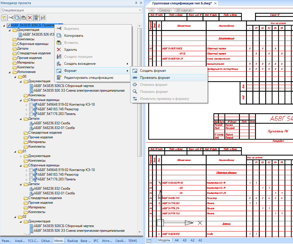
Among the functional panels of the nanoCAD Mechanics program there is the “Project Manager” panel, in which a tree of file specifications is formed (Fig. 1).
A single DWG file can have multiple assembly units with multiple specifications. Before creating a position leader in the “Project Manager”, the necessary assembly unit into which the created position should fall must be marked with the “on” flag.
The specification is also linked to the drawing through the “Project Manager” panel. On any assembly unit, you can right-click on the drop-down list, select “Format” in it, then select “Bind format” and then specify any drawing format for nanoCAD Mechanics. As a result of such a link, the drawing stamp fields can be transferred to the corresponding stamp fields of the specification at the request of the user, the “Designation” field is transferred without the “SB” code, the rest are simply copied.
For the design of the assembly drawing and the corresponding specification in the nanoCAD Mechanics program, two main tools are used: “Position editor” and “Specification editor”. Any changes to the data in the “Position Editor” lead to corresponding changes in the “Specification Editor” and vice versa, that is, these tools are completely synchronized with each other.
If the leader of the specification item is placed on an element of the nanoCAD Mechanics base, then from this element the specification section and the name automatically fall into the leader (Fig. 2). For example, when a position leader is installed on an aviation bolt according to OST 1 31148-80 with an M6 thread and 24 mm long, zinc-plated, such a bolt automatically falls into the “Standard Products” specification section, and the entry “Bolt 6-24-C” is formed in its name - OST 1 31148-80 ”in accordance with the requirements of the standard. When changing bolt parameters, for example, diameter or length, the name in the leader of the position will automatically change accordingly. You can manually fill in the data fields of a bill of materials item that are not automatically filled.

A leader of a specification item can be put on a drawing without reference to an element of the nanoCAD Mechanics base and then filled in at random to fill in the data of such a leader.
If the leader of the position is within the format of any drawing on which the zones are marked, then the zone of the position number location automatically falls into the leader of the specification item. The movement of a leader of a position in which its number moves from one drawing area to another is automatically taken into account.
When placing a leader on a bolted connection, all the fastener parts fall into this leader, and the leader is a “whatnot”. Any other leader can also be made a “bookcase”, for this it is enough to add one more record in the “Position Editor” in addition to the existing record.
To create complex specification leads, you can use item numbers in the nanoCAD Mechanics universal callouts. This is how leaders of specification items with several leader lines are formed, leaders of specification items with replacements, leaders of specification items with additional text, the opportunity to use the “Replace Leader Line” command, etc.
The Specification Editor tool (Fig. 3) automatically collects information from all leaders of file specification positions. Using this tool, you can set up a specification, automatically or manually sort records, arrange item numbers, including with reservation of item numbers, and also output the final specification to a drawing or to a Microsoft Excel spreadsheet file.

In the current to date 9.0 version of nanoCAD Mechanics, six templates are available:
The form and procedure for filling product specifications of all industries is determined by GOST 2.108-68. According to paragraph 20 of this standard, it is allowed to combine the specification with the assembly drawing. If such a combination is necessary, then the specification template “Built-in drawing” should be used.
Making a simple specification differs only in that it, unlike the specification built into the drawing, has stamps of inscriptions and there can be several sheets of specifications. In nanoCAD Mechanics, specification sheets are automatically numbered.
Plaza specifications are issued on forms 2 and 2a of GOST 2.106-96. If a part or a standard product from the database has the “Mass” and “Material” properties, then these properties will automatically fall into the corresponding specification columns.
Group specifications of type A and B are drawn up in accordance with the requirements of GOST 2.113-75. There is an additional column in the callouts for specification items to manage executions. To create additional execution of an existing specification element with a leader of a position, you must create a new leader of the position. After that, in its “Position Editor”, click the “Add Position / Execution” button and select the existing specification element from the list provided. If a group specification of type B contains more than 10 executions, then on its first sheet an inscription of the form will be automatically generated:
“Executions 10 ... 19 - see sheets 4, 5,
20 ... 29 - see sheets 6 ... 8”
Electrical specifications are drawn up in accordance with GOST 2.413-72. For such specifications, after all sections of the specification, on the new sheet, the heading is "Install according to ХХХХ.ХХХХХХХ.ХХХМЭ" or "Install according to ХХХХ.ХХХХХХХ.ХХХТБ" or "Install during electrical installation" and after it again the sections "Assembly units", "may go after it Parts ”,“ Standard Products ”, etc. Numbering of positions at the same time through.
Existing specification templates can be changed, and you can also create custom specification templates based on them. Such changes are made using the “Specification Settings” button in the “Specification Editor” (Fig. 4).

The “Document” settings tab sets the method of outputting data to the specification table. There are four such methods implemented at the time of writing. For the specifications built into the drawing, simple and plaza, a simple way of outputting data to one block of specification sections is used. For group specifications of type A of more than 3 executions, the data is output sequentially first to the main block of sections of the specification, then to blocks of sections of sequential executions. Group type B and group type A of no more than 3 executions (Form 5 GOST 2.113-75) are displayed in one block of sections, but the number falls into different columns. For the electrical specification, first the data of the main unit of the sections of the specification are displayed, and then the data of the additional one.
The “Sections” settings tab allows you to edit the list of specification sections and their order. If the section has no callouts, which is especially important for the documentation of group specifications of type B, then you can change any quantity in the specification to a custom symbol, usually it is the “X” symbol.
The “Heading” settings tab defines the fields that will be available for editing in the leaderboards and in the specifications editor.
On the “Numbering” settings tab, you can choose which digit to start numbering in the specification and the numbering procedure within the sections. Here you can also reserve lines and item numbers for each section of the specification.
The tab “Export” sets additional parameters for outputting the specification to the drawing. If the data of the specification item does not fit in the designated cell, then with the “Transfer to the next line” checkbox selected, this data will be split into several lines, otherwise the text will be compressed. There are also additional settings for automatically creating empty lines for visual separation of various data of the specification table “Skip line after section”, “Skip first and last line” on each sheet of specification, “Skip when breaking in numbering”, “Skip line after group” . When the “Group according to GOST” setting is turned on, the same standard products in the specification are grouped in accordance with clause 3.17 of GOST 2.106-96, and only their parameters and sizes are recorded under the common name (Fig. 5).

The “Tables” settings tab sets the relationship between the specification template and tables of the nanoCAD Mechanics database. Both the first and second sheets of all forms of specifications are contained in the database of elements, in the folder “Specifications”. These tables can be modified to create custom ones based on existing specifications. Thus, it is possible, for example, to customize fonts, remove any existing ones and make any additional fields in the specification, including creating data fields that are synchronized with callout data of specification items.
The standards do not always clearly indicate how the product should be designated in the specification. So, for example, GOST 8509-86 gives an example of a symbol for an equal-shelf corner. Moreover, the standard GOST 8509-93, similar in purpose, no longer has an example of designating a corner. Sometimes it may be necessary to indicate its length after designating a corner, etc. To solve such problems in the nanoCAD Mechanics database, the data that is used in the specification of any element can be edited. In this case, a right-click on the database element displays a drop-down list in which to select “Open in the Object Wizard”, and then select “Script”.
In the script of the element of the base nanoCAD Mechanics, a record like:
specPartition = “Details” is responsible for getting into the required section of the specification
For the formation of the name for the specification, including using various parameters of the element, a record of the form is responsible:
strPartName = “Gear-belt pulley m =” + m + “, z =” + zsh
where m is the transmission module;
zsh is the number of teeth.
The drop-down list of the “Specification Editor” table field allows you to add any entries to the specification table, automatically start any section of the specification from a new sheet, and move the specification records.
Various tags are used to expand the functionality of specification design tools. The “#” tag in the name of standard products allows you to add arbitrary user data there. For arbitrary grouping of names of specification elements, you should use the “$” tags before and after the unique part of the name. In order to make a fraction in the specification, for example, when it is necessary to form the name of a profile, the tags “|” are used to indicate the beginning of the fraction and to indicate the position of the separating line.
The nanoCAD Mechanics specifications have integration with the full-featured TechnologiCS PLM system. Both simple and group specifications can be exported from nanoCAD Mechanics via the DBF file format to TechnologiCS to further organize the production of the developed product (Fig. 6).

When transferring the specification in the TechnologiCS nomenclature, the corresponding reference books are filled out. So, in the directory “Documentation” all the documents from the section of the specification “Documentation” get into the directory “Details” all the details, etc., are monitored so that the records are unique so that the same records used in different specifications do not duplicated. The reference “Assembly units” includes both the parent assembly unit and all incoming ones, and the corresponding specification is generated for the parent assembly unit in the TechnologiCS program. In case of transferring the group specification in the “Assembly units” directory, both the general specification (with an “*” before the designation) and individual specifications of all versions will be generated. All data on formats, zones, position numbers, the number and notes of all specification records will also be transferred to the TechnologiCS system. After importing the specification into TechnologiCS, users based on such a specification can already formulate tasks for production in the PLM system and track the actual progress of work.
Thus, automation tools are widely used in tools for developing specifications of the nanoCAD Mechanics program. At the same time, extensive customization capabilities allow you to create custom specifications that differ significantly from the standard ones. These tools themselves are easy to learn and intuitive to use. Thanks to this, it is possible to quickly and efficiently develop and execute specifications of various complexity: from the simplest ones that are built into the drawing, to group specifications of type B with several dozens of executions.
Since the nanoCAD Mechanics program is a vertical application for the nanoCAD platform designed for machine-building enterprises, special attention is paid to the tools for creating specifications. In general, the design of specifications, judging by the questions and comments of users on the Nanosoft forum and by e-mail, is a pretty popular topic.
Among the functional panels of the nanoCAD Mechanics program there is the “Project Manager” panel, in which a tree of file specifications is formed (Fig. 1).
A single DWG file can have multiple assembly units with multiple specifications. Before creating a position leader in the “Project Manager”, the necessary assembly unit into which the created position should fall must be marked with the “on” flag.
The specification is also linked to the drawing through the “Project Manager” panel. On any assembly unit, you can right-click on the drop-down list, select “Format” in it, then select “Bind format” and then specify any drawing format for nanoCAD Mechanics. As a result of such a link, the drawing stamp fields can be transferred to the corresponding stamp fields of the specification at the request of the user, the “Designation” field is transferred without the “SB” code, the rest are simply copied.
For the design of the assembly drawing and the corresponding specification in the nanoCAD Mechanics program, two main tools are used: “Position editor” and “Specification editor”. Any changes to the data in the “Position Editor” lead to corresponding changes in the “Specification Editor” and vice versa, that is, these tools are completely synchronized with each other.
If the leader of the specification item is placed on an element of the nanoCAD Mechanics base, then from this element the specification section and the name automatically fall into the leader (Fig. 2). For example, when a position leader is installed on an aviation bolt according to OST 1 31148-80 with an M6 thread and 24 mm long, zinc-plated, such a bolt automatically falls into the “Standard Products” specification section, and the entry “Bolt 6-24-C” is formed in its name - OST 1 31148-80 ”in accordance with the requirements of the standard. When changing bolt parameters, for example, diameter or length, the name in the leader of the position will automatically change accordingly. You can manually fill in the data fields of a bill of materials item that are not automatically filled.
A leader of a specification item can be put on a drawing without reference to an element of the nanoCAD Mechanics base and then filled in at random to fill in the data of such a leader.
If the leader of the position is within the format of any drawing on which the zones are marked, then the zone of the position number location automatically falls into the leader of the specification item. The movement of a leader of a position in which its number moves from one drawing area to another is automatically taken into account.
When placing a leader on a bolted connection, all the fastener parts fall into this leader, and the leader is a “whatnot”. Any other leader can also be made a “bookcase”, for this it is enough to add one more record in the “Position Editor” in addition to the existing record.
To create complex specification leads, you can use item numbers in the nanoCAD Mechanics universal callouts. This is how leaders of specification items with several leader lines are formed, leaders of specification items with replacements, leaders of specification items with additional text, the opportunity to use the “Replace Leader Line” command, etc.
The Specification Editor tool (Fig. 3) automatically collects information from all leaders of file specification positions. Using this tool, you can set up a specification, automatically or manually sort records, arrange item numbers, including with reservation of item numbers, and also output the final specification to a drawing or to a Microsoft Excel spreadsheet file.
In the current to date 9.0 version of nanoCAD Mechanics, six templates are available:
- specification embedded in the drawing;
- simple specification;
- place specification;
- specification group type A;
- specification group type B;
- electrical specification.
The form and procedure for filling product specifications of all industries is determined by GOST 2.108-68. According to paragraph 20 of this standard, it is allowed to combine the specification with the assembly drawing. If such a combination is necessary, then the specification template “Built-in drawing” should be used.
Making a simple specification differs only in that it, unlike the specification built into the drawing, has stamps of inscriptions and there can be several sheets of specifications. In nanoCAD Mechanics, specification sheets are automatically numbered.
Plaza specifications are issued on forms 2 and 2a of GOST 2.106-96. If a part or a standard product from the database has the “Mass” and “Material” properties, then these properties will automatically fall into the corresponding specification columns.
Group specifications of type A and B are drawn up in accordance with the requirements of GOST 2.113-75. There is an additional column in the callouts for specification items to manage executions. To create additional execution of an existing specification element with a leader of a position, you must create a new leader of the position. After that, in its “Position Editor”, click the “Add Position / Execution” button and select the existing specification element from the list provided. If a group specification of type B contains more than 10 executions, then on its first sheet an inscription of the form will be automatically generated:
“Executions 10 ... 19 - see sheets 4, 5,
20 ... 29 - see sheets 6 ... 8”
Electrical specifications are drawn up in accordance with GOST 2.413-72. For such specifications, after all sections of the specification, on the new sheet, the heading is "Install according to ХХХХ.ХХХХХХХ.ХХХМЭ" or "Install according to ХХХХ.ХХХХХХХ.ХХХТБ" or "Install during electrical installation" and after it again the sections "Assembly units", "may go after it Parts ”,“ Standard Products ”, etc. Numbering of positions at the same time through.
Existing specification templates can be changed, and you can also create custom specification templates based on them. Such changes are made using the “Specification Settings” button in the “Specification Editor” (Fig. 4).
The “Document” settings tab sets the method of outputting data to the specification table. There are four such methods implemented at the time of writing. For the specifications built into the drawing, simple and plaza, a simple way of outputting data to one block of specification sections is used. For group specifications of type A of more than 3 executions, the data is output sequentially first to the main block of sections of the specification, then to blocks of sections of sequential executions. Group type B and group type A of no more than 3 executions (Form 5 GOST 2.113-75) are displayed in one block of sections, but the number falls into different columns. For the electrical specification, first the data of the main unit of the sections of the specification are displayed, and then the data of the additional one.
The “Sections” settings tab allows you to edit the list of specification sections and their order. If the section has no callouts, which is especially important for the documentation of group specifications of type B, then you can change any quantity in the specification to a custom symbol, usually it is the “X” symbol.
The “Heading” settings tab defines the fields that will be available for editing in the leaderboards and in the specifications editor.
On the “Numbering” settings tab, you can choose which digit to start numbering in the specification and the numbering procedure within the sections. Here you can also reserve lines and item numbers for each section of the specification.
The tab “Export” sets additional parameters for outputting the specification to the drawing. If the data of the specification item does not fit in the designated cell, then with the “Transfer to the next line” checkbox selected, this data will be split into several lines, otherwise the text will be compressed. There are also additional settings for automatically creating empty lines for visual separation of various data of the specification table “Skip line after section”, “Skip first and last line” on each sheet of specification, “Skip when breaking in numbering”, “Skip line after group” . When the “Group according to GOST” setting is turned on, the same standard products in the specification are grouped in accordance with clause 3.17 of GOST 2.106-96, and only their parameters and sizes are recorded under the common name (Fig. 5).
The “Tables” settings tab sets the relationship between the specification template and tables of the nanoCAD Mechanics database. Both the first and second sheets of all forms of specifications are contained in the database of elements, in the folder “Specifications”. These tables can be modified to create custom ones based on existing specifications. Thus, it is possible, for example, to customize fonts, remove any existing ones and make any additional fields in the specification, including creating data fields that are synchronized with callout data of specification items.
The standards do not always clearly indicate how the product should be designated in the specification. So, for example, GOST 8509-86 gives an example of a symbol for an equal-shelf corner. Moreover, the standard GOST 8509-93, similar in purpose, no longer has an example of designating a corner. Sometimes it may be necessary to indicate its length after designating a corner, etc. To solve such problems in the nanoCAD Mechanics database, the data that is used in the specification of any element can be edited. In this case, a right-click on the database element displays a drop-down list in which to select “Open in the Object Wizard”, and then select “Script”.
In the script of the element of the base nanoCAD Mechanics, a record like:
specPartition = “Details” is responsible for getting into the required section of the specification
For the formation of the name for the specification, including using various parameters of the element, a record of the form is responsible:
strPartName = “Gear-belt pulley m =” + m + “, z =” + zsh
where m is the transmission module;
zsh is the number of teeth.
The drop-down list of the “Specification Editor” table field allows you to add any entries to the specification table, automatically start any section of the specification from a new sheet, and move the specification records.
Various tags are used to expand the functionality of specification design tools. The “#” tag in the name of standard products allows you to add arbitrary user data there. For arbitrary grouping of names of specification elements, you should use the “$” tags before and after the unique part of the name. In order to make a fraction in the specification, for example, when it is necessary to form the name of a profile, the tags “|” are used to indicate the beginning of the fraction and to indicate the position of the separating line.
The nanoCAD Mechanics specifications have integration with the full-featured TechnologiCS PLM system. Both simple and group specifications can be exported from nanoCAD Mechanics via the DBF file format to TechnologiCS to further organize the production of the developed product (Fig. 6).
When transferring the specification in the TechnologiCS nomenclature, the corresponding reference books are filled out. So, in the directory “Documentation” all the documents from the section of the specification “Documentation” get into the directory “Details” all the details, etc., are monitored so that the records are unique so that the same records used in different specifications do not duplicated. The reference “Assembly units” includes both the parent assembly unit and all incoming ones, and the corresponding specification is generated for the parent assembly unit in the TechnologiCS program. In case of transferring the group specification in the “Assembly units” directory, both the general specification (with an “*” before the designation) and individual specifications of all versions will be generated. All data on formats, zones, position numbers, the number and notes of all specification records will also be transferred to the TechnologiCS system. After importing the specification into TechnologiCS, users based on such a specification can already formulate tasks for production in the PLM system and track the actual progress of work.
Thus, automation tools are widely used in tools for developing specifications of the nanoCAD Mechanics program. At the same time, extensive customization capabilities allow you to create custom specifications that differ significantly from the standard ones. These tools themselves are easy to learn and intuitive to use. Thanks to this, it is possible to quickly and efficiently develop and execute specifications of various complexity: from the simplest ones that are built into the drawing, to group specifications of type B with several dozens of executions.