Connect the LED matrix to the Raspberry pi
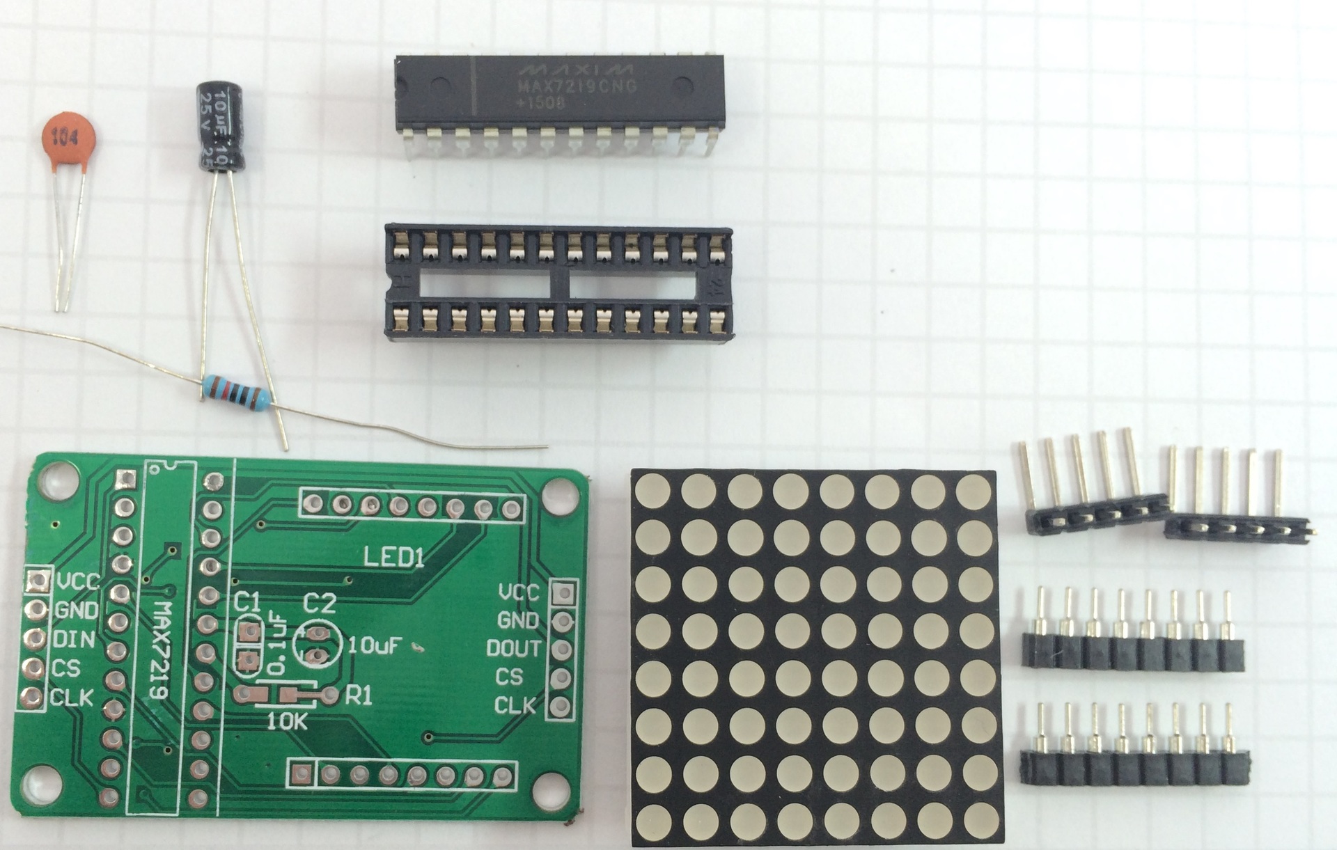
For a long time, an 8 * 8 LED matrix lay in a box complete with a MAX7219 chip for its control, a 10 kOhm resistor, capacitors - ceramic at 100 nF and electrolytic at 10 uF, a wiring board and several connectors. The set is obtained as in the photo . Finally, he gathered his strength and decided to connect it.
For a long time I was looking for how to connect such a kit to raspberry and an example program in C +, but I did not find it, but there are many examples for arduino. It was possible to find only an example of python code and instructions for setting up , which for lack of a better one I used. And in this material I will tell in detail how to connect.
Firstly, it is necessary to assemble this kit on a printed circuit board - everything is simple there, especially after reading the soldering instructions “soldering is simple”.
Check if we have SPI enabled. To do this, enter in the terminal:
You should get something like this:
If nothing is returned,
We check if we have SPI installed in / dev, for this we type in the terminal:
On the screen should receive:
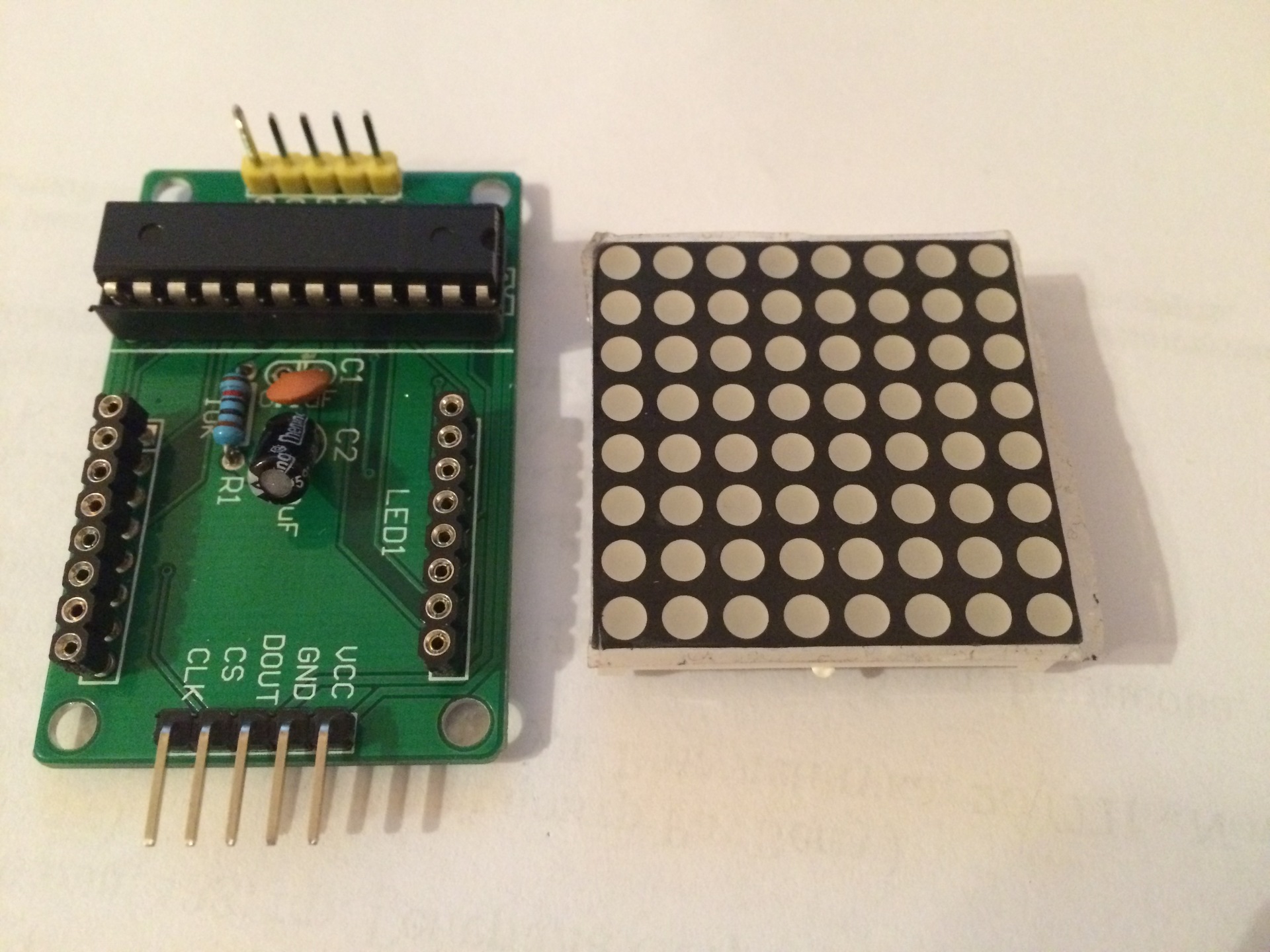
We connect our module to Raspberry:
VCC - to 5V raspberry
GND - to gnd
DIN (data in) - GPIO 10 (SPI MOSI)
CS (chip select) - GPIO 8 (SPI CS0)
CLK (clock) - GPIO 11 (SPI CLK)
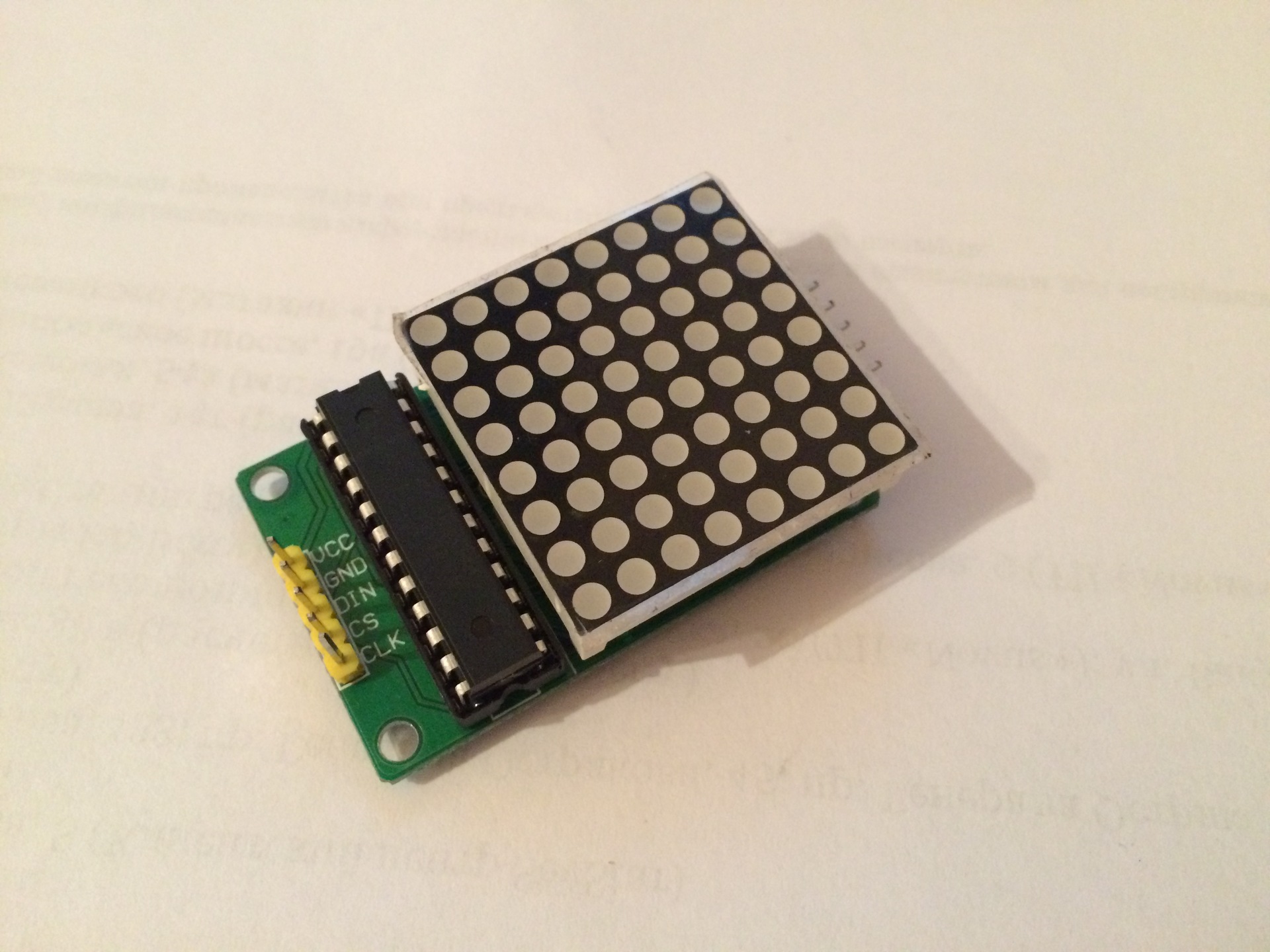
On the other side of the module there are pins with similar designations - they are designed for serial connection of modules.
We install the necessary programs for displaying information on the display.
Download the library to work with the module:
Install the necessary components:
Run the existing example and check the operation of the module:
A running line with the text from the example should appear on the display. The text can be changed, for this we edit the file using the command:
The display text is shown in brackets after the device.show_message command.
An example of a display based on the idea of dev_random :
For a long time I was looking for how to connect such a kit to raspberry and an example program in C +, but I did not find it, but there are many examples for arduino. It was possible to find only an example of python code and instructions for setting up , which for lack of a better one I used. And in this material I will tell in detail how to connect.
Firstly, it is necessary to assemble this kit on a printed circuit board - everything is simple there, especially after reading the soldering instructions “soldering is simple”.
Getting started setting up raspberries
Check if we have SPI enabled. To do this, enter in the terminal:
dmesg | grep spi
You should get something like this:
[    8.581285] spi spi0.0: setting up native-CS0 as GPIO 8
[    8.589797] spi spi0.1: setting up native-CS1 as GPIO 7
If nothing is returned,
then enable SPI so
We go into the Raspberry setup program:
Item 8 Advanced options> A6 SPI> Yes (Would you like the SPI interface enabled?)> OK> Yes (Would you like the SPI kernel module to be loaded by default?)> OK
sudo raspi-config
Item 8 Advanced options> A6 SPI> Yes (Would you like the SPI interface enabled?)> OK> Yes (Would you like the SPI kernel module to be loaded by default?)> OK
We check if we have SPI installed in / dev, for this we type in the terminal:
ls -l /dev/spi*
On the screen should receive:
crw-rw---T 1 root spi 153, 0 Jan  1  1970 /dev/spidev0.0
crw-rw---T 1 root spi 153, 1 Jan  1  1970 /dev/spidev0.1
We connect our module to Raspberry:
VCC - to 5V raspberry
GND - to gnd
DIN (data in) - GPIO 10 (SPI MOSI)
CS (chip select) - GPIO 8 (SPI CS0)
CLK (clock) - GPIO 11 (SPI CLK)
On the other side of the module there are pins with similar designations - they are designed for serial connection of modules.
We install the necessary programs for displaying information on the display.
Download the library to work with the module:
git clone https://github.com/rm-hull/max7219.git
Install the necessary components:
sudo apt-get install python-dev python-pip
sudo pip install spidev
sudo python setup.py install
Run the existing example and check the operation of the module:
sudo python examples/matrix_test.py
A running line with the text from the example should appear on the display. The text can be changed, for this we edit the file using the command:
nano examples/matrix_test.py
The display text is shown in brackets after the device.show_message command.
An example of a display based on the idea of dev_random :