RandomRace.ru - direction finding for a few dollars (continued)

Start there .
And then suddenly I find HC-11 modules on aliexpress. This is a UART extender made from the same STM8S003F3P6 and TI's CC1101 sub-gigahertz digital transceiver. The cost of the module also pleased - $ 3.5- $ 8 along with delivery.
And away we go. Datasheet, scratch turnips, datasheet again, seagull, datasheet, where is my credit card? Tracker, tracker, tracker ... What the hell, how was it delivered to Singapore ??? Contrary to habits, for the first time in my life I did not check the delivery address ... By a strange whim of aliexpress, the package with trial cards went to the address of the hotel where I stayed a year ago and ordered something at the same time. So, in Singapore, a seconded colleague. Can go to the hotel? Can. Alle, is this a hotel? Did you receive a parcel in my name? My colleague will come to you, and ... And, they have already sent back ... Thank you, everything is fine, sorry for bothering ... :-(
There is nothing to do, time is running out, I had to order a test batch again, sourly overpaying for em. , the treasured parcel finally arrived.

Attempt # 2
Electronics, transmitter.
An hour of picking with a tester, and partial reverse engineering is completed. The board made a good impression - the power was filtered, the level converters on the signal outputs are collective farm, but quite working. In principle, everything turned out to be expected - the microcontroller hardware spi (PC5-PC7) looks at the transceiver, UART (PD5, PD6) looks out through level converters, the flashing legs are led out to the test pads from the bottom of the module. Engineering intelligence only reported the subtleties - which leg is assigned to the CS (PD4) signal of the transceiver, and which - to the SET (PC3) input of the entire module. Now the next step is

Thus, the manufacture of the transmitter boils down to soldering a bare LED, a power wire and a standard antenna. In order to protect the wires from damage, and the circuit itself from dampening, sealed transmitters were filled with hot-melt adhesive and drawn into heat shrink.
Firmware, transmitter.
The C1101 chip is controlled by the standard spi protocol by reading and writing registers, there is also a FIFO buffer for packet data exchange. It is recommended that the chip parameters (i.e., the values of these registers) be configured not by the careful look, but using the SmartRF Studio utility downloaded from the TI website. The utility is really good, intuitive, and even allows you to generate source code from a template.

After a series of experiments with the chip, we managed to get it to work at different capacities, in any channel of the LPD range. The next step is the actual structure of the transmitted data. On the one hand, I would like the sound of the lighthouse to be uniquely identified by ear on the radio. On the other hand, it’s foolish not to take advantage of the capabilities of the chip and not convey something useful. On the third hand, all these games with the radio should not put the battery in excess. The chip itself is digital, first transmitting the bit pattern of the preamble, then the synchronizing word, then the data packet and the optional CRC. The transmission format was invented as follows - approximately every 3 seconds, the transmitter transmits a series of pulses of 5 packets. Each packet consists of 2 bit patterns, between them - 3 bytes of payload. This is the number and current transmitter power in dB and the control byte is the power inversion. Modulation is GFSK, bit patterns are 101010 ... and 110110 .... When such a signal passes through the FM receiving path of the radio, the sound is two-tone, approximately 300 and 200 Hz, and is easily recognized against the background of natural and man-made noises. Each packet is transmitted with a different power: -30, -20, -10, 0, 10 dB. As a person with a walkie-talkie approaches the transmitter, more and more packets from the series begin to prevail over noise, and the walkie talkie hears a longer series of signals. Thus, it is possible to very roughly estimate the distance to the lighthouse using the banal LPD walkie-talkie, which, by its FM nature, contradicts working as a direction finder. and is easily recognized against the background of natural and man-made noises. Each packet is transmitted with a different power: -30, -20, -10, 0, 10 dB. As a person with a walkie-talkie approaches the transmitter, more and more packets from the series begin to prevail over noise, and the walkie talkie hears a longer series of signals. Thus, it is possible to very roughly estimate the distance to the lighthouse using the banal LPD walkie-talkie, which, by its FM nature, contradicts working as a direction finder. and is easily recognized against the background of natural and man-made noises. Each packet is transmitted with a different power: -30, -20, -10, 0, 10 dB. As a person with a walkie-talkie approaches the transmitter, more and more packets from the series begin to prevail over noise, and the walkie talkie hears a longer series of signals. Thus, it is possible to very roughly estimate the distance to the lighthouse using the banal LPD walkie-talkie, which, by its FM nature, contradicts working as a direction finder.
Pulses are transmitted every three seconds, the duration of the series is approximately half a second. CC1101 in transmission mode consumes 20 to 30 mA, depending on the transmitted power. Thus, the average consumption of the entire transmitter is about 5 mA. We used different batteries for the transmitters, but spare batteries to cell phones turned out to be the best option in terms of price-capacity ratio. The Nokiev battery at a cost of 250 rubles has a capacity of 1350 mAh, i.e. it is enough for about 11 days of transmitter operation. In order to reduce consumption, the controller after transmitting a series of pulses puts the transceiver in stand-by mode, and it goes into stop mode. To restart the controller, the IWDG watchdog is used, which works from its own generator and can wake a stopped and even deadlocked MK. Deaf freezing cannot be ruled out since the probe, together with the lighthouse, rises to a considerable height, where the temperature can be up to -60С. Unfortunately, in stm8s controllers, the maximum duration of this watchdog is a little more than a second, which is clearly not enough. Therefore, you have to keep in mind the counter of the operation of the watch and transmit a series of pulses once out of three.
Electronics, receiver
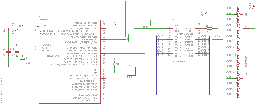
As the receiving node of the receiver-direction finder, the same HC-11 module was taken, but, of course, with a different firmware. He has not enough output legs to start both the LED driver and the sound, but I already had an unsoldered experimental direction finder of the 1+ generation, on an industrial printed circuit board, already with a mic, driver and indicator.

As a result, the direction finder became "dual core." One STMka as part of the transceiver receives a signal, the result is transmitted via the UART interface to a second STMka, and that, in turn, serves the indicator and blows into the piezo emitter. The antenna remained unchanged, the old receiver tore off the board and tore off the antenna track. The new module was soldered to the feet of the controller and antenna and glued to the board on a 2-sided gallop.
Both the HC-11 module and the information receiving MK work fine with a supply voltage of 3.0..5.5V, so you can power it all from a single-cell lithium (again telephone) battery, and the voltage regulator has left the circuit.
The final scheme looked something like this:
As always, time was running out for me, and the case for the electronic part of the receiver had to be made at the last moment from anything. It turned out to be a disgusting (at first glance) “jewelry box” in the “Everything for 37 rubles” store. The rushechki and the mirror with which it was equipped made me cry out blood, but they very quickly went to the trash. The rest of the box is a miracle how good it is - translucent white plastic hides the "implementation details", but allows you to see the luminous numbers of the indicator perfectly. The size is ideal, just the board + battery + switch, and even the lid with a latch.

Receiver, firmware.
As already mentioned, the receiver turned out to be dual-core, and there are also two firmware in it. The flipped hc-11 module constantly reads the RSSI value and checks to see if the data packet identified by the transceiver and containing three payload bytes corresponding to the transmission format has arrived (see above). He reports all of his observations via the UART interface to “superiors.” The second MK listens to the data coming from the first, recounts the RSSI values in the next "parrots", forms the numbers on the indicator and squeaks. If a data packet from the transmitter is not detected, then the read RSSI is used as the initial value, and if the packet is detected, then the sum of the RSSI read and the transmitter power from the received packet are used. The priority, of course, is the data that is received from the transmitter.
As in the first version of the receiver, the receiver reads the calculated value of the "approximation coefficient" and displays it on the indicator. The indicator alternately displays either a coefficient or a transmitter number. If the transmitter number is not accepted, then dashes are shown instead of the number. The sound signaling also depends on the nature of the received signal - the frequency of repetition of “beeps” depends on whether the received signal is an recognized signal of the transmitter - in this case, “beeps” follow twice as often. The rigidity of the “beeps”, as before, is an indicator of rapprochement.
Field trials.

Unfortunately, no full-scale preliminary tests were carried out, simply for lack of time. Everything was tested directly "in the field." However, some tests were carried out in the city. Along with its transmitter, one of the most affordable LPD walkie-talkies was used for testing - Midland LTX-325.
Town
The maximum audibility range of the transmitter in a straight line to the walkie-talkie is 600m with the noise cutter turned off, 280 - with it turned on. Naturally, in the city the 433MHz band is quite noisy with car alarms, walkie-talkies of builders and security guards. The receiver constantly shows 15 "parrots".
In the country
Outside of civilization, the background interference signal is slightly lower, usually 12-13 units. Usually in a forest a beacon can be heard using a walkie-talkie from a distance of about 300 meters. One competitor claimed to have heard the lighthouse from a distance of 1,500 meters through the Yaesu portable walkie-talkie. Once I heard a beacon of a launched probe for several minutes. Given the wind speed that day (approximately 50 km / h), the hearing distance was of the order of several kilometers. The direction finder usually tracks the station from a slightly shorter distance than the walkie-talkie, in the forest it is 150-300 meters. The directivity of the antenna allows you to generally catch where the beacon is. The direction finder indicator shows about 12-15 units at the edge of the reception area, approximately 80-90 near the lighthouse. In some cases, this figure was around 60.
results
We used this equipment both for randomrace.ru competitions and for other launches. The system as a whole has shown its reliability and usefulness at a very moderate cost and complexity. There were times when direction finding relieved us of the long and boring search for a fallen probe in a swampy forest. In principle, the whole project can be performed by any amateur.
Money
Each transmitter costs about $ 10 - a module with an antenna ($ 3.5) + battery (~ $ 5) + power tail + shrink + hotmelt.
The cost of the receiver is more difficult to calculate, as they were not mass-produced, and quite a lot of money and effort was spent on experiments.
Links:
The first part: geektimes.ru/post/270168
Approximately the same in English: www.randomrace.ru/2015/gsbc/preparation/transmitter/eng
RandomRace: randomrace.ru (the nearest competitions: www.randomrace.ru/2016/ spring )
Source code for all firmware: sourceforge.net/projects/randomracebeacon
GBSC: www.balloonchallenge.org/teams/15