LED cube + snake
Foreword
In this article, we (since the article was written and made by a project of 2 people) will tell you how we breathed life into the old game, forgotten by everyone.

Training
Let's start with the cube. We did not come up with a “bicycle” and decided to look for ready-made solutions. The article was based on an article by a Norwegian author, although some changes were made, which, it seems to me, were beneficial.
Create your own LED cube
Having discussed some points, it was decided to make a 8x8x8 cube. We managed to buy 1000 LEDs in bulk at a good price, just what you need, though these were not really suitable LEDs. Visually, blue LEDs with a matte lens would look better, the glow is not so bright and more uniform. There is another problem with transparent LEDs; the lower layer highlights the upper ones. However, despite all this, the LEDs must be bright enough to make the image clear. For more cube transparency, it is better to take small LEDs, for example, 3 mm. Another point when choosing LEDs is the length of the legs. We will make the cube frame from the legs of the LEDs, so they should not be smaller than the size of the cage.
Another important point when building a cube is its size. We make the frame using the legs of the LED, although there are ways where metal rods or wire are used. The length of the cathodes of our LEDs turned out to be approximately 25 mm, so we chose a cell size of 20 mm, and decided to use the rest for soldering, so the cube would be stronger. This is just a slight difference from the design of the author of the article above.
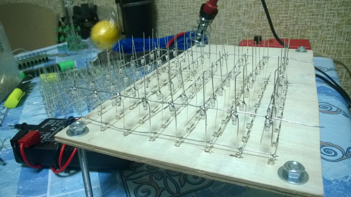
The next step is to create a layout for soldering cube layers, this will help to facilitate soldering and the cube will be more even. The layout is very simple, I took a piece of plywood, drew it according to the size of my cube and drilled holes at the intersection of the lines in size of the LEDs.
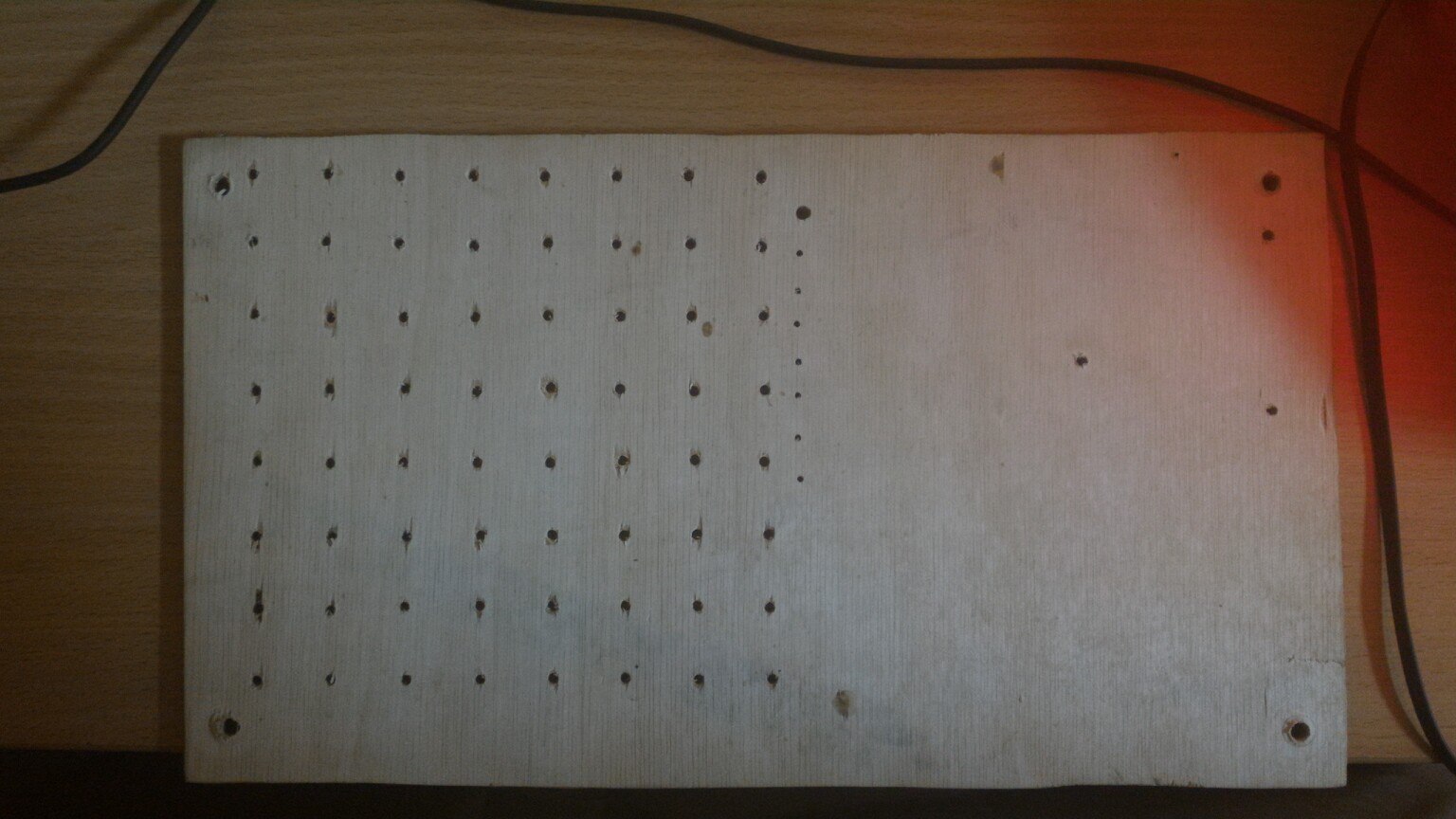
Soldering several layers, I realized that this design is not enough legs, which served as long bolts.
Before you start soldering the cube, I advise you to prepare everything. From personal experience I can say that it is much more convenient to do this together, because there are really not enough hands, one person applies cathodes, and the second feeds solder and solders. You need to do this quickly, the LEDs are small and afraid of overheating. Also in different manuals they say check each LED before soldering. I don’t see the point, spend a lot of time on an essentially meaningless operation. We bought new LEDs and they all turned out to be working. But when you soldered the layer, it’s already worth it to check everything well, because soldering the LED from the center is an unpleasant task, it was checked by personal experience.
So, let's proceed directly to the soldering. I can’t say that this is the surest way, but we did it that way. To begin with, we have all the LEDs in our layout, it is advisable to install them smoothly, then there will be no way to fix something.
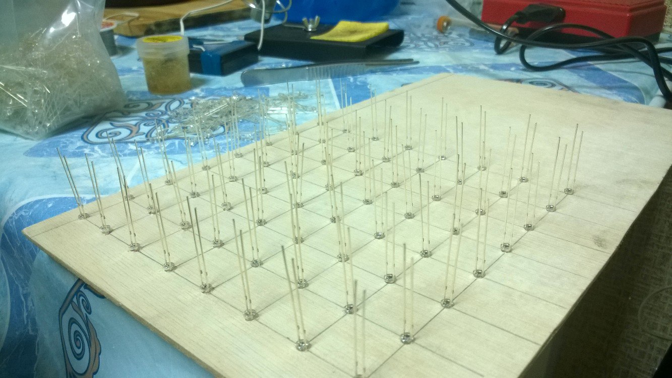
Then we bend the cathodes so that they overlap each other. When everything is ready, you can start to solder, but you should remember about a possible overheating, and if the soldering fails, do not rush to solder, it is better to let the LED cool down.
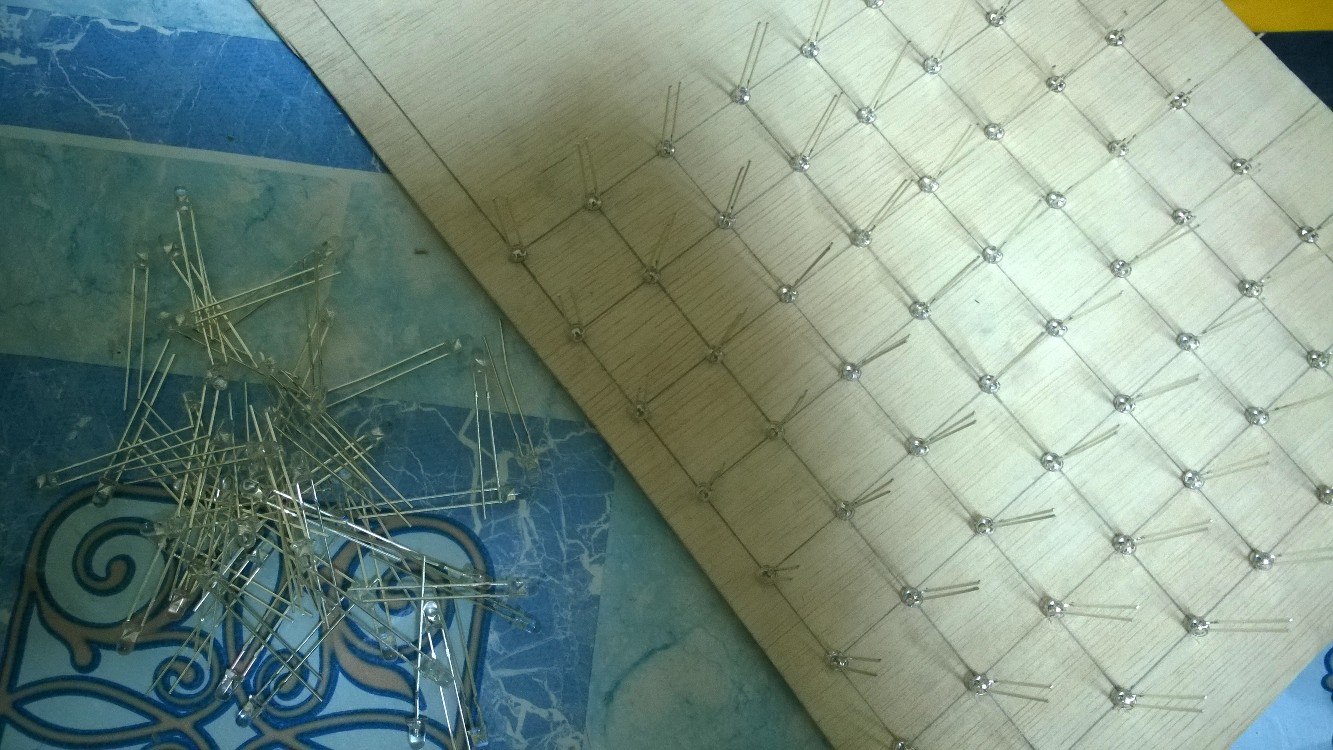
Soldering all the LEDs, we get 8 strips of 8 LEDs. In order to turn it all into one layer, we used ordinary aluminum wire, which was previously straightened. We decided to use only 2 of these “rods”, so as not to complicate the design, by the way it turned out to be quite strong.
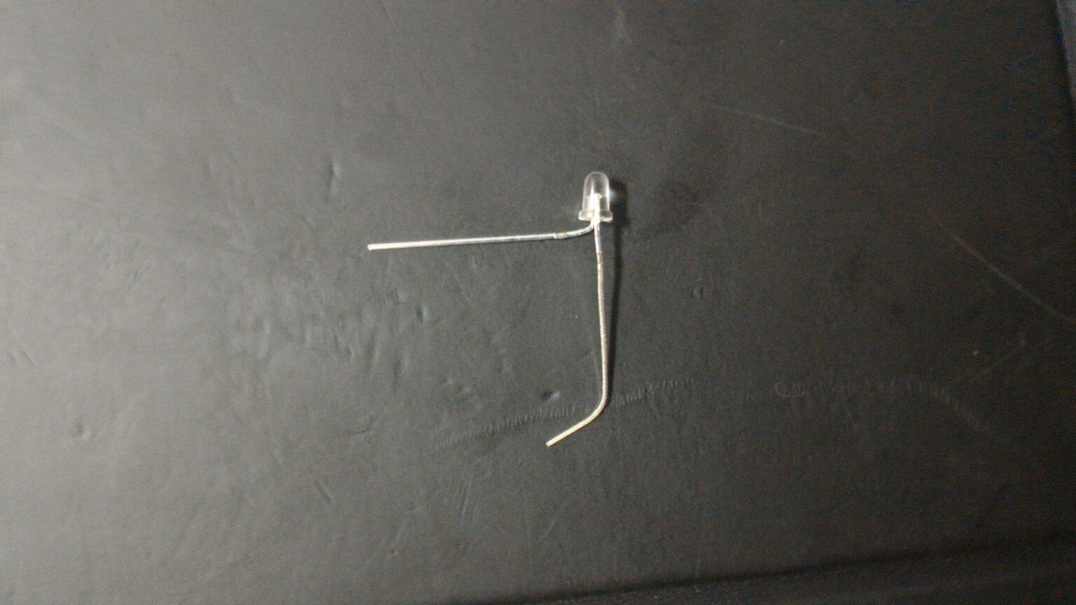
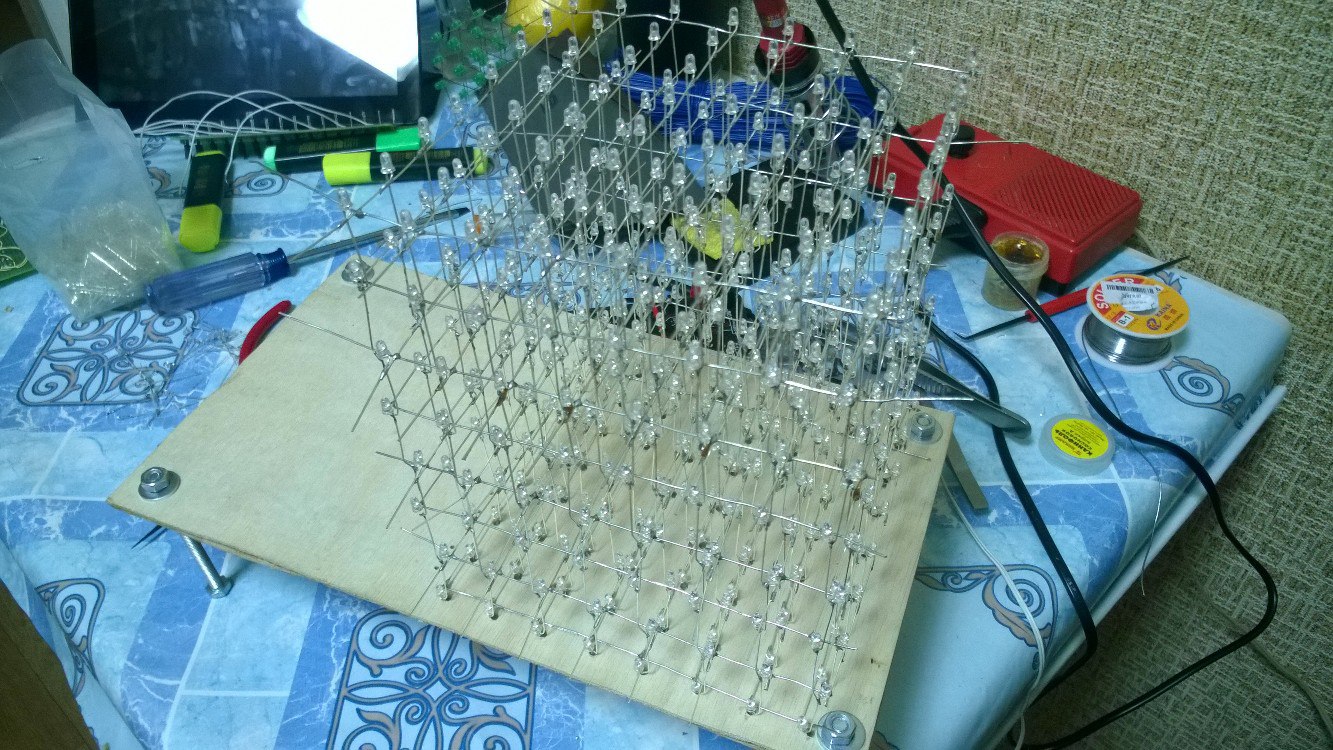
Soldering the last layer does not need to get it because then you have to insert it back. Now that we have all 8 layers, we need to somehow combine them into one cube. To make the cube more or less even, I had to bend the anodes as shown in the figure, now it goes around the LED, and can be neatly soldered.
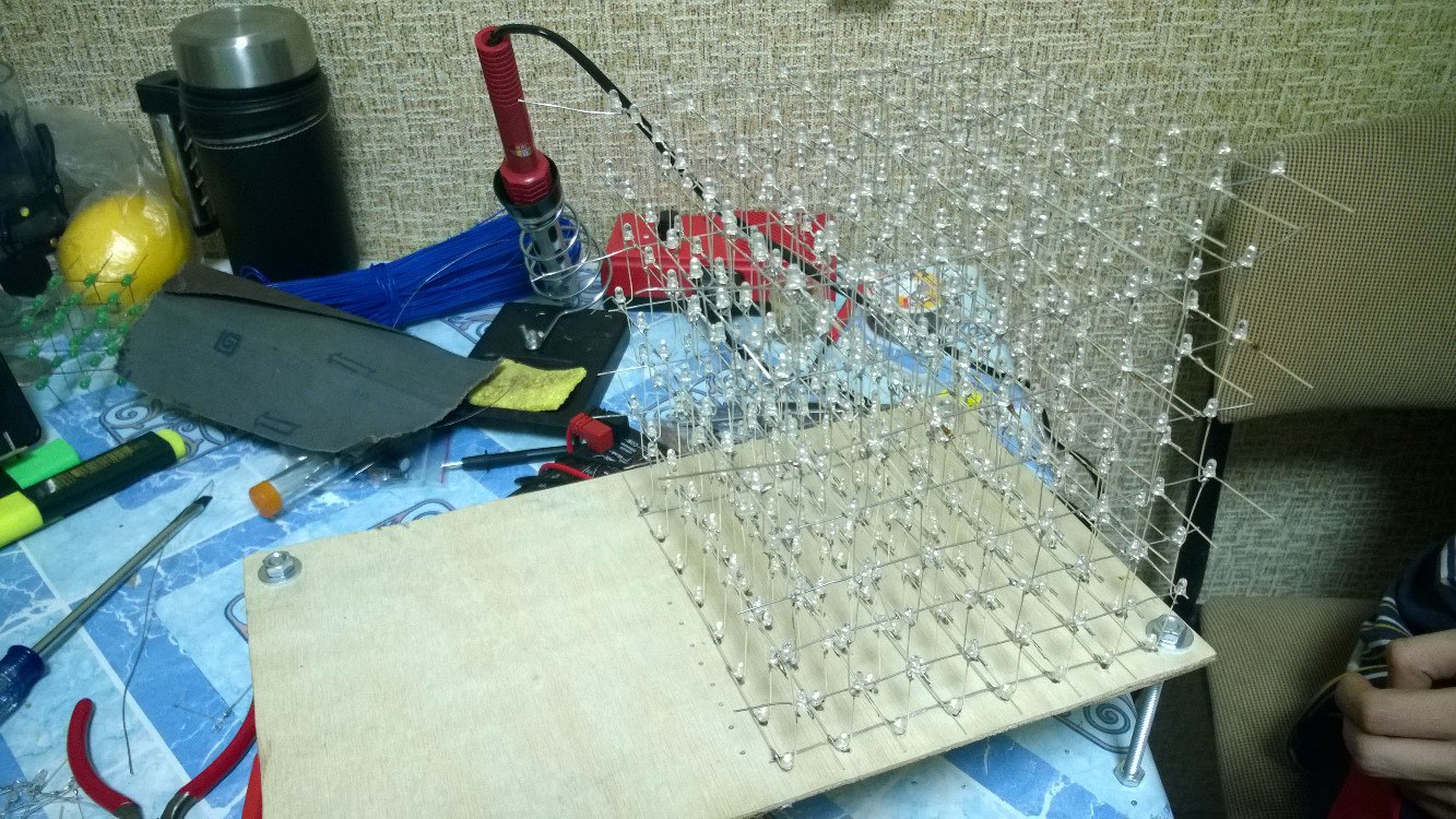
We solder the cube from the top layer to the very bottom, while constantly checking the operation of the LEDs, it is better not to be lazy, because then it will be more difficult to fix the error. It is better to set the height between the layers with the help of some templates, the author of the above article used ordinary crowns. We did not have anything suitable, but there were two of us, so we decided to set everything up manually. It turned out quite smoothly, but not perfect.
Having done all these actions, you will get the LED cube you collected and a few burnt fingers, but this already depends on your accuracy.
Circuit design
To implement our ideas, we needed some kind of microcontroller. We decided to stay on the Arduino Leonardo microcontroller. We did not want to bother about programmers and the necessary software, just we do not need a powerful processor for our tasks. Having the finished device, we realized that it was possible to use Nano, but this is not so critical. To control the cube, we decided to use a phone connected to the Arduino via Bluetooth, in our case the HC-05 is used, but you can use any other.
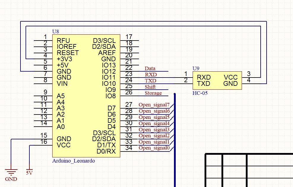
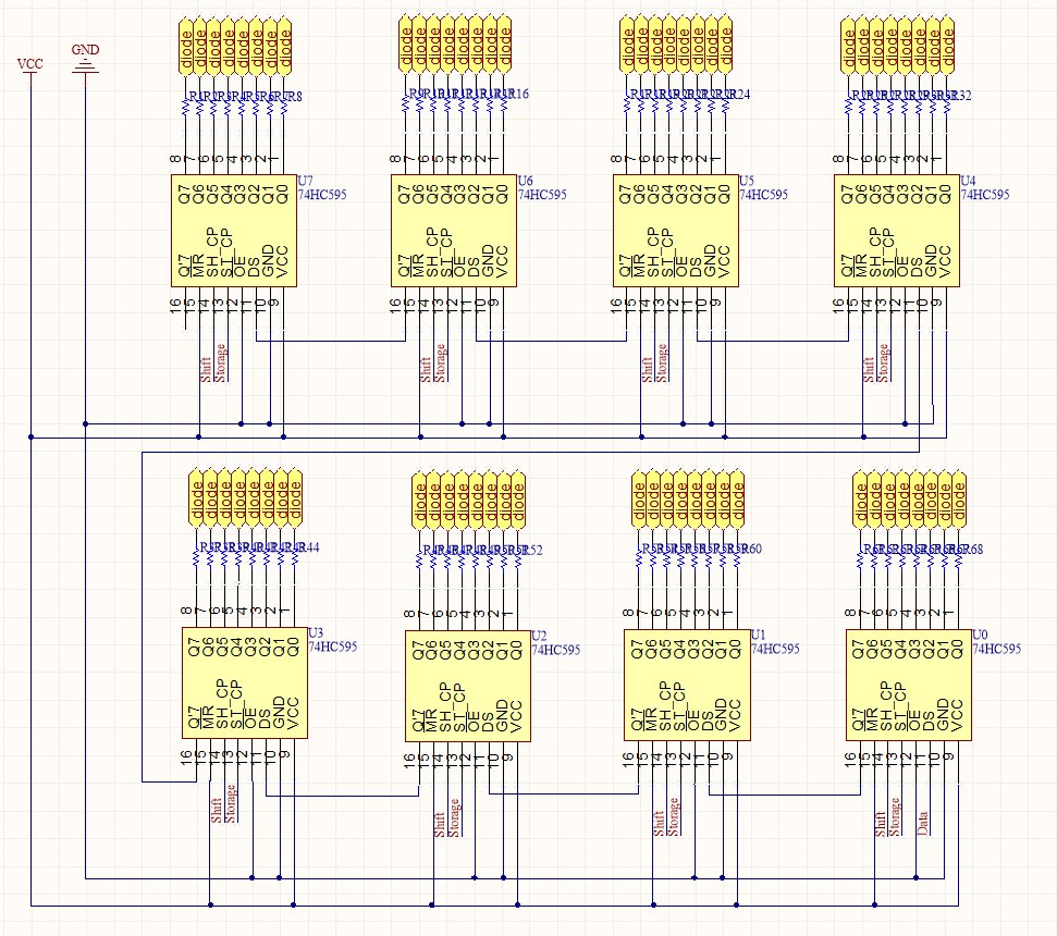
But what’s really important is the number of microcontroller pins, because we got 64 anode and 8 cathode pins, but we’ll talk about connecting them later. We decided to expand the IO ports using shift registers, in our case these are TI 74HC595 registers in the DIP package to solder the sockets to the board, and insert the microcircuits into them. You can read more about these registers in the datasheet, I’ll just say that we used everything except the register reset signal, we applied a unit to it, because it is inverse, and we turned the output enable input to ground, it is also inverse and we always wanted to receive data from registers. You could also use sequential registers, but then you would have to put a decoder to select which register to write information to.
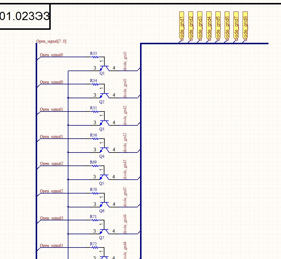
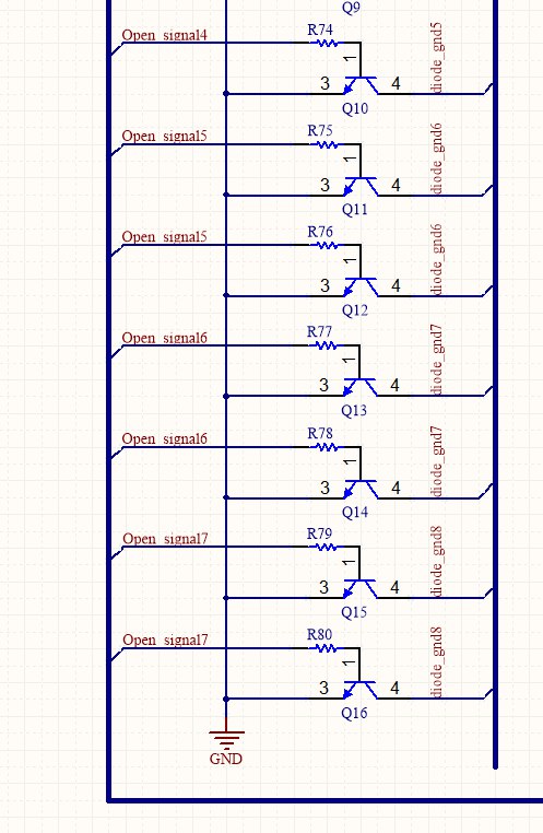
In order to close the circuit to ground, choosing the level that we want to ignite, we need transistor switches, well, or just transistors. We used ordinary NPN type low-power bipolar transistors connected in parallel in 2. Not sure if that makes sense, but it’s kind of like the current flows better. The base through a pull-up resistor of 100 Ohms is connected to the microcontroller, which will open our transistors. The cube layers are connected to the collector, and the emitters are connected to the ground.
Putting the cube together
They could not find anything better to supply the cube than the power supply from the tablet, whose parameters are 5 V and 2 A. Maybe this is not enough, but the cube glows quite brightly. In order not to burn the LEDs, all the anode terminals are connected to the registers through a current-limiting resistor. According to my calculations, they should have been approximately 40 Ohms, but I didn’t have such, so I used 100 Ohms.
We placed all this on 2 small printed circuit boards. They didn’t intentionally poison anything due to the lack of practice, they simply connected everything with ordinary conductors. The registers with the anodes of the cube were connected using the cables that we took out from the old computer. It’s easier to navigate the wires.
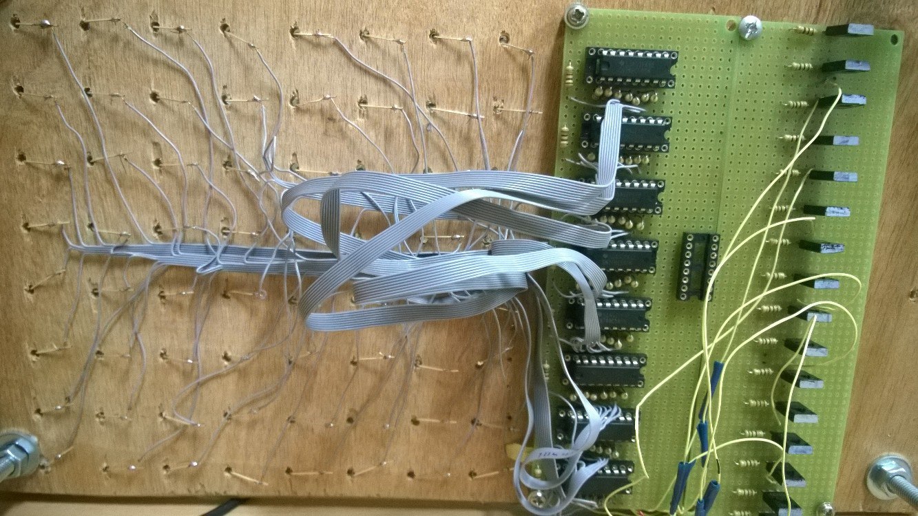
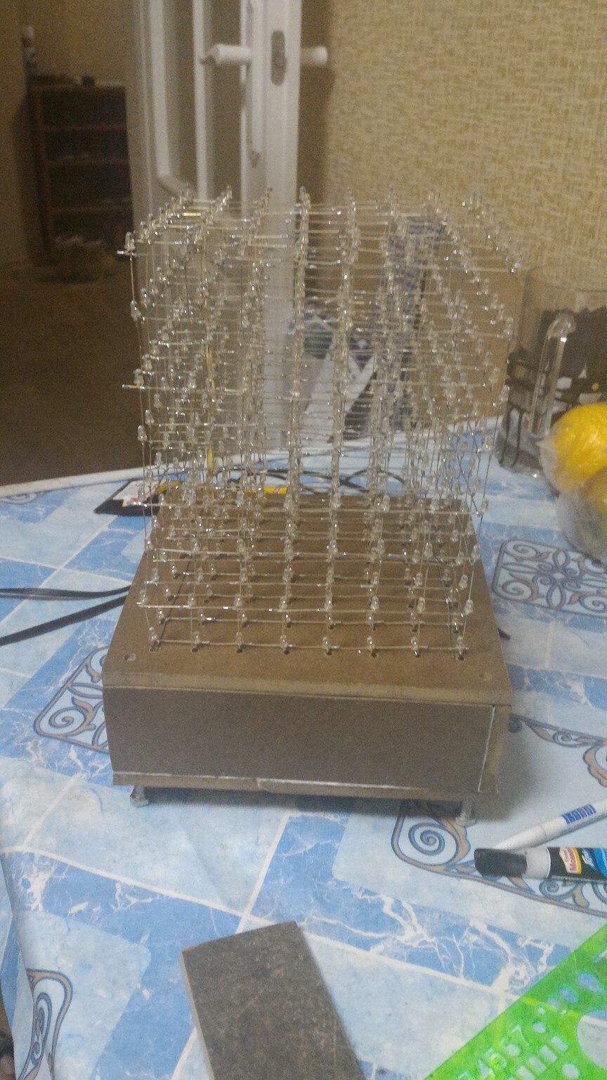
They decided to assemble the prototype on the layout used for soldering.

Having debugged everything and correcting the mistakes made, we made the body of the laminate that we have, it turned out to be good because it did not have to be painted. Here is the end result:
Let there be light!
There is a cube, it remains to make it glow. Next, various modes (modes) of the cube will be described, for switching which bluetooth + Android was used. The phone application was written using Cordova. The application code will not be described here, but the link to the repository is presented in the conclusion.
Cube algorithm
Due to the fact that we do not have access to all the LEDs at once, we cannot light them all at once. Instead, we need to light them in layers.
The algorithm is as follows:
- The current layer is 0.
- Register the mask for the current layer
- Close the transistor for the previous layer. If the current layer is zero, then the previous layer is the 7th layer
- We click values into registers. Value appear on the outputs of the registers
- Open the transistor for the current layer. Hooray, one layer glows!
- Current layer ++. goto: 2
In total, this algorithm repeats quite quickly, which gives us the illusion that all the LEDs are lit at the same time (but we know that this is not so). Masks are stored in a 64x8 byte array.
Writing mods
These modes did not appear in the order in which they will be presented here, so please do not punish them by numbering in the code. Let's start with the simplest: light up all the LEDs.
Light the cube
void Mode_2_Init() {
	for (byte z = 0; z < CUBE_EDGE_SIZE; z++) {
		for (byte y = 0; y < CUBE_EDGE_SIZE; y++) {
			for (byte x = 0; x < CUBE_EDGE_SIZE; x++) {
				cube->data[z * CUBE_LEVEL_SIZE + y * CUBE_EDGE_SIZE + x] = 1;
			}
		}
	}
}
The "sticky" mod
Idea: only two layers of zero and seventh burn, and they are inverse with respect to each other (the LED in position X is lit only on one of the layers). The position is randomly selected (for some reason everyone is trying to find an algorithm for selecting the position), and the LED in this position “crawls” to the upper layer if it was lit on the lower layer, and accordingly to the lower if it was lit on the upper.
Sticky code
void Mode_0() {
	byte positionToMove = random(CUBE_LEVEL_SIZE);
	byte fromLevel = cube->data[positionToMove] == 1 ? 0 : 7;
	bool top = fromLevel == 0;
	cube->ShowDataXTimes(5);
	while (true) {
		byte toLevel = top ? fromLevel + 1 : fromLevel - 1;
		if (toLevel >= CUBE_EDGE_SIZE || toLevel < 0) break;
		cube->data[fromLevel * CUBE_LEVEL_SIZE + positionToMove] = 0;
		cube->data[toLevel * CUBE_LEVEL_SIZE + positionToMove] = 1;
		cube->ShowDataXTimes(2);
		fromLevel = toLevel;
	}
}
void Mode_0_Init() {
	cube->Clear();
	for (byte i = 0; i < CUBE_LEVEL_SIZE; i++) {
		byte value = random(0, 2);  // max - 1
		cube->data[i] = value;  //first level
		cube->data[i + (CUBE_EDGE_SIZE - 1) * CUBE_LEVEL_SIZE] = !value;  //last level
	}
}
What it looks like in life:
“Another sticky mod”
This mod is similar to the previous one, except that the layer is not burning, but the face, and the lights from this face, one by one move to the opposite, and then back.
Another sticky code
void Mode_3_Init() {
	cube->Clear();
	positions->clear();
	new_positions->clear();
	mode_3_direction = NORMAL;
	for (short y = 0; y < CUBE_LEVEL_SIZE * CUBE_EDGE_SIZE; y += CUBE_LEVEL_SIZE) {
		for (byte x = 0; x < CUBE_EDGE_SIZE; x++) {
			cube->data[x + y] = 1;
			positions->push_back(x + y);
		}
	}
}
void Mode_3() {
	if (positions->size() == 0) {
		delete positions;
		positions = new_positions;
		new_positions = new SimpleList();
		mode_3_direction = mode_3_direction == NORMAL ? INVERSE : NORMAL;
	}
	byte item = random(0, positions->size());
	short position = *((*positions)[item]);
	positions->erase(positions->begin() + item);
	byte i = 1;
	while(i++ < CUBE_EDGE_SIZE ) {
		cube->data[position] = 0;
		if(mode_3_direction == NORMAL) position += CUBE_EDGE_SIZE;
		else position -= CUBE_EDGE_SIZE;
		cube->data[position] = 1;
		cube->ShowDataXTimes(1);
	}
	new_positions->push_back(position);
}
Cube inside a cube
Idea: light up the LEDs inside the cube in the form of faces of the cube with sizes from 1 to 8 LEDs and vice versa.
Cube inside a cube
void Mode_1() {
	cube->Clear();
	for (byte cube_size = 0; cube_size < CUBE_EDGE_SIZE; cube_size++) {
		for (byte level = 0; level <= cube_size; level++) {
			for (byte x = 0; x <= cube_size; x++) {
				for (byte y = 0; y <= cube_size; y ++) {
					cube->data[level * CUBE_LEVEL_SIZE + y * CUBE_EDGE_SIZE + x] =
						(y % cube_size == 0 || x % cube_size == 0)
						&& level % cube_size == 0 ||
						(y % cube_size == 0) && (x % cube_size == 0) ? 1 : 0;
				}
			}
		}
		cube->ShowDataXTimes(5);
	}
	for (byte cube_size = CUBE_EDGE_SIZE - 1; cube_size > 0; cube_size--) {
		for (byte level = 0; level <= cube_size; level++) {
			for (byte x = 0; x <= cube_size; x++) {
				for (byte y = 0; y <= cube_size; y++) {
					cube->data[level * CUBE_LEVEL_SIZE + (CUBE_EDGE_SIZE - 1 - y) * CUBE_EDGE_SIZE + (CUBE_EDGE_SIZE - 1 - x)] =
						(((y % (cube_size - 1) == 0 || x % (cube_size - 1) == 0) && (level % (cube_size - 1) == 0))
						|| ((y % (cube_size - 1) == 0) && (x % (cube_size - 1) == 0) && level % cube_size != 0))
						&& x < (cube_size) && y < (cube_size) ? 1 : 0;
				}
			}
		}
		cube->ShowDataXTimes(5);
	}
}
What does it look like:
And finally the snake
Of the features of the implementation of the snake, it is worth noting that there are no restrictions on the field, and accordingly leaving the cube on the one hand, you appear on the other. You can only lose if you bump into yourself (in truth, you can't win).
It is also worth separately telling about management:
In the case of a two-dimensional implementation of this game, there are no issues with management: four buttons and everything is obvious. In the case of a three-dimensional implementation, several control options arise:
1.6 buttons. With this option, the button has its own direction of movement: for the up and down buttons, everything is obvious, and the rest of the buttons can be “tied” to the cardinal points, when you press the “left” button, the motion vector always changes “west”, etc. With this option, situations arise when the snake moves “east” and we click “west”. Because the snake cannot turn 180 degrees; you have to handle such cases separately.
2.4 buttons (Up Down Left Right). The actions of these buttons are similar to those in a two-dimensional implementation, except that all changes are taken relative to the current direction of the motion vector. Let me explain by example: when moving in the horizontal plane, by pressing the “Up” button, we go to the vertical plane. When moving in a vertical plane by pressing “Up”, we move on to moving in a horizontal plane against the direction of the X axis, for “Down” - in the direction of the X axis, etc.
Of course, both options have a right to exist (it would be interesting to know other management options). For our project, we chose the second.
Direction Code
void Snake::ApplyUp() {
	switch (direction) {
	case X:
	case Y:
		direction = Z;
		directionType = NORMAL;
		break;
	case Z:
		direction = X;
		directionType = INVERSE;
	}
}
void Snake::ApplyDown() {
	switch (direction) {
	case X:
	case Y:
		direction = Z;
		directionType = INVERSE;
		break;
	case Z:
		direction = X;
		directionType = NORMAL;
	}
}
void Snake::ApplyLeft() {
	switch (direction) {
	case X:
		direction = Y;
		directionType = directionType == NORMAL ? INVERSE : NORMAL;
		break;
	case Y:
		direction = X;
		directionType = directionType;
		break;
	case Z:
		direction = Y;
		directionType = NORMAL;
	}
}
void Snake::ApplyRight() {
	switch (direction) {
	case X:
		direction = Y;
		directionType = directionType;
		break;
	case Y:
		direction = X;
		directionType = directionType == NORMAL ? INVERSE : NORMAL;
		break;
	case Z:
		direction = Y;
		directionType = INVERSE;
	}
}
void Snake::ChangeDirection(KEY key) {
	switch(key) {
	case UP:
		ApplyUp();
		break;
	case LEFT:
		ApplyLeft();
		break;
	case RIGHT:
		ApplyRight();
		break;
	case DOWN:
		ApplyDown();
		break;
	}
}
The result of the program:
Links to the source code of the cube firmware and application for the phone:
application
firmware
Result
As a result, we got a primitive console and a kind of lamp, with the possibility of dynamic lighting. In the future we plan to develop a printed circuit board and improve the firmware. It is also possible to add additional modules.