Do-it-yourself tabletop robotic arm plexiglass manipulator on servo drives or uArm reverse engineering
Hello Giktayms!
I want to share with you the results of reverse engineering uArm - a simple plexiglass desktop manipulator on servos.
The uArm project from uFactory raised funds on kickstarter more than two years ago. From the very beginning they said that it would be an open project, but right after the end of the company they were in no hurry to upload the source code. I just wanted to cut Plexiglas according to their drawings and that’s all, but since there were no source codes and was not foreseen in the foreseeable future, I began to repeat the design from the photographs.
Now my robo-hand looks like this:
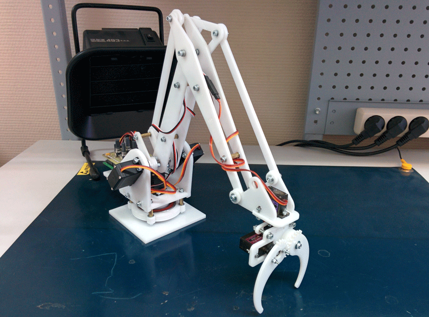
Working slowly for two years, I managed to make four versions and got a lot of experience. Description, project history and all project files you can find under the cut.
Starting to work on the drawings, I wanted to not just repeat uArm, but to improve it. It seemed to me that in my conditions it is completely possible to do without bearings. I also did not like the fact that the electronics rotate with the entire manipulator and I wanted to simplify the design of the lower part of the hinge. Plus, I started drawing it immediately a little less.
With these input parameters, I drew the first version. Unfortunately, I did not have photos of that version of the manipulator (which was made in yellow). The mistakes in it were simply epic. Firstly, it was almost impossible to assemble. As a rule, the mechanics that I drew before the manipulator were quite simple, and I did not have to think about the assembly process. But still, I collected it and tried to run it, And my hand hardly moved! All the details revolved around the screws and, if I tightened them so that there were fewer backlashes, she could not move. If weakened so that she could move, incredible backlashes appeared. As a result, the concept did not live even three days. And he began work on the second version of the manipulator.
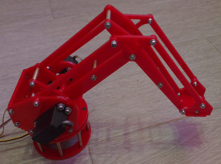
Red was already quite fit for work. He normally assembled and could move with lubrication. On it, I was able to test the software, but still the lack of bearings and heavy losses on different rods made it very weak.
Then I gave up work on the project for a while, but soon decided to bring it to mind. I decided to use more powerful and popular servos, increase the size and add bearings. And I decided that I would not try to do everything perfectly right away. I sketched the blueprints without drawing beautiful mates and ordered cutting from transparent plexiglass. On the resulting manipulator, I was able to debug the assembly process, identified places that needed additional strengthening, and learned how to use bearings.
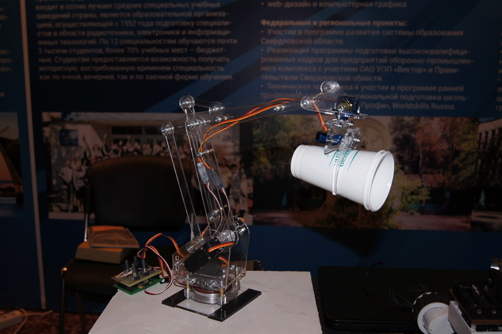
After I played enough with a transparent manipulator, I sat down at the drawings of the final white version. So, now all the mechanics are completely debugged, suits me and is ready to declare that I don’t want to change anything else in this design:
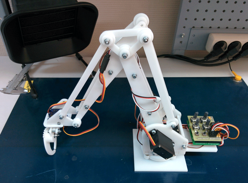
It depresses me that I could not bring anything fundamentally new to the uArm project. By the time I started drawing the final version, they had already rolled out 3D models on GrabCad. As a result, I only simplified the claw a little, prepared the files in a convenient format, and applied very simple and standard components.
Before uArm, desktop manipulators of this class looked rather dull. They either did not have electronics at all, either had any control with resistors, or had their own proprietary software. Secondly, they usually did not have a system of parallel joints and the grip itself changed its position during operation. If you collect all the advantages of my manipulator, you get a fairly long list:
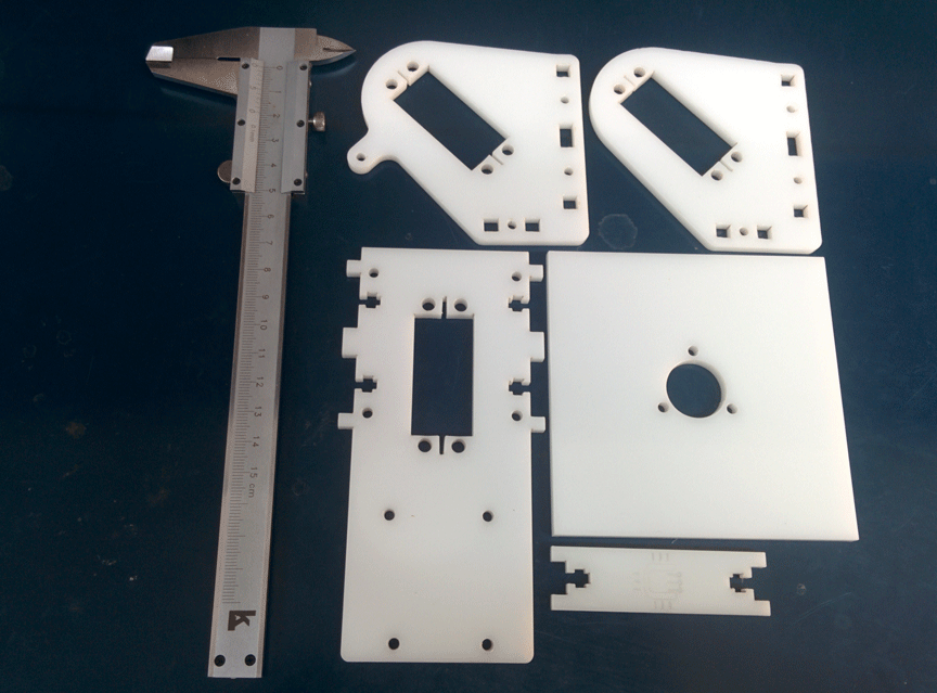
For assembly, it is necessary to cut parts from plexiglas 5mm thick:
... and 3mm:
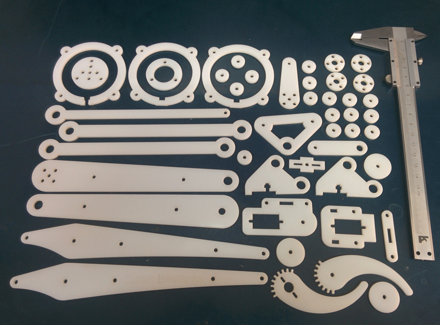
I took about $ 10 for cutting all these parts.
The base is mounted on a large bearing:
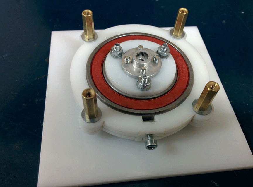
It was especially difficult to think over the base in terms of the assembly process, but I spied on uArm engineers. Rocking chairs sit on a pin with a diameter of 6mm. It should be noted that my elbow traction is held on the U-shaped holder, and uFactory on the L-shaped holder. It's hard to explain what the difference is, but I think I did better.
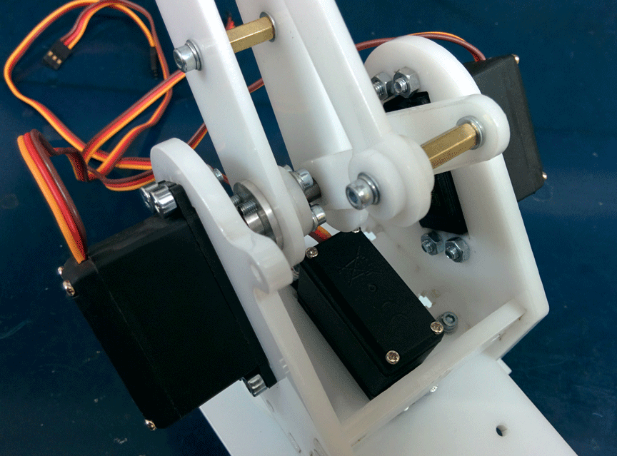
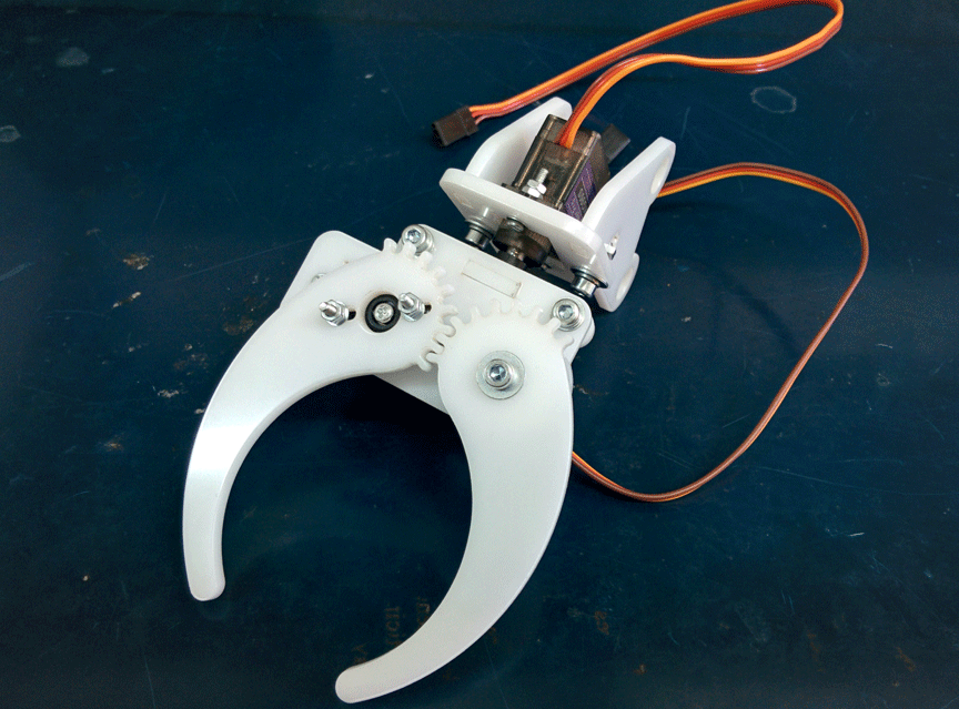
Capture is collected separately. It can rotate around its axis. The claw itself sits directly on the engine shaft:
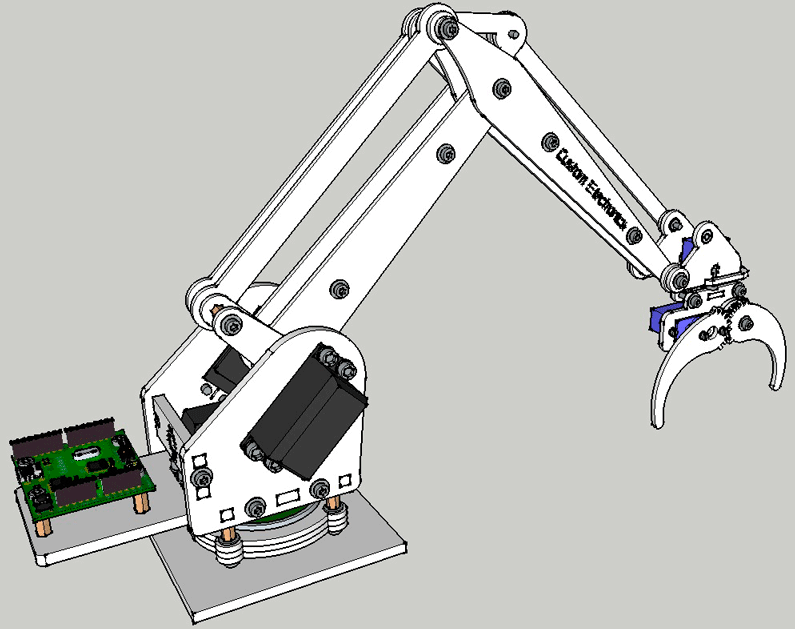
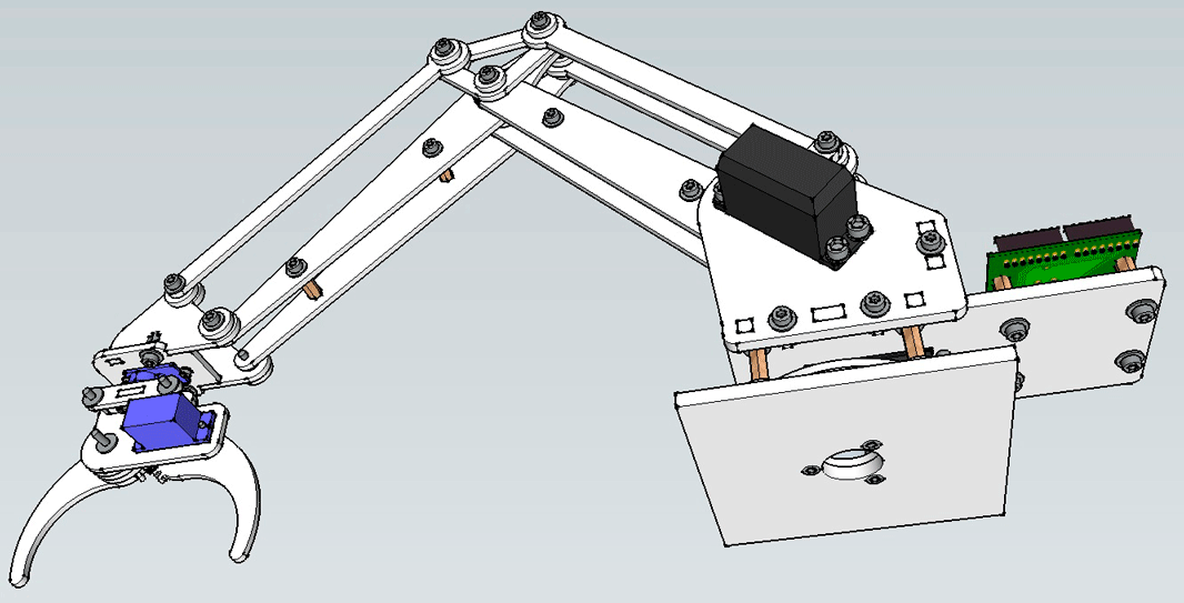
At the end of the article, I will give a link to super-detailed assembly instructions in photographs. In a couple of hours you can confidently twist it all, if everything you need is at hand. I also prepared a 3D model in the free SketchUp program. It can be downloaded, twisted and see what and how assembled.
To make your hand work it’s enough just to connect five servos to the Arduino and apply power to them from a good source. UArm used some feedback engines. I installed three conventional MG995 engines and two small metal gear motors for grip control.
Here my story is closely intertwined with previous projects. For some time now I started teaching Arduino programming and for these purposes I even prepared my Arduino-compatible board . On the other hand, one day I got the opportunity to cheaply manufacture boards (which I also wrote about) As a result, all this ended up using my own Arduino-compatible board and a specialized shield to control the manipulator.
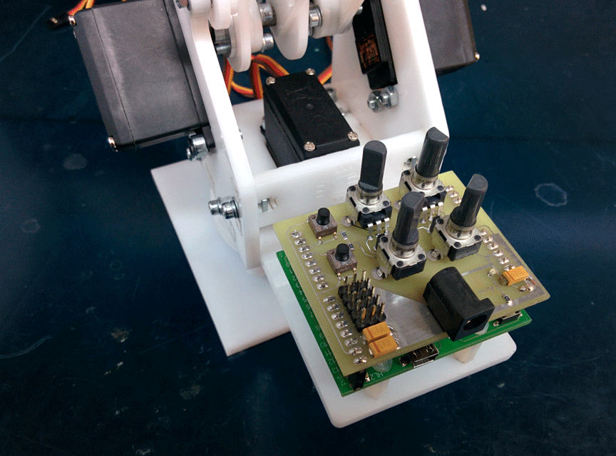
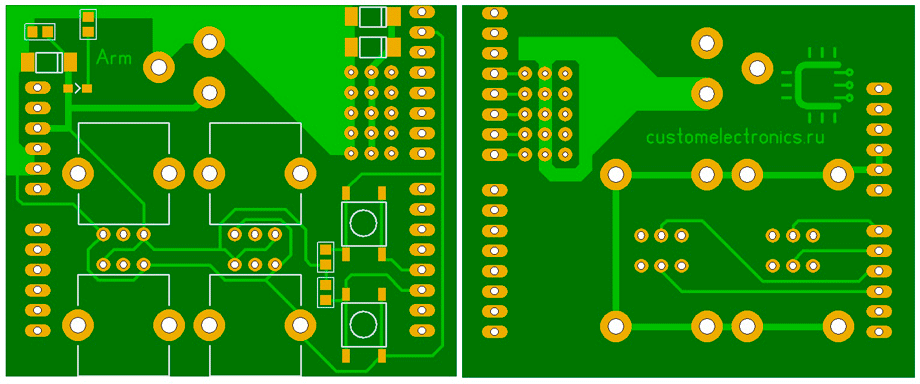
This shield is actually very simple. It has four variable resistors, two buttons, five connectors for the servo drive and a power connector. This is very convenient in terms of debugging. You can load a test sketch and record some kind of macro to control or something like that. I will also give a link to download the board file at the end of the article, but it is prepared for manufacturing with metallization of holes, so it is not suitable for home production.
The most interesting thing is the control of the manipulator from the computer. UArm has a convenient application for manipulator control and a protocol for working with it. The computer sends 11 bytes to the COM port. The first of them is always 0xFF, the second is 0xAA and some of the remaining are signals for servos. Further, these data are normalized and given to the engines for testing. My servos are connected to digital inputs / outputs 9-12, but this can easily be changed.
The terminal program from uArm allows you to change five parameters when controlling the mouse. When the mouse moves on the surface, the position of the manipulator in the XY plane changes. Wheel rotation - change in height. LMB / RMB - squeeze / unclench a claw. RMB + wheel - capture rotation. It is actually very convenient. If desired, you can write any terminal software that will communicate with the manipulator using the same protocol.
I will not bring sketches here - you can download them at the end of the article.
And finally, the video of the manipulator itself. It shows the control of a mouse, resistors and a pre-recorded program.
Files for cutting plexiglass, 3D models, a purchase list, board drawings and software can be downloaded at the end of my main article .
Detailed assembly instructions in photos (carefully, traffic).
I want to share with you the results of reverse engineering uArm - a simple plexiglass desktop manipulator on servos.
The uArm project from uFactory raised funds on kickstarter more than two years ago. From the very beginning they said that it would be an open project, but right after the end of the company they were in no hurry to upload the source code. I just wanted to cut Plexiglas according to their drawings and that’s all, but since there were no source codes and was not foreseen in the foreseeable future, I began to repeat the design from the photographs.
Now my robo-hand looks like this:

Working slowly for two years, I managed to make four versions and got a lot of experience. Description, project history and all project files you can find under the cut.
Trial and error
Starting to work on the drawings, I wanted to not just repeat uArm, but to improve it. It seemed to me that in my conditions it is completely possible to do without bearings. I also did not like the fact that the electronics rotate with the entire manipulator and I wanted to simplify the design of the lower part of the hinge. Plus, I started drawing it immediately a little less.
With these input parameters, I drew the first version. Unfortunately, I did not have photos of that version of the manipulator (which was made in yellow). The mistakes in it were simply epic. Firstly, it was almost impossible to assemble. As a rule, the mechanics that I drew before the manipulator were quite simple, and I did not have to think about the assembly process. But still, I collected it and tried to run it, And my hand hardly moved! All the details revolved around the screws and, if I tightened them so that there were fewer backlashes, she could not move. If weakened so that she could move, incredible backlashes appeared. As a result, the concept did not live even three days. And he began work on the second version of the manipulator.

Red was already quite fit for work. He normally assembled and could move with lubrication. On it, I was able to test the software, but still the lack of bearings and heavy losses on different rods made it very weak.
Then I gave up work on the project for a while, but soon decided to bring it to mind. I decided to use more powerful and popular servos, increase the size and add bearings. And I decided that I would not try to do everything perfectly right away. I sketched the blueprints without drawing beautiful mates and ordered cutting from transparent plexiglass. On the resulting manipulator, I was able to debug the assembly process, identified places that needed additional strengthening, and learned how to use bearings.

After I played enough with a transparent manipulator, I sat down at the drawings of the final white version. So, now all the mechanics are completely debugged, suits me and is ready to declare that I don’t want to change anything else in this design:

It depresses me that I could not bring anything fundamentally new to the uArm project. By the time I started drawing the final version, they had already rolled out 3D models on GrabCad. As a result, I only simplified the claw a little, prepared the files in a convenient format, and applied very simple and standard components.
Manipulator Features
Before uArm, desktop manipulators of this class looked rather dull. They either did not have electronics at all, either had any control with resistors, or had their own proprietary software. Secondly, they usually did not have a system of parallel joints and the grip itself changed its position during operation. If you collect all the advantages of my manipulator, you get a fairly long list:
- A system of rods that allow you to place powerful and heavy engines at the base of the manipulator, as well as holding the grip parallel or perpendicular to the base
- A simple set of accessories that are easy to buy or cut from plexiglass
- Bearings in almost all nodes of the manipulator
- Easy assembly. This turned out to be a really difficult task. It was especially difficult to think about the process of assembling the base
- Capture position can be changed 90 degrees
- Open source and documentation. Everything is prepared in accessible formats. I will give download links for 3D models, files for cutting, a list of materials, electronics and software
- Arduino Compatibility There are many opponents of Arduino, but I believe that this is an opportunity to expand the audience. Professionals may well write their software in C - this is a regular controller from Atmel!
Mechanics
For assembly, it is necessary to cut parts from plexiglas 5mm thick:

... and 3mm:

I took about $ 10 for cutting all these parts.
The base is mounted on a large bearing:

It was especially difficult to think over the base in terms of the assembly process, but I spied on uArm engineers. Rocking chairs sit on a pin with a diameter of 6mm. It should be noted that my elbow traction is held on the U-shaped holder, and uFactory on the L-shaped holder. It's hard to explain what the difference is, but I think I did better.

Capture is collected separately. It can rotate around its axis. The claw itself sits directly on the engine shaft:

At the end of the article, I will give a link to super-detailed assembly instructions in photographs. In a couple of hours you can confidently twist it all, if everything you need is at hand. I also prepared a 3D model in the free SketchUp program. It can be downloaded, twisted and see what and how assembled.


Electronics
To make your hand work it’s enough just to connect five servos to the Arduino and apply power to them from a good source. UArm used some feedback engines. I installed three conventional MG995 engines and two small metal gear motors for grip control.
Here my story is closely intertwined with previous projects. For some time now I started teaching Arduino programming and for these purposes I even prepared my Arduino-compatible board . On the other hand, one day I got the opportunity to cheaply manufacture boards (which I also wrote about) As a result, all this ended up using my own Arduino-compatible board and a specialized shield to control the manipulator.

This shield is actually very simple. It has four variable resistors, two buttons, five connectors for the servo drive and a power connector. This is very convenient in terms of debugging. You can load a test sketch and record some kind of macro to control or something like that. I will also give a link to download the board file at the end of the article, but it is prepared for manufacturing with metallization of holes, so it is not suitable for home production.

Programming
The most interesting thing is the control of the manipulator from the computer. UArm has a convenient application for manipulator control and a protocol for working with it. The computer sends 11 bytes to the COM port. The first of them is always 0xFF, the second is 0xAA and some of the remaining are signals for servos. Further, these data are normalized and given to the engines for testing. My servos are connected to digital inputs / outputs 9-12, but this can easily be changed.
The terminal program from uArm allows you to change five parameters when controlling the mouse. When the mouse moves on the surface, the position of the manipulator in the XY plane changes. Wheel rotation - change in height. LMB / RMB - squeeze / unclench a claw. RMB + wheel - capture rotation. It is actually very convenient. If desired, you can write any terminal software that will communicate with the manipulator using the same protocol.
I will not bring sketches here - you can download them at the end of the article.
Work video
And finally, the video of the manipulator itself. It shows the control of a mouse, resistors and a pre-recorded program.
References
Files for cutting plexiglass, 3D models, a purchase list, board drawings and software can be downloaded at the end of my main article .
Detailed assembly instructions in photos (carefully, traffic).
