Overview of the Xadow Wearable Kit for Intel Edison and the creation of a strange game based on it
- Tutorial
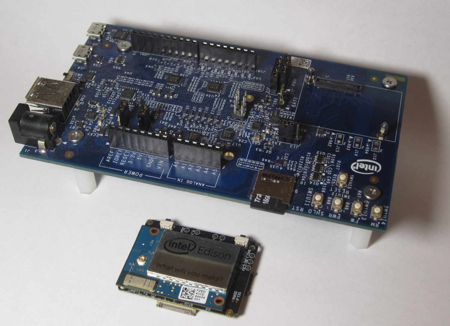
Many who see Intel Edison for the first time usually see this module already installed on the Arduino expansion board, which has a tangible size that does not involve any mobile use. Therefore, most developers do not even think that Edison can be used in a compact or portable device.
As you can see in the photo, the Intel Edison computing module itself is quite small. The main difficulty in using it in this form is that the contacts for connecting peripherals are very small. The Hirose connector used has 70 pins with a length of about 1 cm. One solution to this problem is the Xadow Wearable Kit for Intel Edisonfrom Seeed, containing the necessary adapters and small sensors, allowing you to develop a truly compact wearable device.
The kit consists of small expansion cards with various functionalities, which are connected using a flexible flat cable FCC. The boards can be connected one after another as a garland, forming the necessary functionality of the device.
Here is what goes into this kit:

- Xadow - Edison - the main connector for connecting Intel Edison.
- Xadow - 3Axis Accelerometer - acceleration sensor along three axes.
- Xadow - Edison Programmer - module for connecting to a computer via USB.
- Xadow - Barometer BMP 180 - barometer and thermometer.
- Xadow - Edison SD - module for connecting an SD card.
- Battery - a battery.
- Xadow - Q Touch Sensor - touch buttons.
- Digital RGB LED Flexi-Strip is a tape of five controllable RGB LEDs.
- Xadow - NFC - NFC reader.
- Xadow - Breakout - a board with connectors for connecting conventional sensors.
- Xadow - Buzzer - tweeter.
- Xadow - Vibration Motor - vibration motor.
- Xadow - OLED - monochrome OLED display with a resolution of 128x64.
- NFC Tags - Three 3 NFC Tags.
- FFC cable package - a set of loops.
- Power cable White, Red, Yellow - multi-colored postings.
Remarks
Before starting to describe the work, I want to immediately pay attention to some features and problems that arose during my work and possible methods for solving them. Firstly, I immediately recommend updating the firmware of the board .
The current version can be viewed with the command
configure_edison –versionAt the time of writing, this is 159.
It is also advisable to update the installed libraries. There must be an internet connection.
opkg update
opkg upgrade
All examples in the article are for the Arduino IDE. The developer of the Seeed kit, cites only them.
I tried to use the board both through Intel XDK for IoT and through C ++, but nothing worked.
Perhaps this is due to the fact that the board is schematically different from the standard Arduino expansion board. There are still some problems when working with I2C. The accelerometer does not always work stably. He worked stably in the game when he was connected after the OLED display, maybe this is a coincidence, or maybe there is some peculiarity. I still could not get the barometer and thermometer board to work.
Sometimes the connection to the board from the Arduino IDE was lost, the sketch could not be compiled and transmitted. If this happens, you need to stop the working sketch on the board:
systemctl stop clloaderthen you need to clear the / sketch folder, then close all running Arduino IDEs on the computer. Turn off the Intel Edison board (shutdown now), then turn it on again by holding the PWR button until the LED lights up.
Sometimes it may be necessary to make the sketch run when power is applied to the Edison board. This can be done as follows. Create the folder /etc/init.d, in it create the automateSketch.sh file, in which to place two lines:
#!/bin/sh
exec /sketch/sketch.elf /dev/ttyGS0 /dev/ttyGS0
Make the file executable:
chmod +x automateSketch.shAnd add it to the download:
update-rc.d automateSketch.sh defaultsBeginning of work
All drivers for Intel Edison must be installed on your computer.
All work with the modules from this set is done through Arduino sketches, so if you have not yet installed the Arduino IDE development environment, you need to install it. You can download it from the website www.arduino.cc .
To work with the board, you need to connect the Xadow-Edison Programmer module. Both USB sockets must be connected, as the power supply is supplied one at a time, and the second provides an Arduino IDE connection. The switch on the board must be in the Device position. In the Arduino IDE, you must select the Intel Edison board through the Boards Manager.
After the system boots to Edison (about 30 seconds), you need to find the virtual port number in the device manager on the computer.
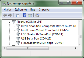
Intel Edison Virtual Com Port (COM25) - must be selected in the Arduino IDE.
USB Serial Port (COM29) - can be used to connect to the console, for example, through Putty.
Connecting Modules
I recommend making any connections by disconnecting the power from the Intel Edison module. This will reduce the likelihood of elements failing. Also, sometimes with a hot connection, sketches cease to load normally and still have to turn the board off and on.
All modules are connected using FFC - a flexible flat cable. They differ in length and width. The width should correspond to the connector into which it is connected. All loops are connected with the blue part up and the contacts down. There are two types of connectors on the boards. The first opens up like a lid. Tearing it off, the cable should be easily inserted until it stops, about 3 mm. Close the lid.
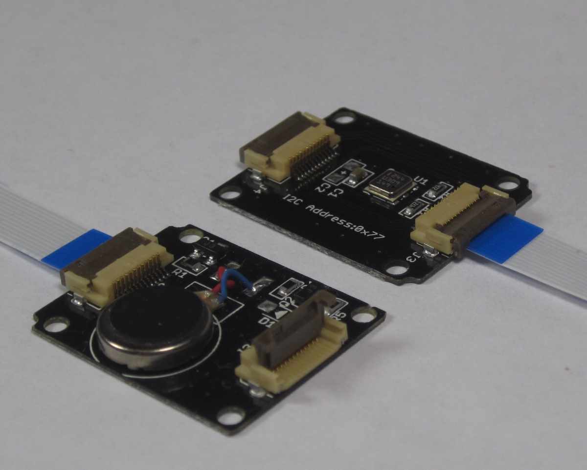
The second type of connector is a retractable clip. It is less convenient to use. It must be pried around the edges and pulled out about 1 mm. We must act carefully, for example, I managed to break one of the legs of the connector. Insert the cable with a little effort until it stops, it should go in about 3 mm. Then close the connector by sliding it back. He closes with some effort.
The inserted cables should hold well and not fall out of the connectors themselves.

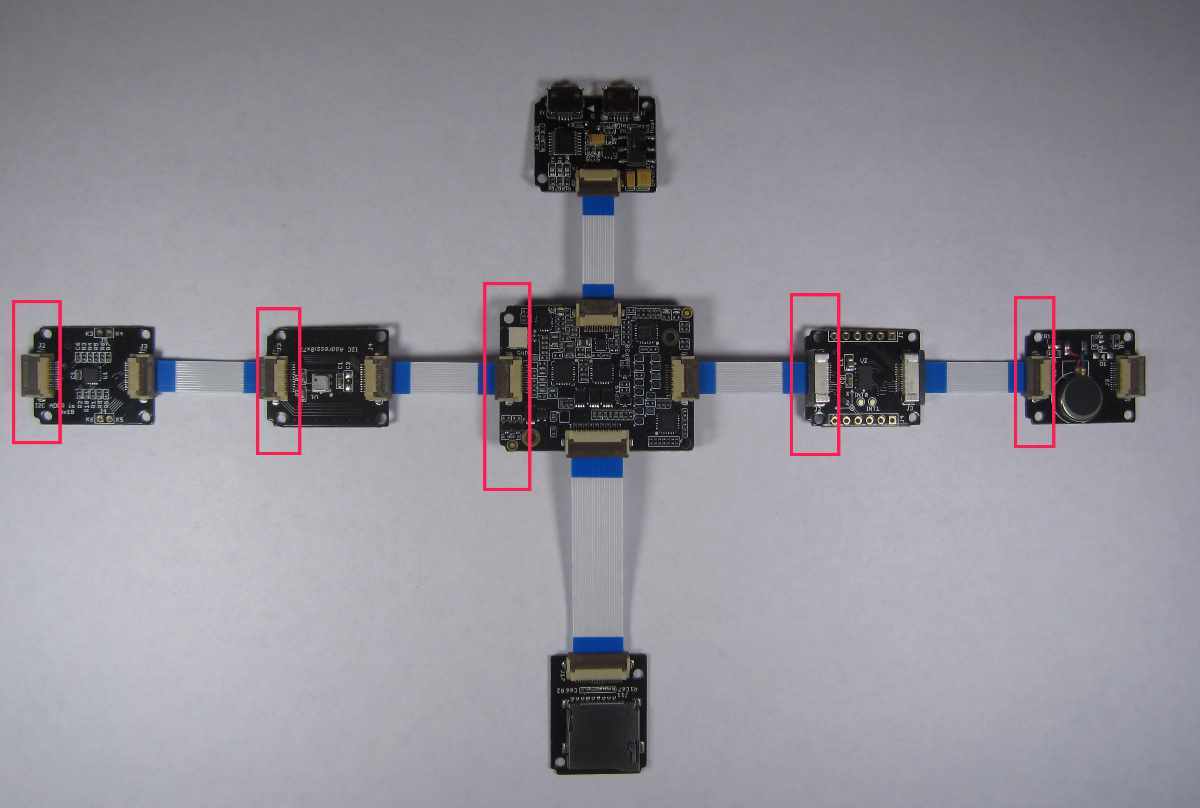
All modules have connectors on two sides, but each module and the main board have bevelled corners on one side. All boards should be located so that all of these labels are on all modules on one side, for example, on the left.
Arduino Library
For work with modules libraries are required. You can get them at github.com/Seeed-Studio/Xadow_Edison_Demos. You need to download the entire archive with one .ZIP file. Most likely, you won’t be able to install the entire archive at once, so folders with the necessary libraries will need to be added through the development environment menu.
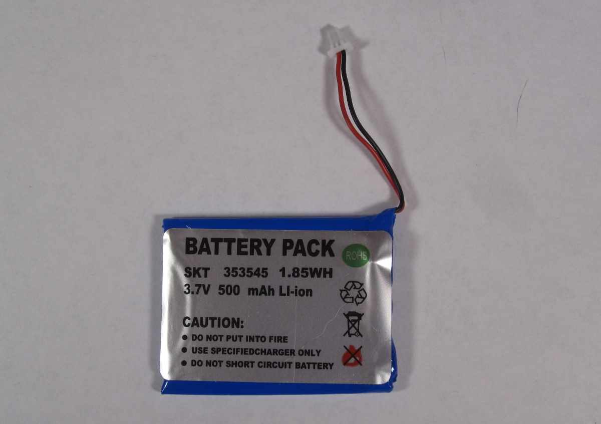
Battery
Normal Li-Ion battery. Voltage is 3.7V. Capacity 500 mAh.
Xadow - Edison
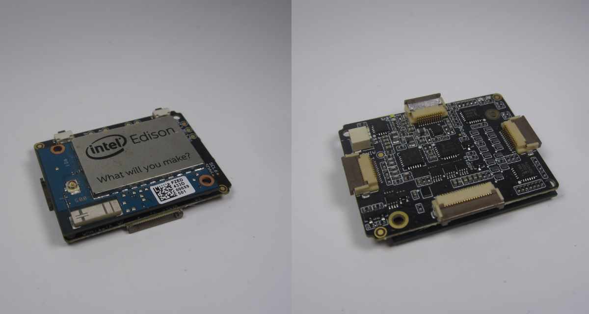
This is the main board for connecting the Edison module. In size, it is slightly larger than the Edison module itself. Installed in the connector, Edison holds firmly without fixing screws. But for reliability, you can use the screws from the Arduino module.
There is a connector for connecting the battery. Four slots for expansion cards are located around the perimeter. Top slot for connecting the Edison-Programmer board. Lateral - for boards with sensors and actuators. Bottom wide slot for connecting a module with an SD card.
There are two buttons PWR and FW_RCVR. PWR allows you to turn the device on and off with a long press. 9 seconds - to turn off, 2 seconds - to turn on.
There is a small green LED next to the battery connector that shows the power mode. The experiments showed the following. If it blinks, the power comes from USB. If it is lit continuously, the connected battery is being charged. If it is not lit, the battery is charged.
Actually, this board is enough for Edison to work. Well, of course, you still need a battery.
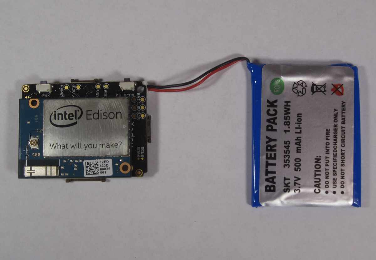
It was this compact working device that made a big impression on me. A small scarf with a battery is a miniature computer with real Linux, which you can connect to via WiFi.
Xadow - Edison Programmer
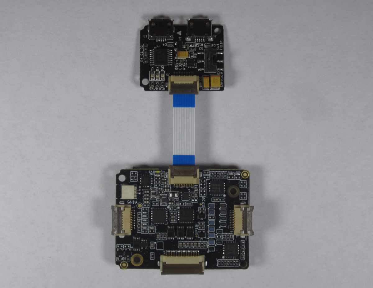
Board for connecting to a computer. Can be used for debugging and power from a computer. It contains two Micro USB connectors:
- with the inscription UART is used to connect to a computer via COM and to supply power.
- labeled Device / Host is used to work through the Arduino IDE. The operating mode of the Device or Host is selected by the switch. For Arduino, select Device.
Xadow - Edison SD
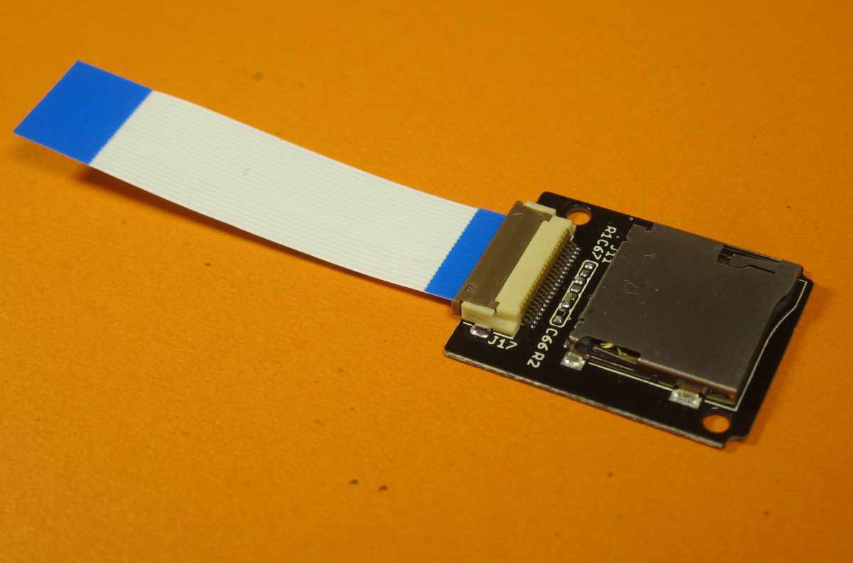
Contains a slot for connecting an SD card. It is connected to the bottom connector of the main board with the widest loop.
On devices, the SD card is located in / dev / mmcblk1
Mounting is done as usual on Linux. You need to create an empty folder somewhere, for example:
mkdir /home/dataThen mount the card in this folder:
mount /dev/mmcblk1 /home/data To automatically mount the card when loading Linux, add the line to the / etc / fstab file
/dev/mmcblk1 /home/data auto auto 0 0Xadow - OLED 12864
OLED screen with a resolution of 128x64 pixels.
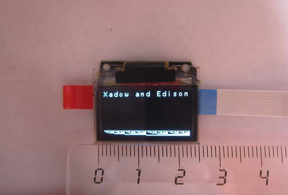
Screen description on seeed website .
The screen is connected via the I2C interface. The device address is 0x3C.
A program that displays text and just bytes.
#include
#include
void setup()
 {
  Wire.begin();
  SeeedOled.init();  //initialze SEEED OLED display
  SeeedOled.clearDisplay();          //clear the screen and set start position to top left corner
  SeeedOled.setBrightness(255);
  SeeedOled.setNormalDisplay();      //Set display to normal mode (i.e non-inverse mode)
  SeeedOled.setPageMode();           //Set addressing mode to Page Mode
  SeeedOled.setTextXY(0,0);          //Set the cursor to Xth Page, Yth Column
  SeeedOled.putString("Xadow and Edison"); //Print the String
  SeeedOled.setTextXY(7,0);          //Set the cursor to Xth Page, Yth Column
  for(int k = 0; k < 128; k++)
  {
    SeeedOled.sendData(k);
  }
}
void loop() {
}
The speed with which you can redraw the entire screen is a few frames per second.
The screen contains 8 lines, each with 16 characters.
The SeeedOLED library has the following functions:
init () - initializes the screen.
sendCommand (unsigned char command)
setBrightness (unsigned char Brightness) - sets the brightness
setHorizontalMode ()
setPageMode ()
setTextXY (unsigned char Row, unsigned char Column) - sets the position of the text cursor. If the screen is in landscape orientation, then the first parameter is the row number, the second parameter, the column number. Actually sets the position for the output of any data.
clearDisplay () - clear the screen.
sendData (unsigned char Data) - send data to the screen
putChar (unsigned char C) - character output. Code 32-127
putString (const char * String) - output string
putNumber (long long_num) - output integer
putFloat (float floatNumber, unsigned char decimal) - output float number
putFloat (float floatNumber) - output float number
drawBitmap (unsigned char * bitmaparray, int bytes) - draws a picture. The image is displayed at the current coordinates.
setHorizontalScrollProperties (bool direction, unsigned char startPage, unsigned char endPage, unsigned char scrollSpeed)
activateScroll () - enables scrolling
deactivateScroll () - disables scrolling.
setNormalDisplay () - sets a normal, not inverse display. Saves the current image.
setInverseDisplay () - changes the screen color to inverse. Saves the current image.
Xadow - Buzzer. Squeaker
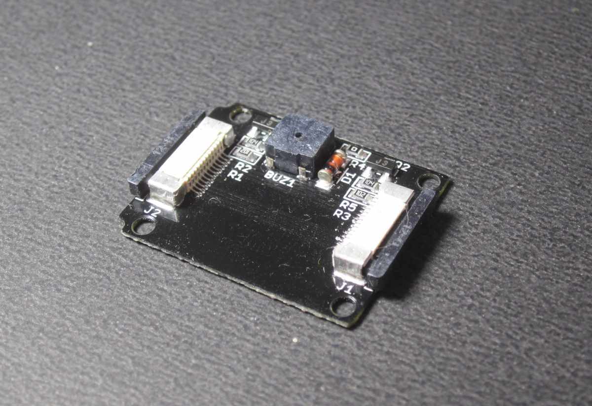
The tweeter is connected to two pins 11 and 13. They must be turned on and off simultaneously. To create a sound, you must periodically apply 0 and 1 to these two pins.
The experiments showed that it is enough to apply 1 to one of the inputs and periodically change the state of the other, the sound is also reproduced.
Sound output example:
void buzzerInit()
{
    pinMode(11,OUTPUT);
    pinMode(13,OUTPUT);
}
void buzzerOn()
{
    digitalWrite(11,HIGH);
    digitalWrite(13,HIGH);
}
void buzzerOff()
{
    digitalWrite(11,LOW);
    digitalWrite(13,LOW);
}
void buzzerSignal(int t_ms)
{
    unsigned long cur = millis();
    while((millis()-cur) < t_ms )
    {
        buzzerOn();
        delayMicroseconds(150);
        buzzerOff();
        delayMicroseconds(150);
    }
}
void setup()
{
    buzzerInit();
    buzzerSignal(1000);
}
void loop()
{
}
Since the reproduction is done programmatically, the sound is not particularly clear. It would be better to use PWM modulation.
Interestingly, the analogue of this sketch that I rewritten to Intel XDK for IoT and C ++ did not work for me. The tweeter was just silent.
Xadow - Vibration Motor. Vibration motor
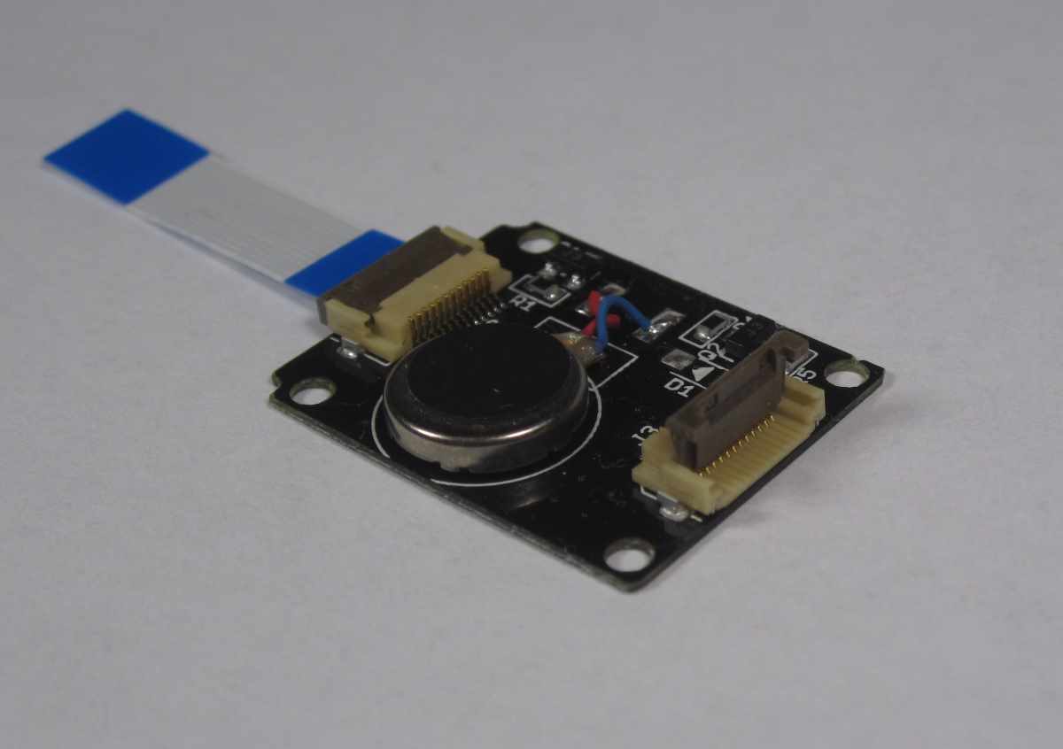
Driving a vibrator is similar to working with a squeaker. It can be turned on and off.
// Xadow - Vibro
void vibroInit()
{
    pinMode(11,OUTPUT);
    pinMode(10,OUTPUT);
}
void vibroOn()
{
    digitalWrite(11,HIGH);
    digitalWrite(10,HIGH);
}
void vibroOff()
{
    digitalWrite(11,LOW);
    digitalWrite(10,LOW);
}
void setup()
{
    vibroInit();
    vibroOn();
    delay(500);
    vibroOff();
}
void loop()
{
}
As in the case of the squeaker, you can control one pin, pre-setting on the other 1.
Xadow - Q Touch Sensor

The board contains three touch buttons on the back side. Connection via I2C protocol at address 0x1B.
The sensitivity is quite high. It works even after several layers of paper or film. Therefore, in the final device, the buttons can be hidden behind the drawn pictures.
The program from the example displays the number of the pressed button:
#include
#include "Seeed_QTouch.h"
void setup()
{
    Serial.begin(9600);
    Wire.begin();
}
void loop()
{
    int tn = QTouch.touchNum();
    if(tn>=0)
    {
        Serial.print("KEY");
        Serial.print(tn);
        Serial.println(" touched");
    }
    delay(10);
}
Xadow - NFC
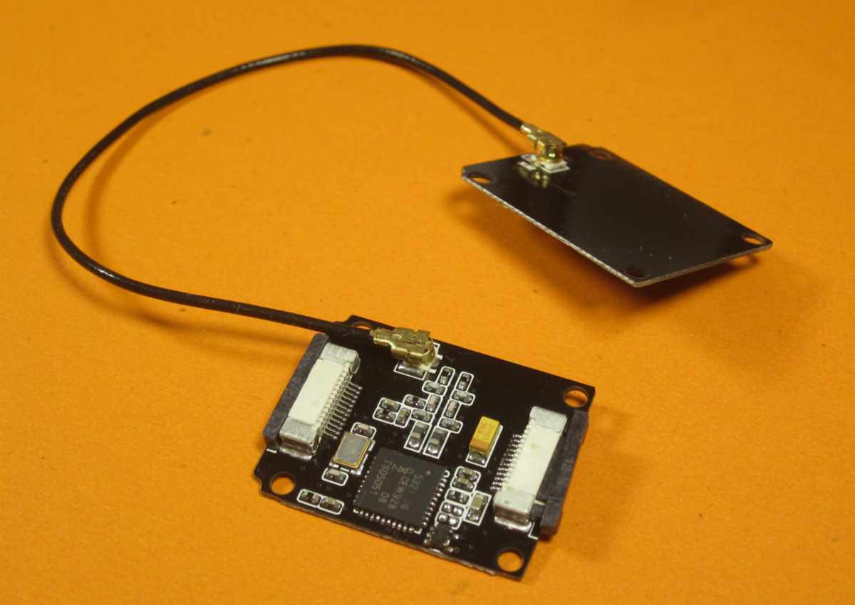
http://www.seeedstudio.com/wiki/Xadow_-_NFC
NFC reader. Connection via I2C, SPI, UART. It operates at a frequency of 13.56 MHz. It works for reading and writing. Supports ISO14443 Type A and Type B protocol. Supports P2P connection. There is an antenna and wire for connecting it.
There are three clean NFC tags in the kit where you can record information.
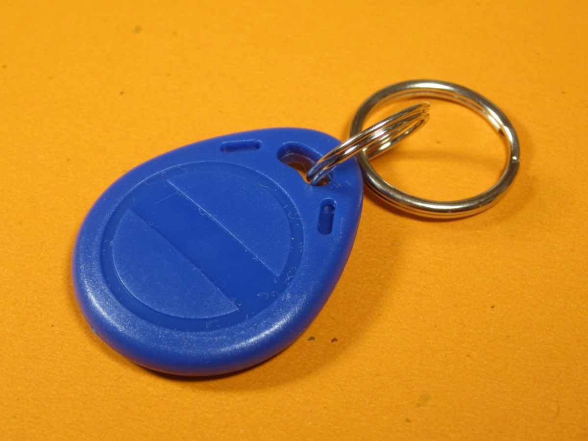
To work with this module, you need to install the NDEF, PN532, PN532_HSU, PN532_I2C, PN532_SPI libraries from the Seeed common example library.
To test the tags and the reader, you can take the program from the examples, which reads the value from the presented tag and displays it in the NDEF-> readTag console. The
tags that come with the kit have serial numbers. They are not formatted and produce approximately the following:
Tag is not NDEF formatted.
NFC Tag - Mifare Classic
UID 6E A5 0B 01
To record any information on tags, you must first format them. Example NDEF-> FormatTag:
To write information to a label, you can take the example NDEF-> WriteTag.
Here is the result of reading from the recorded label:
NFC Tag - Mifare Classic
UID 5E B1 FB 01
NDEF Message 1 record, 28 bytes
  NDEF Record
    TNF 0x1 Well Known
    Type Length 0x1 1
    Payload Length 0x18 24
    Type 55  U
    Payload 00 49 6E 74 65 6C 20 45 64 69 73 6F 6E 20 77 69 74 68 20 58 61 64 6F 77  .Intel Edison with Xadow
    Record is 28 bytes
Xadow - 3Axis Accelerometer

Acceleration sensor. Works on three axes. Measured range up to ± 16 g. Connected via I2C protocol with address 0x53. Used chip ADXL345. It is necessary to connect the DigitalAccelerometer_ADXL345 library from the kit.
There are four measuring ranges: ± 2g, ± 4g, ± 8g, ± 16g. They differ in accuracy and conversion factor.
Datasheet on the chip pdf1.alldatasheet.com/datasheet-pdf/view/254714/AD/ADXL345.html
Data is given in 16-bit numbers. In additional code. The library gives numbers as int, so they need to be adjusted, for example, like this:
void correct(int &a)
{
 if( a > 32767 )
     a = -(65536 - a);
}
If the range is ± 2g, then the resulting value should be divided by 256. As I already wrote, I had difficulties with its work. Sometimes it disappeared and I2C errors appeared in the Linux console. But there was no such behavior when I connected the screen and then the accelerometer to the main module.
Xadow - Barometer BMP 180

Barometer and thermometer. The pressure measurement range is 300-1100 hPa (which corresponds to -500 .. + 9000 m above sea level). Connected via I2C at 0x77.
Unfortunately, I still couldn’t get it to work. Perhaps it was a mistake in the I2C interface, maybe I messed up the module by connecting it from the wrong side.
Xadow - Breakout
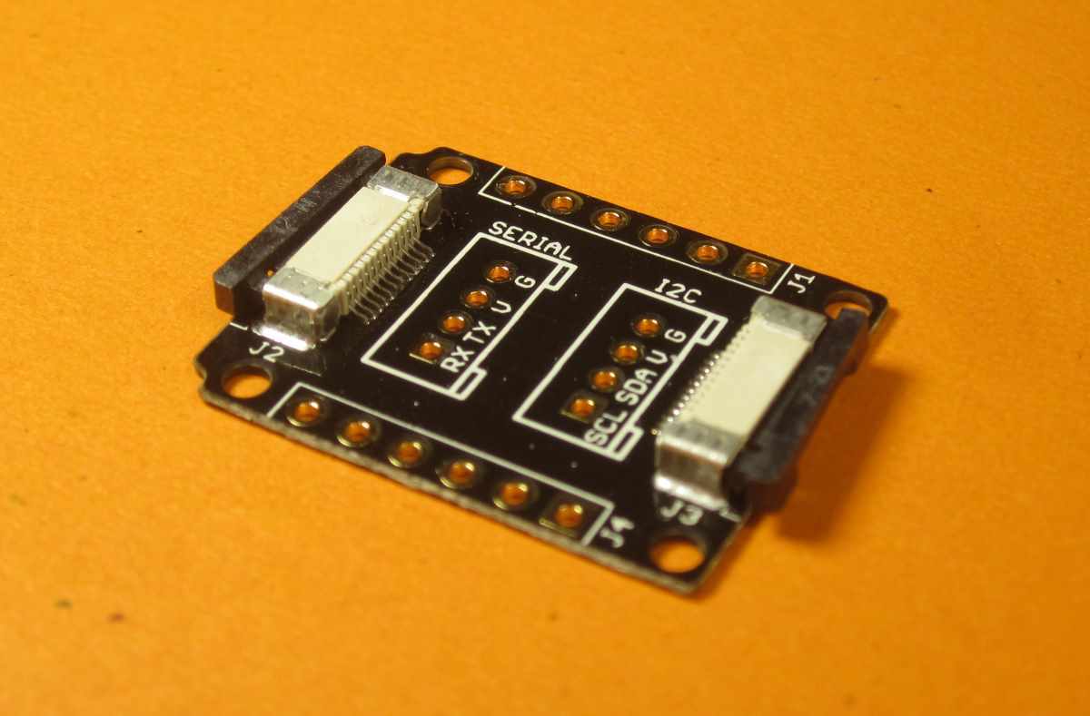
Board for connecting conventional sensors. Contains contacts 3.3V, SCL, SDA, TX0, GND, SCK, MOS1, MOS0, A5. Contains two pads for placing a connector to which standard seeed modules can be connected. One signed by Serial, the other by I2C. Used to connect LED strips.
Digital RGB LED Flexi-Strip
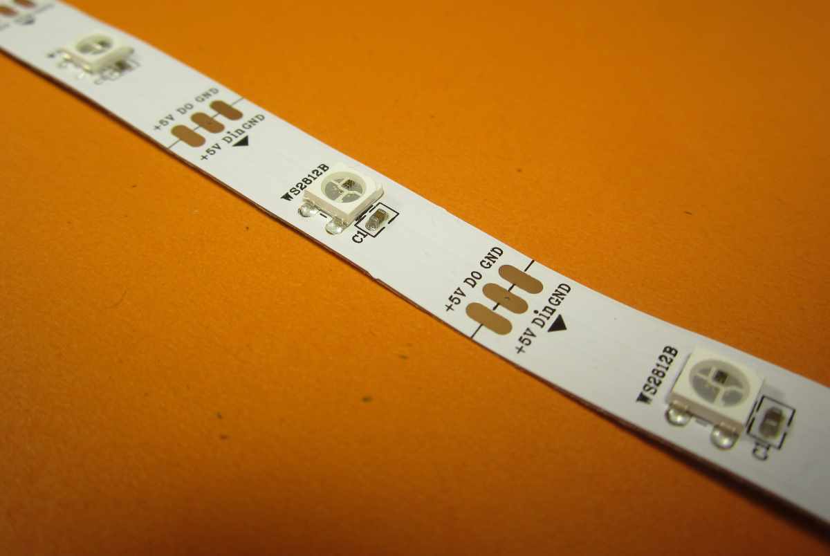
5 LED strip. RGB LEDs WS2812B. They are controlled by a single wire.
In order to connect them, you have to solder a little. You need to use the Xadow-Breakout board.

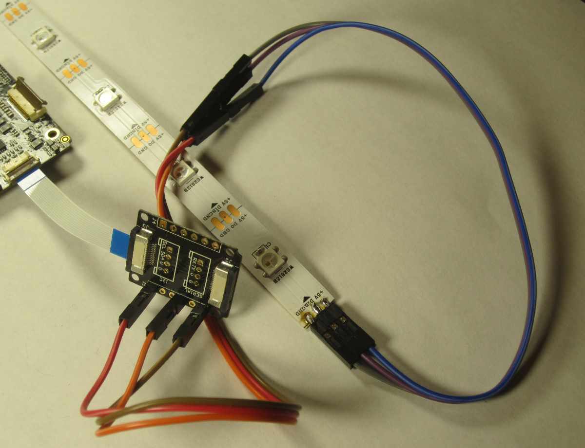
Information transmission is done programmatically, so sometimes there are errors in the transmission of information and random flash of LEDs occur.
Running light program:
#include
#include "Seeed_ws2812.h"
#define SIG_PIN 12
#define LEN_NUM 5
WS2812 strip = WS2812(LEN_NUM, SIG_PIN);
void setup() {
  strip.begin();
  //Serial.begin(115200);
}
int pos = 0;
void loop() {
  strip.WS2812SetRGB(pos,255,0,0);
  strip.WS2812Send();
  delay(100);
  strip.WS2812SetRGB(pos,0,0,0);
  strip.WS2812Send();
  delay(100);
  pos = (pos+1)%LEN_NUM;
}
Game creation
I wanted to collect something from this set. The idea of the next game came to mind. The game box contains a ribbon of LEDs on top. Lights may light up on it. Depending on the place where they turned on and the color, you need to tilt the box 45 degrees in a certain direction. For example, if the central LED lights up green, then you need to tilt forward from yourself. If the central one turns red, then you need to tilt it towards you. If the lateral extreme green LED on the right lights up, then the tilt is made to the right, if it lights up the same, but in red, then the tilt should be done to the left. The game not only checks the reaction, but also makes you first figure out and then make a decision.
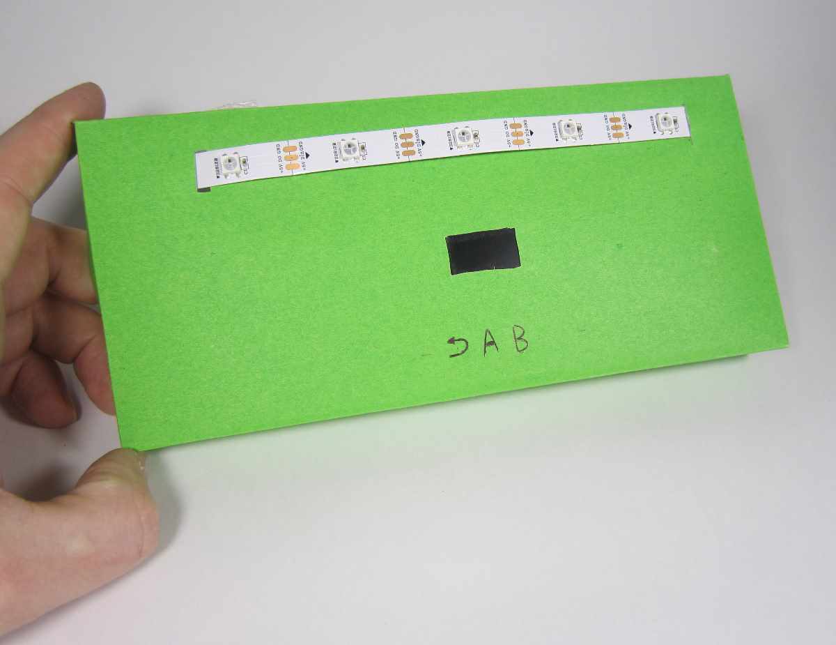
We will need:
- gyroscope,
- OLED screen,
- LED strip
- expansion module for connecting the tape,
- board with buttons,
- battery.
We connect everything in the following order. From the side of the battery connector, we connect Breakout, then touch buttons. On the other hand is a screen and then a gyroscope. I glued the case out of thick colored paper. I cut a hole for the screen. The board with the buttons is placed under the screen. As I wrote earlier, the buttons are very sensitive. On the front side above the buttons, I drew their notation.
All boards are glued with tape over paper so as not to spoil anything.
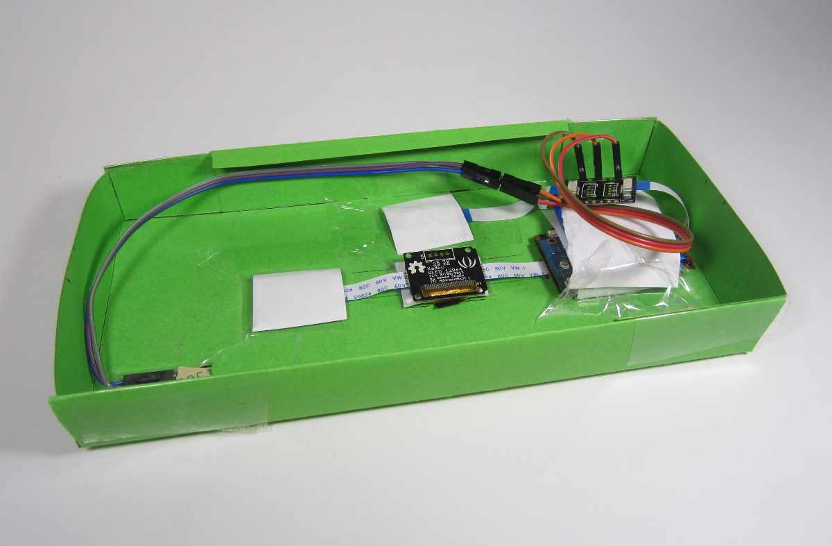
On Linux, autostart of the sketch is configured.
The game starts by pressing the PWR button for about 9 seconds on the main module. Turns off by pressing for 3 seconds.
When the game starts, a menu appears from which you can start the game with the A button or call up the game help with the B button. Return from the help with the arrow button.
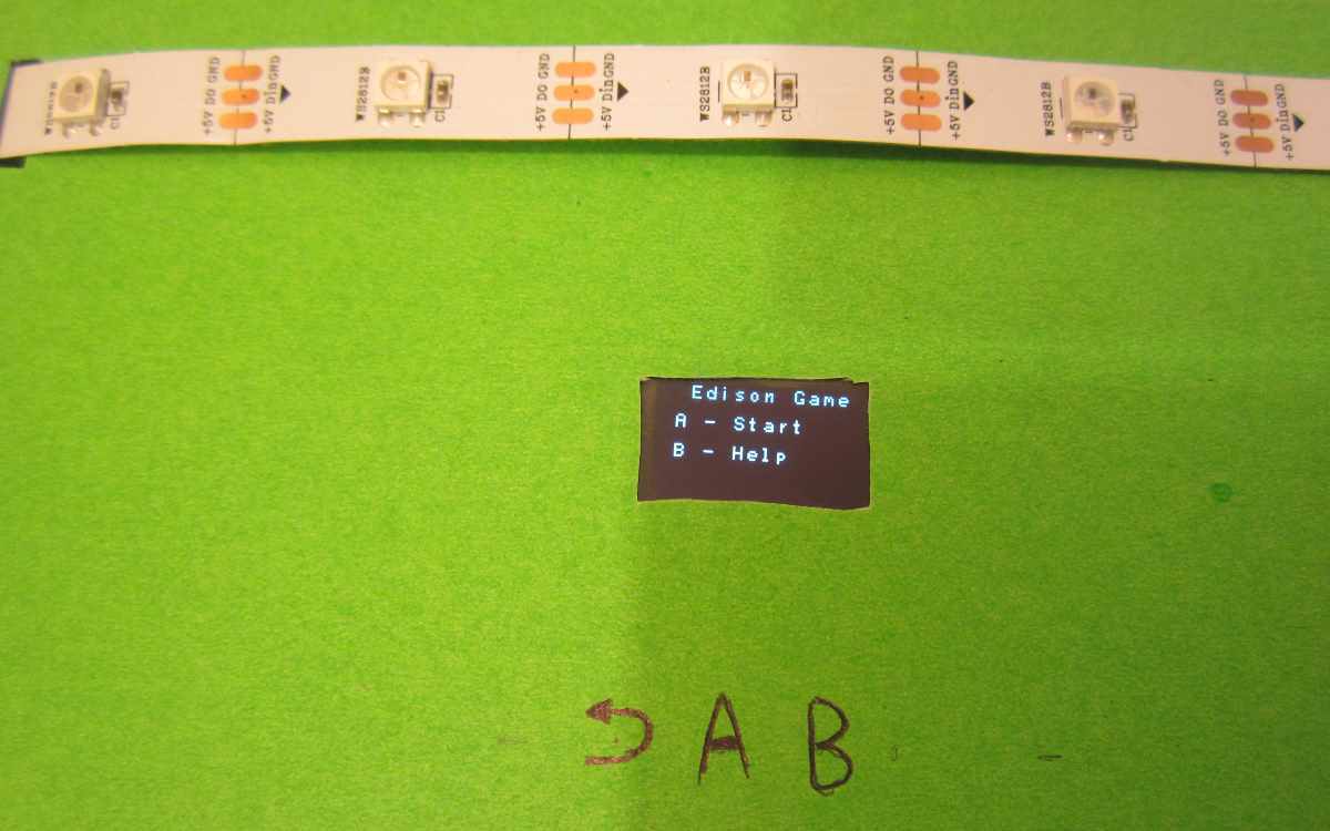
The game consists of five series. In each, a random LED lights up and you need to tilt the box in the appropriate direction. With the right turn, You Win! If it’s wrong or if the available time is over, then You Lose!
I put all the game code in one file and tried to make it as simple as possible, so that it was easier to understand.
Game Sketch Source Code
#include
#include
#include
#include
#include
// состояния игры
const int stateMenu = 1;
const int stateCount = 3;
const int stateHelp = 4;
// кнопки
const int keyBack = 0;
const int keyA = 1;
const int keyB = 2;
// LED лента
const int ledSigPin =  12;
const int numLed = 5;
// ответы
const int answerLeft = 1;
const int answerRight = 2;
const int answerUp = 3;
const int answerDown = 4;
const int colorGreen = 1;
const int colorRed = 2;
const int numLevels = 6;
const int answerID = 5;
const int angleScale = 100;
const int angleReact = 100;//тангенс угла срабатывания * angleScale
int numWins;// число побед
int numLosts;// число проигрышей
int gameState;// состояние игры
const int numSets = 5;// число сетов в игре
// кодирование уровней
int levels[numLevels][numLed+1] = {  {colorGreen,0,0,0,0,answerLeft},
                             {colorRed,0,0,0,0,answerRight},
                             {0,0,0,0,colorGreen,answerRight},
                             {0,0,0,0,colorRed,answerLeft},
                             {0,0,colorGreen,0,0,answerUp},
                             {0,0,colorRed,0,0,answerRight}};
// правильный ответ
int rightAnswer;
WS2812 strip = WS2812(numLed, ledSigPin);
ADXL345 adxl;
// текущий уровень игры
int gameLevel;
// инициализация акселерометра
void initAccel()
{
  adxl.powerOn();
  //set activity/ inactivity thresholds (0-255)
  adxl.setActivityThreshold(75); //62.5mg per increment
  adxl.setInactivityThreshold(75); //62.5mg per increment
  adxl.setTimeInactivity(10); // how many seconds of no activity is inactive?
  //look of activity movement on this axes - 1 == on; 0 == off
  adxl.setActivityX(1);
  adxl.setActivityY(1);
  adxl.setActivityZ(1);
  //look of inactivity movement on this axes - 1 == on; 0 == off
  adxl.setInactivityX(1);
  adxl.setInactivityY(1);
  adxl.setInactivityZ(1);
  //look of tap movement on this axes - 1 == on; 0 == off
  adxl.setTapDetectionOnX(0);
  adxl.setTapDetectionOnY(0);
  adxl.setTapDetectionOnZ(1);
  //set values for what is a tap, and what is a double tap (0-255)
  adxl.setTapThreshold(50); //62.5mg per increment
  adxl.setTapDuration(15); //625us per increment
  adxl.setDoubleTapLatency(80); //1.25ms per increment
  adxl.setDoubleTapWindow(200); //1.25ms per increment
  //set values for what is considered freefall (0-255)
  adxl.setFreeFallThreshold(7); //(5 - 9) recommended - 62.5mg per increment
  adxl.setFreeFallDuration(45); //(20 - 70) recommended - 5ms per increment
  //setting all interrupts to take place on int pin 1
  //I had issues with int pin 2, was unable to reset it
  adxl.setInterruptMapping( ADXL345_INT_SINGLE_TAP_BIT,   ADXL345_INT1_PIN );
  adxl.setInterruptMapping( ADXL345_INT_DOUBLE_TAP_BIT,   ADXL345_INT1_PIN );
  adxl.setInterruptMapping( ADXL345_INT_FREE_FALL_BIT,    ADXL345_INT1_PIN );
  adxl.setInterruptMapping( ADXL345_INT_ACTIVITY_BIT,     ADXL345_INT1_PIN );
  adxl.setInterruptMapping( ADXL345_INT_INACTIVITY_BIT,   ADXL345_INT1_PIN );
  //register interrupt actions - 1 == on; 0 == off
  adxl.setInterrupt( ADXL345_INT_SINGLE_TAP_BIT, 1);
  adxl.setInterrupt( ADXL345_INT_DOUBLE_TAP_BIT, 1);
  adxl.setInterrupt( ADXL345_INT_FREE_FALL_BIT,  1);
  adxl.setInterrupt( ADXL345_INT_ACTIVITY_BIT,   1);
  adxl.setInterrupt( ADXL345_INT_INACTIVITY_BIT, 1);
}
void initGame()
{
  SeeedOled.clearDisplay();
  SeeedOled.setNormalDisplay();
  SeeedOled.setPageMode();
  switchToMenu();
}
void setup()
{
    strip.begin();
    SeeedOled.init();
    initAccel();
    initGame();
}
void cleanLED()
{
  for( int led = 0; led < numLed; led++ )
      strip.WS2812SetRGB(led,0,0,0);
}
void updateLED()
{
  strip.WS2812Send();
}
void drawMenu()
{
  SeeedOled.clearDisplay();
  SeeedOled.setTextXY(0,2);
  SeeedOled.putString("Edison Game");
  SeeedOled.setTextXY(2,1);
  SeeedOled.putString("A - Start");
  SeeedOled.setTextXY(4,1);
  SeeedOled.putString("B - Help");
}
void drawHelp()
{
  SeeedOled.clearDisplay();
  char *messages[] = {    "Center green -",
    "tilt forward." ,
    "Center red -" ,
    "tilt backward.",
    "Green edge -" ,
    "tilt same side." ,
    "Red edge - tilt",
    "other side."
 };
   for( int k = 0; k < 8; k++ )
   {
      SeeedOled.setTextXY(k,0);
      SeeedOled.putString(messages[k]);
   }
}
void makeNewLevel()
{
    gameLevel = rand() % numLevels;
    rightAnswer = levels[gameLevel][answerID];
}
void showGameStart()
{
  SeeedOled.clearDisplay();
  SeeedOled.setTextXY(0,0);
  SeeedOled.putString("Press Start");
}
int getKeys()
{
    int tn = QTouch.touchNum();
    return tn;
}
int haveTime = 20;
void showGameLevel()
{
  for( int k = 0; k < numLed; k++ )
  {
     int color = levels[gameLevel][k];
     switch(color)
     {
         case colorRed  : strip.WS2812SetRGB(k,255,0,0); break;
         case colorGreen: strip.WS2812SetRGB(k,0,255,0); break;
         default        : strip.WS2812SetRGB(k,0,0,0);
     }
  }
  updateLED();
}
void switchToSets()
{
  numWins = 0;
  numLosts = 0;
  switchToPlay();
}
//------------------------------------
void switchToPlay()
{
  cleanLED();
  updateLED();
  SeeedOled.clearDisplay();
  SeeedOled.setTextXY(3,3);
  SeeedOled.putString("Get ready!");
  int waitTime = 2000 + (rand()%4)*500;
  delay(waitTime);
  makeNewLevel();
  SeeedOled.setTextXY(3,3);
  SeeedOled.putString("          ");
  haveTime = 100;
  gameState = stateCount;
}
void doPlay()
{
  if( haveTime >= 0 )
  {
    SeeedOled.setTextXY(3,1);
    char str[100];
    sprintf(str,"-- TILT NOW --");
    SeeedOled.putString(str);
    SeeedOled.setTextXY(5,6);
    sprintf(str,"%d  ",haveTime);
    SeeedOled.putString(str);
    showGameLevel();
    int answerID = getAnswerID();
    haveTime--;
    if( answerID !=0 || haveTime < 0)
    {
      char *message;
      if( answerID != rightAnswer || haveTime < 0)
      {
        numLosts++;
        message = "You lose!";
      }
      else
      {
        numWins++;
        message = "You win!";
      }
      cleanLED();
      updateLED();
      SeeedOled.clearDisplay();
      SeeedOled.setTextXY(3,4);
      SeeedOled.putString(message);
      delay(1000);
      if( numWins + numLosts == numSets )
      {
        switchToMenu();
      }
      else
      {
        switchToPlay();
      }
    }
  }
}
//-----------------------
void switchToHelp()
{
    drawHelp();
    gameState = stateHelp;
    cleanLED();
    updateLED();
}
void doHelp()
{
  cleanLED();
  updateLED();
  int key = getKeys();
  if( key == keyBack )
      switchToMenu();
}
//-----------------------
void switchToMenu()
{
  drawMenu();
  gameState = stateMenu;
  cleanLED();
  updateLED();
}
void doMenu()
{
  int key = getKeys();
  if( key == keyA )
      switchToSets();
    if( key == keyB )
      switchToHelp();
}
//-----------------------
void correct(int &a)
{
 if( a > 32767 )
     a = -(65536 - a);
}
int  getAnswerID()
{
  int x,y,z;
  adxl.readXYZ(&x, &y, &z);
  correct(x);
  correct(y);
  correct(z);
  int v1 = angleReact;
  if( z != 0 )
      v1 = y*angleScale/z;
  if( v1 > angleReact )
    return answerRight;
  if( v1 < -angleReact )
    return answerLeft;
  int v2 = angleReact;
  if( z != 0 )
      v2 = x*angleScale/z;
  if( v2 > angleReact )
    return answerUp;
  if( v2 < -angleReact )
    return answerDown;
    return 0;
}
void gameStep()
{
  switch(gameState)
  {
    case stateCount: doPlay();break;
    case stateMenu:  doMenu();break;
    case stateHelp:  doHelp();break;
  }
}
void loop()
{
    gameStep();
    delay(10);
} 