Arduino Robot Vacuum Cleaner
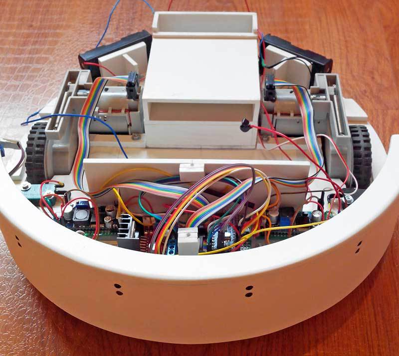
Despite the fact that at geektimes there are already several articles about robotic vacuum cleaners on arduino here and here , I think it will not be superfluous to publish another project. Moreover, it is made a little closer to store models and, since the project is constantly developing, it will surpass some of them in functionality over time. I publish this post with the permission of the developer of this robot vacuum cleaner, since the author does not have the opportunity to publish articles from her account. Therefore, the article will be in the form of a short interview with the creator mixed with schemes, photos and the code of a robot vacuum cleaner. But let's start with a video demonstration of cleaning the room with this vacuum cleaner.

So, let's start with the design and principle of operation of the vacuum cleaner.

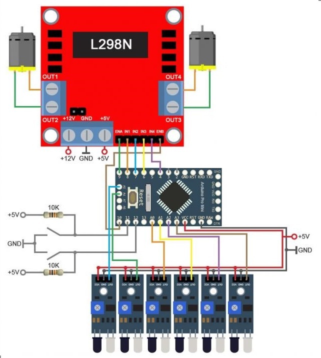
The diagram shows that the vacuum cleaner is equipped with 6 infrared sensors. They work when the vacuum cleaner approaches the obstacle, giving the command to stop and turn around without crashing into it. If none of the 6 sensors worked and the robot vacuum cleaner collides with an obstacle, then one of the 2 switches that connect the bumper (which contains the IR sensors) and the robot body is triggered.
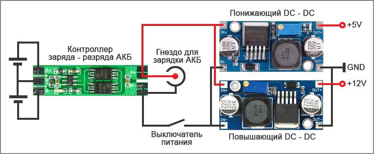
Attentive readers have noticed that the robot power is not shown in the diagram. Here the solution is quite standard, 4 batteries of the 18650 format are used, two pairs connected in series through the battery charge-discharge controller. Further, up and down DC-DC converters are connected from the controller through a switch. + 12 volts feeds the wheel motors and front brush motors. +5 volts feeds the rest of the electronics. The turbine is powered by 7-8 volts, so a converter is not needed for it. It looks like this:

As a result, the list of main components looks like this:
arduino pro mini
L298N Motor Driver Module
wheels
boost converter
step-down converter
IR sensor 6 pcs
charge-discharge controller
impeller for a turbine (about 200 rubles)
PVC for manufacturing a
battery case 18650 4 pcs.
2 motors for brushes (model is not very important)
1 motor for a turbine
2 collision switches.
One of the options for a sketch for chaotic cleaning
Well, a short interview with the author of this project. The author's name is Dmitry Ivanov, lives in Sochi.
- Dmitry, how did you get the idea to make a robot vacuum cleaner?
- I saw a video on YouTube where a robot vacuum cleaner was cleaning, wanted to buy one, but when I looked at the price, I thought and decided to do it myself. At first I made the first version of the robot, it had weak motors on wheels, a fixed container for debris and dust, few obstacle sensors, and I made the second version, devoid of these shortcomings.
- How much money and time did it take to make it?
“About 5000 thousand rubles. plus two months of work ”
- What was the most difficult during the construction process?
The most difficult thing is to make a casing and a turbine, to fit all the details.
- Any plans to continue improving the robot?
The plans are to paint the case, make several cleaning modes, connect the bluetooth module and write a program for the phone on the android (mode control, manual control, display of battery charge). Well, make a blue backlight for beauty under a vacuum cleaner.
A collection of over 100 educational materials on arduino for beginners and pros can be found here .
PS The online course on Arduino at Gimetays is here. At this optimistic moment, I think, we will finish the story about this version of the robot vacuum cleaner, although there are many interesting moments unlit. And so we conclude with a question:

So, let's start with the design and principle of operation of the vacuum cleaner.

The diagram shows that the vacuum cleaner is equipped with 6 infrared sensors. They work when the vacuum cleaner approaches the obstacle, giving the command to stop and turn around without crashing into it. If none of the 6 sensors worked and the robot vacuum cleaner collides with an obstacle, then one of the 2 switches that connect the bumper (which contains the IR sensors) and the robot body is triggered.
Attentive readers have noticed that the robot power is not shown in the diagram. Here the solution is quite standard, 4 batteries of the 18650 format are used, two pairs connected in series through the battery charge-discharge controller. Further, up and down DC-DC converters are connected from the controller through a switch. + 12 volts feeds the wheel motors and front brush motors. +5 volts feeds the rest of the electronics. The turbine is powered by 7-8 volts, so a converter is not needed for it. It looks like this:

As a result, the list of main components looks like this:
arduino pro mini
L298N Motor Driver Module
wheels
boost converter
step-down converter
IR sensor 6 pcs
charge-discharge controller
impeller for a turbine (about 200 rubles)
PVC for manufacturing a
battery case 18650 4 pcs.
2 motors for brushes (model is not very important)
1 motor for a turbine
2 collision switches.
One of the options for a sketch for chaotic cleaning
here
#define mot_ena 9 // pin of the left motor
PWM #define mot_in1 8 // pin of the left motor
#define mot_in2 7 // pin of the left motor
#define mot_in3 6 // pin of the right motor
#define mot_in4 4 // pin of the right motor
#define mot_enb 10 // PWM pin of the right motor
#define ir_1 A0 // pin 1 of the IR sensor
#define ir_2 A1 // pin 2 of the IR sensor
#define ir_3 A2 // pin 3 of the IR sensor
#define ir_4 A3 // pin 4 of the IR sensor
#define ir_5 A4 // pin 5 of the IR sensor
#define ir_6 A5 // pin 6 of the IR sensor
#define lev_vik 11 // pin of the left switch
#define pra_vik 12 // pin of the right switch
// for aligning wheel speed
byte max_skor_lev = 254 ;
byte max_skor_prav = 244;
// ---------------------------------
byte min_skor = 0;
void setup () {
randomSeed (analogRead (A7));
// encoder pins to the input
pinMode (3, INPUT); // pin of the left encoder to the input
pinMode (2, INPUT); // pin of the right input encoder
// -------------------------
// pins for the left and right motors to the output
pinMode (mot_ena, OUTPUT) ;
pinMode (mot_in1, OUTPUT);
pinMode (mot_in2, OUTPUT);
pinMode (mot_in3, OUTPUT);
pinMode (mot_in4, OUTPUT);
pinMode (mot_enb, OUTPUT);
// -------------------------------------------
// IR pins sensors on
pinMode input (ir_1, INPUT);
pinMode (ir_2, INPUT);
pinMode (ir_3, INPUT);
pinMode (ir_4, INPUT);
pinMode (ir_5, INPUT);
pinMode (ir_6, INPUT);
// -------------------------
// pins of the left and right switches to the
pinMode input (lev_vik, INPUT);
pinMode (pra_vik, INPUT);
// ---------------------------
delay (3000);
ROB_VPERED ();
}
void loop () {
// if the left switch on the bumper is triggered
if (digitalRead (lev_vik) == LOW)
{
ROB_STOP ();
delay (200);
ROB_NAZAD ();
delay (150);
ROB_STOP ();
delay (200);
ROB_PRAV ();
delay (random (400, 1500));
ROB_STOP ();
delay (200);
ROB_VPERED ();
}
// -----------------------------------------------
// if the right switch on the bumper is
tripped if (digitalRead (pra_vik) == LOW)
{
ROB_STOP ();
delay (200);
ROB_NAZAD ();
delay (150);
ROB_STOP ();
delay (200);
ROB_LEV ();
delay (random (400, 1500));
ROB_STOP ();
delay (200);
ROB_VPERED ();
}
// -----------------------------------------------
// if 2 IR sensors are triggered
if (digitalRead (ir_2) == LOW)
{
ROB_STOP ();
delay (200);
ROB_PRAV ();
delay (random (200, 1100));
ROB_STOP ();
delay (200);
ROB_VPERED ();
}
// -----------------------------------------------
// if 3 IR sensors are triggered
if (digitalRead (ir_3) == LOW)
{
ROB_STOP ();
delay (200);
ROB_PRAV ();
delay (random (200, 1100));
ROB_STOP ();
delay (200);
ROB_VPERED ();
}
// -----------------------------------------------
// if 4 IR sensors are triggered
if (digitalRead (ir_4) == LOW)
{
ROB_STOP ();
delay (200);
ROB_LEV ();
delay (random (200, 1100));
ROB_STOP ();
delay (200);
ROB_VPERED ();
}
// -----------------------------------------------
// if 5 IR sensor is triggered
if (digitalRead (ir_5) == LOW)
{
ROB_STOP ();
delay (200);
ROB_LEV ();
delay (random (200, 1100));
ROB_STOP ();
delay (200);
ROB_VPERED ();
}
// -----------------------------------------------
// if 1 IR sensor is triggered
if (digitalRead (ir_1) == LOW)
{
ROB_PRAV ();
delay (10);
ROB_VPERED ();
}
// -----------------------------------------------
// if triggered 6 IR sensors
if (digitalRead (ir_6) == LOW)
{
ROB_LEV ();
delay (10);
ROB_VPERED ();
}
// -----------------------------------------------
}
// turn right in place
void ROB_PRAV ()
{
// left motor forward
digitalWrite (mot_in1, LOW);
digitalWrite (mot_in2, HIGH);
analogWrite (mot_ena, max_skor_lev);
// right motor back
digitalWrite (mot_in3, LOW);
digitalWrite (mot_in4, HIGH);
analogWrite (mot_enb, max_skor_prav);
}
// -----------------
// left turn in place
void ROB_LEV ()
{
// right-hand motor forward
digitalWrite (mot_in3, HIGH);
digitalWrite (mot_in4, LOW);
analogWrite (mot_enb, max_skor_prav);
// left motor back
digitalWrite (mot_in1, HIGH);
digitalWrite (mot_in2, LOW);
analogWrite (mot_ena, max_skor_lev);
}
// ---------------------
// driving forward
void ROB_VPERED ()
{
// left motor forward
digitalWrite (mot_in1, LOW);
digitalWrite (mot_in2, HIGH);
analogWrite (mot_ena, max_skor_lev);
// right motor forward
digitalWrite (mot_in3, HIGH);
digitalWrite (mot_in4, LOW);
analogWrite (mot_enb, max_skor_prav);
}
// -------------------------------------
// riding back
void ROB_NAZAD ()
{
// left motor back
digitalWrite (mot_in1, HIGH);
digitalWrite (mot_in2, LOW);
analogWrite (mot_ena, max_skor_lev);
// right motor back
digitalWrite (mot_in3, LOW);
digitalWrite (mot_in4, HIGH);
analogWrite (mot_enb, max_skor_prav);
}
// ------------------------------------
// stop
void ROB_STOP ()
{
// left stop motor
digitalWrite (mot_in1, LOW);
digitalWrite (mot_in2, LOW);
analogWrite (mot_ena, min_skor);
// right stop motor
digitalWrite (mot_in3, LOW);
digitalWrite (mot_in4, LOW);
analogWrite (mot_enb, min_skor);
}
// --------------------------------
Well, a short interview with the author of this project. The author's name is Dmitry Ivanov, lives in Sochi.
- Dmitry, how did you get the idea to make a robot vacuum cleaner?
- I saw a video on YouTube where a robot vacuum cleaner was cleaning, wanted to buy one, but when I looked at the price, I thought and decided to do it myself. At first I made the first version of the robot, it had weak motors on wheels, a fixed container for debris and dust, few obstacle sensors, and I made the second version, devoid of these shortcomings.
- How much money and time did it take to make it?
“About 5000 thousand rubles. plus two months of work ”
- What was the most difficult during the construction process?
The most difficult thing is to make a casing and a turbine, to fit all the details.
- Any plans to continue improving the robot?
The plans are to paint the case, make several cleaning modes, connect the bluetooth module and write a program for the phone on the android (mode control, manual control, display of battery charge). Well, make a blue backlight for beauty under a vacuum cleaner.
A collection of over 100 educational materials on arduino for beginners and pros can be found here .
PS The online course on Arduino at Gimetays is here. At this optimistic moment, I think, we will finish the story about this version of the robot vacuum cleaner, although there are many interesting moments unlit. And so we conclude with a question:
Only registered users can participate in the survey. Please come in.
Do you need more articles on this robot cleaner?
- 29% Yes, I would like to know about the manufacture of the case 96
- 7.5% Yes, I would like to know about creating an application for controlling a vacuum cleaner from a smartphone 25
- 57.5% Yes, both topics are interesting 190
- 5.7% No, everything is already clear. 19
