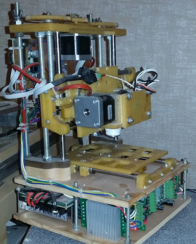
3D printer using a rack-and-pinion drive
Reason for developing this 3D printer design
Before assembling my CNC router, I planned to assemble a 3D printer. However, after I had a CNC router, I realized that I essentially did not need a 3D printer. But the kit purchased for it (engines, linear bearings, etc.) and the extruder already made “irritated” the look. I decided to try to make a compact design on a non-standard gear-rack drive for a 3D printer.

The design turned out to be more similar to the classic layout of the CNC router, but I thought so. Although, since it didn’t “lick,” some flaws were found during the assembly process (poor access to the rail adjustment screw, etc., for little things).
The drive was selected for the following reasons:
- I found few references to such a choice for a 3D printer, and it became interesting "why not use it?"
- I have a CNC router that very precisely cuts gears and racks with a 1mm module.
The goal was to test the possibility of design using a drive on a pair of rack-pinion gears.
Gears and racks on CNC milling
The ability to manufacture gears on my own has long interested me. After many experiments, I settled on the plugin option for inkscape .
Plugin for inkscape "gears_evolvente.py" (Copyright © 2011 Dave Web), slightly modified to form additional elements (center mark, hole, extra circle - pitch diameter, etc.)

Plug-in for creating rack rack rack_gear.py (Copyright © 2013 Brett Graham). Also refined on the little things.


The 1mm module is the minimum module that a 1mm mill cuts without serious deviations from the required shape. Textolite or fiberglass is ideal as a material. Additional processing is not required.
I use gears cut using this method in other projects. Gears withstand a decent load.
Assembly costs
It took 5-6 hours to develop the design (inkscape) and prepare the g-code (HeekCNC). For cutting / milling parts from a 5mm fiberglass sheet - 2 pm (around 4 hours). It took about 1.2 square meters. meters and one dead mill. On the assembly - did not count. Collected slowly in 2 weeks and not every day. As the control controller, I used my own development for STM32F103 with the necessary coefficients for the mechanics of this design. He added control of the 4th axis (extruder), but did not bother with heating and its control.
Characteristics of the assembled rack-pinion drive
Backlash
The experiments on the assembled 3D printer showed that the play in the rack-pinion pair according to the micrometer with a time scale is 0.05-0.07 mm with a rail load of 0.5-1 kg.
This play was sufficient when the clearance was set in a pair, so that the movement was easy and without jamming. The gap is set with a rigid clamp of the rail with screws (oval hole on the rail). Gear on the axis of a stepper motor. The engine is tightly bolted to the base. It is difficult to say how many of these 0.07 mm give a bend of rather flimsy 8mm guides.
Rail nonlinearity
Unfortunately, I do not have the exact tool to measure the linearity of movement. Using a caliper, distance can only be determined that the linear movement error of 50 mm (in steps of a stepper motor) does not exceed 0.5 mm (it is difficult to determine more precisely).
Care clearance due to wear and tear during prolonged use - not tested. Maximum drove 2-3 hours. And this is not the time to understand whether there is wear on the mesh or not.
On test passes “through the air” of standard test examples (cube), a return of 0 with an accuracy of no worse than 0.12 mm (by micrometer with a time scale):


Some conclusions
Using home-made gears and racks for machine tools and 3D printers is a good idea.
- The cost of manufacturing is minimal;
- Accuracy is sufficient for a 3D printer with an extruder and for wood processing machines.
The main disadvantage of a 3D printer on a gear-river pair: Noisier work than when using a belt. However, this was to be expected:
