Making life easier for colleagues
Hello, today I would like to tell you how using a minimum of knowledge can greatly facilitate the life of my colleagues.
It will be a microscope with an output to the monitor, with some measuring bonuses.
Since the first version was of little use, and the second is inaccurate, the idea of the third version was born.
First, I will describe the essence of the problem, it may seem petty to you, but it greatly spoiled people's lives.
Surely you know that OTK is a department of technical control, and as a result, they check all output products. It seems like everything you just say and you are mistaken, in addition to a lot of knowledge they need manual work and bulkheading.
If the part is large, then inspecting it for defects is easy, but what if the part is 7 millimeters in diameter and hundreds of them?
At first I tried to make an optical and guiding system myself, but I got messy (how and why, from the link above, because the material is voluminous). It worked, but backlash and beating due to manual manufacturing brought all the pluses to nothing.
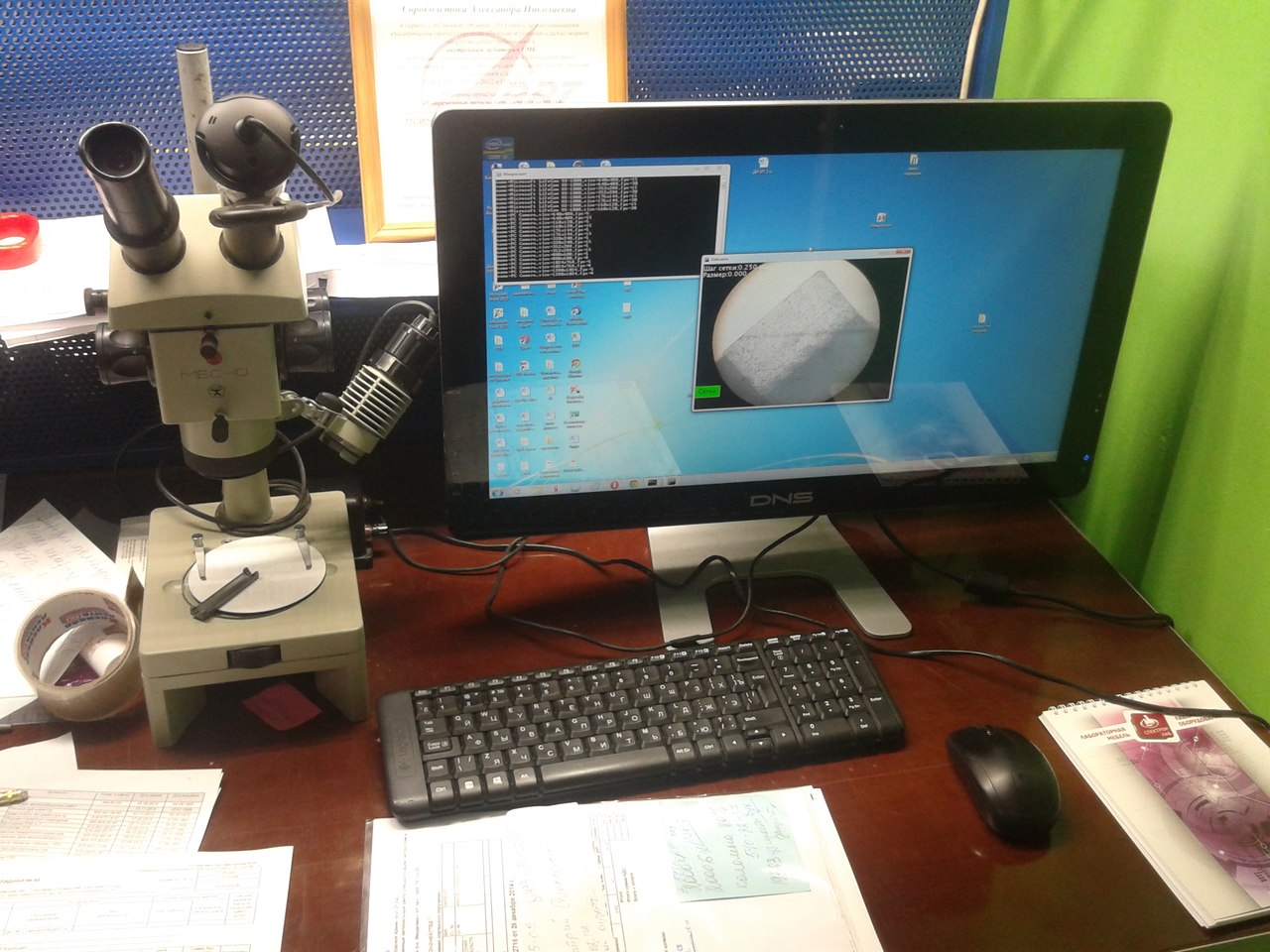
Therefore, I decided to use a ready-made microscope, since it has an optical system and focusing, it remains only with a wide adhesive tape (there was no canonical tape) to wind the camera to the eyepiece. In parallel, the development of software for measuring linear dimensions directly on the screen started. ( Processing is used ) That's my charm, let's see what it sees (unfortunately there was only a camera with a resolution of 640x480).

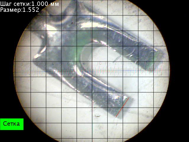
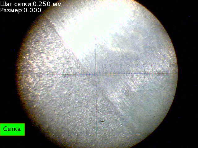
As you can see, clarity, contrast and color scheme are quite perceptible. Here you see the elements of the measuring part (step, size) and the display elements (grid), but first things first.
It is not difficult to get an image on the screen , but it does not provide enough information about the size of the observed object. The first idea was to introduce a measuring grid, that is, put the object down and immediately see its dimensions.
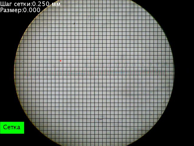
The grid had to be “checked” using a 0.5 mm thick test tile, put it under a microscope and adjust the grid size, it turned out that 0.5 mm is 26 pixels.
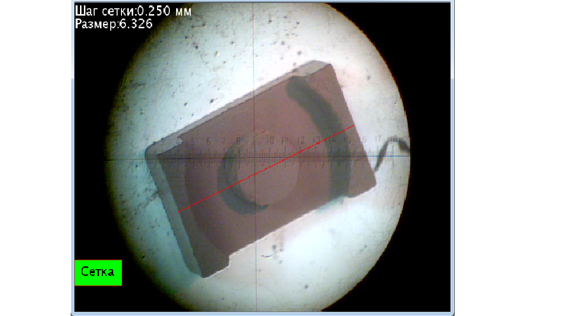
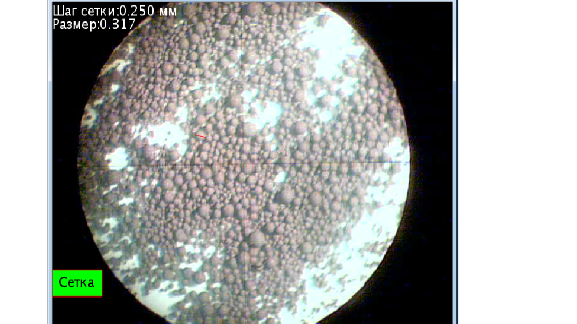
But this is sometimes not very convenient, so a button was introduced to turn on / off the display of the grid. But this is also not enough, because the operator does not always need a fine mesh, so the ability to scale the mesh was introduced. But this is also not enough, because the operator needs to very accurately lay the sample under the grid, performing the work very accurately, this is tiring. The output seemed "direct measurement with the mouse," that is, the operator clicks on the screen in two places and calculates the length of this segment , converted from pixels to millimeters. The accuracy of this method for 20 samples in comparison with an electronic vernier caliper and a micrometer turned out to be about 0.1 mm, which completely satisfied the quality control system.

As a result, everything suited everyone, but there was a little uncomfortable moment - screenshots. Each time, press Alt + PrintScreen, and then save uncomfortable. Therefore, the ability to save a window image with the name of each file by date, for example, Probe12 \ 10 \ 2014.jpg, was screwed on.
This became the final model, which is being exploited.
Finally, a few photos. (Write if you want more) This is a ferrite-glass-metal core coated with titanium by cathodic deposition in a vacuum chamber, the photo shows just the transition boundary of the materials. And this is granular ferrite. Well, actually the code itself . (Minimum comments, if necessary, write) Ready exe (x64, need Java, JRE)

I apologize for the quality of the photo and possible errors in the text.