Belt Sander
Before starting work, I studied in detail the designs of such machines, looked at articles and videos on this topic. At one time, I was thinking about buying, but I decided to make the device myself. The goals were as follows: on the one hand, to get a machine for grinding small parts from soft materials (wood, textolite, plywood); on the other hand, to learn how to develop and design similar products (practical experience in designing).
Development stages
I would single out four stages in my work on this machine:
- Assembly of the first model, prototype. Then I thought that I was making the final version, "the first time." Everything was drawn by hand, assembled - "in place", with a file adjusted. The result was ugly, bulky, uncomfortable in work.
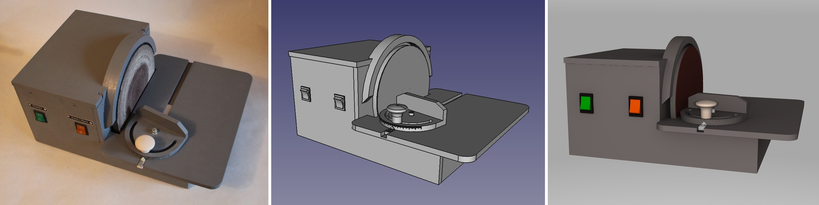
- Refinement and adjustment. The second model. Based on the initial drawings, based on the experience of test operation, with the adjustment of the design, the second version of the machine was assembled. It is presented in the photographs and described in the current review.
- Improvement and modernization. A useful option was completed: angular emphasis. The refinement fell well, fell into place, organically connected with the very body of the machine.
- Creating a parametric model of the machine in a CAD program. In theory, this stage should be the first, but it became the last, since initially there was no understanding and experience in this matter.
Machine Features
- weight: 8.5 kg
- overall dimensions (LxWxH): 460x270x240 mm
- motor power: 180 W (50 Hz, 220 V)
- angular velocity (at the edge of the disk) - 14-15 m / s
- reversing the direction of rotation of the grinding disc
- quick change of the emery wheel on the disk
- fixed table angle (90 degrees)
- possibility of dust removal is realized (inlet diameter - 40 mm)
Angle stop characteristics
- thrust pad length 120 mm
- adjustment range (on a scale) ± 60 degrees

Dolgostroy
It took me about four years of life to complete all stages: the implementation of ideas and ideas, and refinement (I mean calendar years - there were breaks between stages, external circumstances, other projects, etc.).
When I read earlier that personal technical projects can last several years, this surprised me. It seemed to me that why pull so long? He came up with, drew, put it all together in a couple of months - the finish. But, having worked on a new and complex (for me) project on my own, I begin to understand why it happens this way: get distracted by something else, look for a “good” solution, study analogs for a long time, wait for component delivery, design everything in detail (simultaneously mastering new ones) knowledge and technology), etc.
Sometimes, already during the implementation of the current project, ideas come about modernization and improvement, which are obvious, but do not fit into the existing structure. In general, welcome to the field of project management and product release.

Design
The general scheme developed in my head quickly enough. Initially, I did not make drawings (I just ordered an adapter flange on the motor shaft), assembled and customized the parts “in place”. Then already (during improvements and upgrades) - I looked closely at every detail, its shape, location, dimensions, manufacturing methods, installation and replacement. Not all ideas were implemented, but in general - the design is workable and suitable for use.
The cover above the engine is made removable to give access to the internal space: wiring, capacitors, etc. Rubber feet are provided so that the machine does not “travel” around the table during operation. The table is removable, unregulated; has a fixed installation angle of 90 degrees (table tilt relative to the grinding disk is not provided).
The power of the existing engine is completely enough for hobby needs (even with a small margin). Removing on a tree is decent, even if the contact area is large. Of course, if you press the workpiece very strongly against the disk, the rotation of the engine will slow down.
Assembly
I did the assembly with glue - this is a quick and reliable way to connect plywood parts. I used PVA glue (water resistance class - D2). The basis of the steel structure were two bars of 40x50 mm, a support platform for the engine and table fasteners were glued to them. A protective-power frame made of plywood 10 mm thick was attached from above.
Dust removal
Dust extraction is available as an option. I tried to eliminate the cracks in the volume under the desktop as much as possible (so that the dust was sucked out more efficiently). Grinding without dust removal is not very good for the health of the worker and cleanliness in the room. On the side of the case opposite the buttons, under the table, in the case, there is an inlet for connecting a dust extraction system. Through the standard plumbing adapter 40/32, you can connect the hose of a household vacuum cleaner. Tests have shown that with a working dust extraction system it is possible to grind even in an apartment. Almost all small sawdust is absorbed, nothing scatters (the main thing is to choose the direction of rotation of the disk and position the workpiece in the right place).
Grinding disc
Disc diameter: 200 mm. This size was not chosen by chance, it is the width of standard sandpaper in rolls, which is sold in any market. You can buy a piece of any grain and cut the right number of interchangeable disks. The circle itself is made of plywood. It is screwed to the flange with six M6 bolts. After installation, the circle is chiselled in place (to ensure flatness). The grinding speed (at the edge of the disk) is obtained in the region of 14-15 m./s. which is enough for woodwork. The emery wheel is fixed on a double-sided tape. I tried to change sandpaper - this is done easily and quickly, the mount is strong.
Electrician
No “collective farm” and twisting: all electrical connections are made on terminals, clamps or soldering. The correct scheme for reversing a single-phase motor has been implemented (and not through changing the working and starting windings, as shown in one video on YouTube). I bring a circuit diagram of an electrician connecting an engine.

Painting
Regarding painting and putty, I studied the experience of those craftsmen who restore metal machines (but there they are mainly used for epoxy putty). I did not have a utility room for work - I chose a paint that can be painted in a living room, safe from an environmental point of view. He stopped at a water-based acrylic paint. The pigment was selected and mixed separately (the paint was originally white).
If I had a workshop, I would now more responsibly approach the processing and painting of the case: I would fill all the cracks and defects of the plywood with putty, I would grind it more and more carefully, paint it in several layers. If you apply several layers of putty or paint (with intermediate sanding and sealing all the roughnesses and imperfections of plywood) - we get a very flat and smooth surface. With due diligence, you may not even understand what kind of material it is (it will look like plastic, metal).
Angular emphasis
The last step was the angular emphasis for the machine. This is my first emphasis (which I made and used in my work). Prior to that, everything was sharpened “by eye”, but the result was, to put it mildly, not very. Work without emphasis, conductor or guides - get a mediocre and unpredictable output.

The accuracy of the “scale” of course does not reach the factory, but it is possible to set the angle in advance - and then, the adjustment and more accurate measurements, corrections. I also recommend moving the axis of rotation of the stop as close as possible to the thrust pad. This is not obvious during the construction, but it is clear during operation.
He began to focus “from scratch”, not knowing at all what it is and how it will have to be exploited. At first, there was a lack of understanding of how long the thrust pad should be. Therefore, I made two blanks: 100 and 120 mm. Stopped at a length of 120 mm. Now I would have additionally provided holes for fixing external devices.
Parts for assembling a draft version of the stop, the handle is made of furniture fittings, an aluminum strip was bought for the guide (a little wider than necessary). The reason for the duplication of holes - I could not drill a perpendicular hole the first time (everything was going crookedly).

In the machine table, we mill a groove under the guide. A reinforcing strip of plywood is glued below. Guide height - 6 mm, groove depth - 7 mm, plywood 10 mm thick.
Initially (in one installation, in one pass of the milling cutter) we get a groove of the same width along the entire length of the table. If you make several passes, the groove will be of different widths at the beginning and end (I didn’t think of how to make it the same width with the available tools and skills). The guide is shorter in length, and can be adjusted to the groove in width without any difficulties.

Ideally, we get a smooth course of the angular emphasis (without backlash) along the entire length of the table.
In reality, of course, there will be small gaps (due to careless execution, technology errors and shortcomings, etc.).
Close-up. Visible are numerous hand-made flaws. In the future, it would be nice to engrave (apply with a laser) them directly on the stop or make the scale a separate part and install it on the product.

I tested the angular emphasis a bit: I tried to grind the cubes, as well as make a connection at 45 degrees. The cubes did not work out (there was little time and you need to make a device for grinding the edges at 45 degrees (with exposure in three planes))
But the connection like "frame for a picture" surprisingly turned out to be quite accurate. The planes fit perfectly together and form an angle very close to ninety degrees.

Disadvantages, errors:
- the design turned out to be partially non-separable (the engine cannot be replaced without dismantling the housing part)
- chose the wrong motor with a time limit for continuous operation and rotor imbalance
- even though the grinding disc itself is partially balanced, but during operation there are slight vibrations in the machine (due to the engine).
- Now I would redo the electrical circuit of the machine: I would add a large “Stop” button, I would connect the motor not directly, but through a relay (starter). Those. connection would be made as with "adult" machines.
Advantages, advantages:
- dust extraction system works very well
- the presence of auxiliary devices (angular emphasis, other additions in the future)
- light weight, compact design
- low price (if you count only materials and external work)
Creating a parametric model
The last stage of work for me was the creation of a parametric model of the machine in a CAD program.

Drawing in various versions of paper and electronic pockets is already in the past. Similar concepts come from the 80s. Now it’s much more efficient to model a parametrized solid, and to remove views and sections from it. Such an approach is not a substitute for drawings, it is conceptually different. The resulting models can be directly transferred to CAM for production (cutting, milling, 3D printing, etc.).
It was very difficult for me to mentally switch from the development concept “ I thought, figured everything out in my head and drew paper / electronic drawings , transferred to production ” to “ thought, created a solid model, corrected errors and inaccuracies, created drawingshanded them over to production . ” It took a lot of effort (to change stereotypes), you always want to go the "easy" and familiar way. I remember that on several forums I read the statements of more experienced comrades about which methods of work are most effective, but I missed it; or could not understand; or understood, but did not have the time and energy to acquire new skills.
In this project, I chose the program FreeCAD. There are a lot of lessons and a training video on it. Of course, there are many more complex and professional development packages, but the available functionality for my level and range of tasks was enough. Even the rendering (visualization) of the model was able to be set up and run (although initially I wanted to study Blender 3D for this).
After the stage of getting used to the interface, working with model parameters and assembling all the parts together is fun and allows you to fully concentrate on development, seeing the whole picture.
I remember how I tried to hold and correlate “in my head” several interdependent sizes, transfer them to the drawings. And still, after long titanic efforts, he was mistaken and re-ordered the manufacture of individual parts in the assembly.

Conclusions and Conclusion
When practice and theory go side by side, in the presence of interest and determination, one can master almost any area of human activity and solve a complex complex problem.