We program the GSM module M680 OpenCPU

It is probably no secret that some GSM-modules support downloading applications and can work without an external control controller. I want to talk about small experiments with one such module - Neoway M680 OpenCPU .
The ability to download applications directly to the module is good because it allows you to reduce the size and cost of the device. This is not always the best solution, but in some cases it can be really useful. By the way, the size of the M680 OpenCPU itself is 1.5 by 1.8 cm, so the device can be really small.
Available interfaces: UART - 2 units, SPI or I2C, ADC - 3 units, GPIO - 15 units, USB 1.0, PCM, analog microphone inputs - 2 units, analog audio outputs - 3 units.
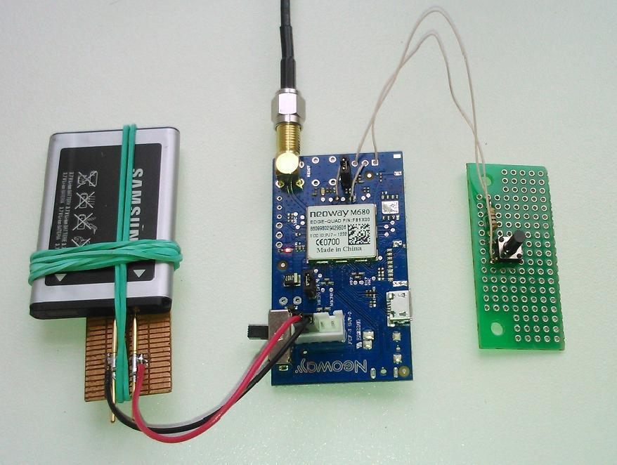
In general, I decided to try to connect a button directly to the GSM module and, when pressed, perform a simple action - call somewhere or send an SMS. I soldered the button to the module’s small debug board, which already has a SIM card holder, power connectors, and antennas to save time. Food - from the cell phone battery.
The result is this model:
The module documentation and OpenCPU can be found here: Neoway M680 OpenCPU
You can get examples of working with the module from the ETF that help a lot when starting.
The module is controlled by AT commands from the application through a virtual UART. To call a phone number, you need to send only one command to the virtual UART: ATD + 7xxxxxxxxxx ;, where + 7xxxxxxxxxx is the desired number. Therefore, making a call on an event is probably one of the simplest applications.
A simple program that calls the specified number when you click on the button looks like this:
/*****************************************************************************
 * Interrupt pin 40 - make a call to phone number +7xxxxxxxxxx
 *****************************************************************************/
#ifdef __EXAMPLE_HELLOWORLD__
#include "neoway_openplatform.h"
U8 AT_MAKE_CALL[] = "ATD+7xxxxxxxxxx;\r";	// AT-команда совершения звонка на номер +7xxxxxxxxxx
void Neoway_UserInit(void)
{
	Neoway_StopWatchdog();	//Остановить watchdog
	Neoway_InterruptInit(44,NEOWAY_INT_10);                   //Установить GPIO 44 (pin 40) как прерывание 10
	Neoway_InterruptSetDebounceTime(NEOWAY_INT_10,40);		  //Установить  время дребезга контактов (40 тиков)
	Neoway_InterruptSetPolarity(NEOWAY_INT_10,NEOWAY_TRUE);    //Установить полярность сигнала – высокий уровень или передний фронт
	Neoway_InterruptSetTriggerMode(NEOWAY_INT_10,NEOWAY_FALSE); //Прерывание по уровню сигнала
}
void Neoway_UserTask1(NeowayMsgTypeStruct msg_type,NeowayModuleTypeEnum mod_type)
{
	switch(msg_type.msg_id)
	{
		case NEOWAY_MSG_ID_INT_NOTIFY10:
				Neoway_VirtualUartSend(NEOWAY_MOD_USER1, AT_MAKE_CALL, strlen(AT_MAKE_CALL));	// Позвонить на наш номер
			break;
		default :
			break;
	}
}
void Neoway_IntResponse(NeowayIntNumEnum int_no,NeowayModuleTypeEnum mod_id)
{
	if(int_no==NEOWAY_INT_10)
	{
		Neoway_SendMsgTask(mod_id,NEOWAY_MOD_USER1,NEOWAY_MSG_ID_INT_NOTIFY10,NULL,0); // В качестве реакции на полученное прерывание послать сообщение NEOWAY_MSG_ID_INT_NOTIFY10 в task1
	}
}
void Neoway_RegisterCallbackFunction(void)
{
	Neoway_RegisterCallBack(NEOWAY_KB_ID_USER_TASK_1,(U32)Neoway_UserTask1);	//Регистрация функции Neoway_UserTask1
	Neoway_RegisterCallBack(NEOWAY_KB_ID_INT_RESPONSE,(U32)Neoway_IntResponse);	//Регистрация функции Neoway_IntResponse
}
#endif
GPIO 44, pin 40 is used as the interrupt input. The interrupt input through the button is connected to the VDD_EXT pin 36. When the button is closed, the Neoway_IntResponse function is called, which sends a message to Neoway_UserTask1, and this, in turn, initiates a call to a predetermined number.
Of course, in this simple program there are no checks, etc., but, nevertheless, it works fine.
If replaced:
U8 AT_MAKE_CALL[] = "ATD+7xxxxxxxxxx;\r";on the
U8 AT_SMS_TEXT_MODE[] = "AT+CMGF=1\r";
U8 AT_SEND_SMS[] = "AT+CMGS=\"+7xxxxxxxxxx\"\r";
U8 AT_MESSAGE[] = "Hello_HABR!\x1A";
and
Neoway_VirtualUartSend(NEOWAY_MOD_USER1, AT_MAKE_CALL, strlen(AT_MAKE_CALL));on the
Neoway_VirtualUartSend(NEOWAY_MOD_USER1, AT_SMS_TEXT_MODE, strlen(AT_SMS_TEXT_MODE));
Neoway_VirtualUartSend(NEOWAY_MOD_USER1, AT_SEND_SMS, strlen(AT_SEND_SMS));
Neoway_VirtualUartSend(NEOWAY_MOD_USER1, AT_MESSAGE, strlen(AT_MESSAGE));
then when the button is pressed, the module will send an SMS “Hello_HABR!” to the number + 7xxxxxxxxxx.
As a compiler, I used RVDS, taken on one of the torrents.
To compile, run the cmd.bat file from the example folder, upon successful completion, among other things, the inscription appears:
****************************** **************************
Done
The target image is in the 'build' directory.
***************************************************** *****
firmware files appear in the build folder.
If something went wrong - build.log from the same folder helps.
To load the application into the module via UART, the FlashTool program is used:

The loading procedure is as follows:
1. Run FlashTool, set the COM port, speed.
2. Click the Download Agent button and select the MTK_AllInOne_DA.bin file from the program folder.
3. Press the Scatter / Config File button and select the NEOWAY60S_MOD_11B_BB.cfg file from the build folder.
4. Remove the daw PRIMARY_MAUI, leave only the daw ROM1.
5. Click the Download button and then turn on the power to the module.
6. If the download is successful, the “OK” window appears with a green circle - after that you can restart the module and test the result.
I hope someone comes in handy, thanks for watching!









