Kinder surprise dc motor
- From the sandbox
- Tutorial
Introduction
My name is Konstantin and I am a student of Novosibirsk State Technical University. It so happened that I was studying to be a physicist, but the theoretician was not so hot out of me, so theories in my publications will be very few or even completely absent.
As the name implies, we will collect a DC motor with you.
I had a book in my childhood where there was an instruction on how to make it out of a box of matches, straws and 2 magnets, but we won’t do this, nor will we do something like this:
Motors in 10 minutes

I think that what I show will not be new, but a quick Google search gave only the results that are higher, so let's get started, but for those who don’t know what they’re talking about: DC motor
I got this kind of thing:
Cooking
First we decide what we need (I used everything I could find in the room, so don’t really kick):
- A plastic case from the kinder, and I found one that opens across.
- 2 small magnets that are easy to place inside. I used neodymium 5x8x8mm, 35p piece.
- A wire, nail or stick with a cross section of 1-1.5 mm as an axis. I found a tube of a similar diameter, at first I wanted a cotton swab, but it turned out to be thick and soft.
- Glue. I used cyanocrylate and hot melt.
- Collector winding wire. I took it from the headphones, it is immediately varnished and without insulation.
Wire, plates, or other magnets or pheromagnets as a core. I took 30mm nails.- Brain, hands and good neighbors. if in a hostel like me.
The list is not complete, the rest is trifle and interchangeable.
Assembly
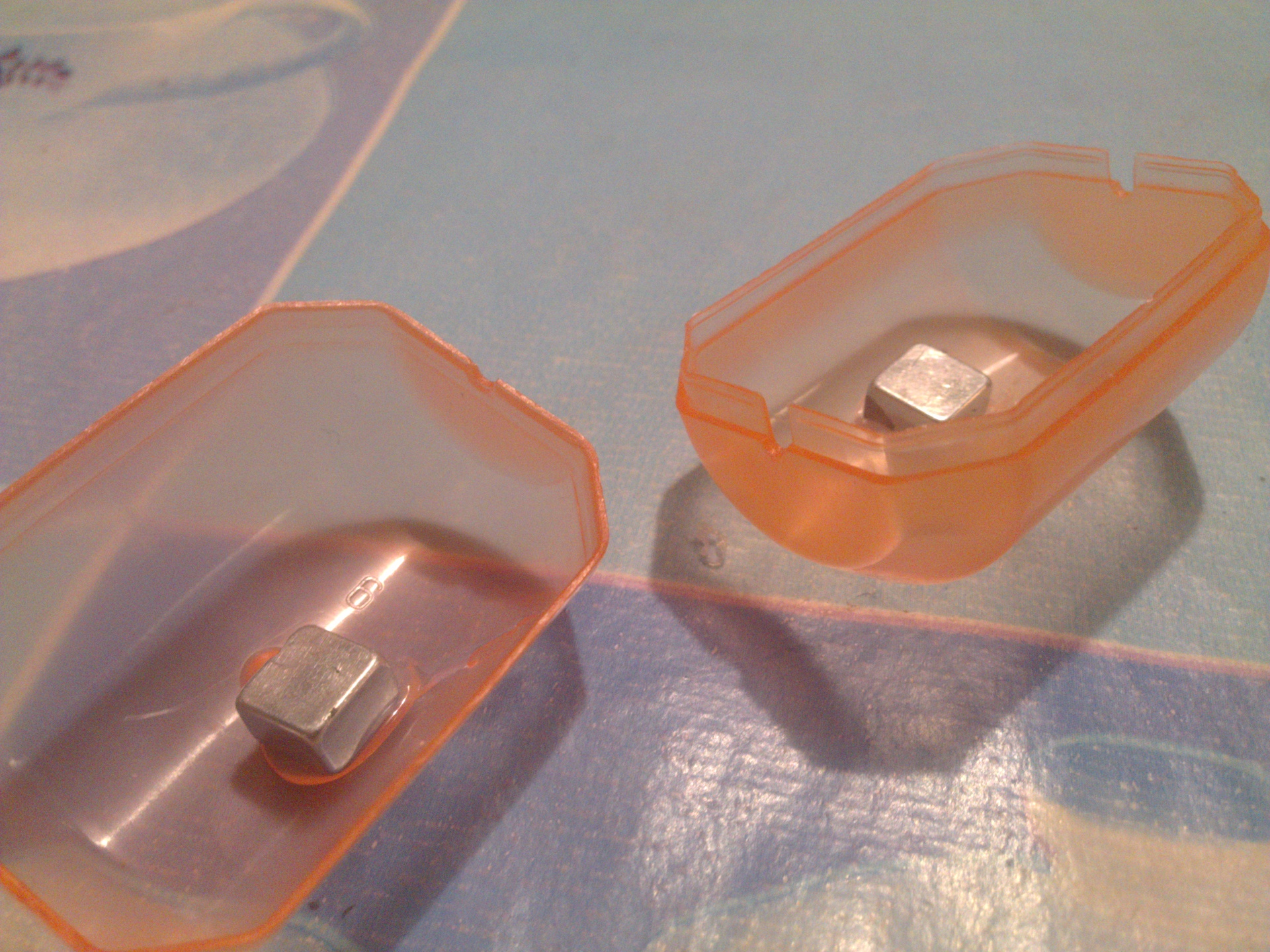
At first, I glued the magnets to the case, since the pipes were at the bottom of the halves, I shifted them. I glued it with hot glue, but since they are very strong, after n closing / opening the case, they got out (I even coated it around - it didn’t help), and I poured superglue to the bottom.
Magnet Installation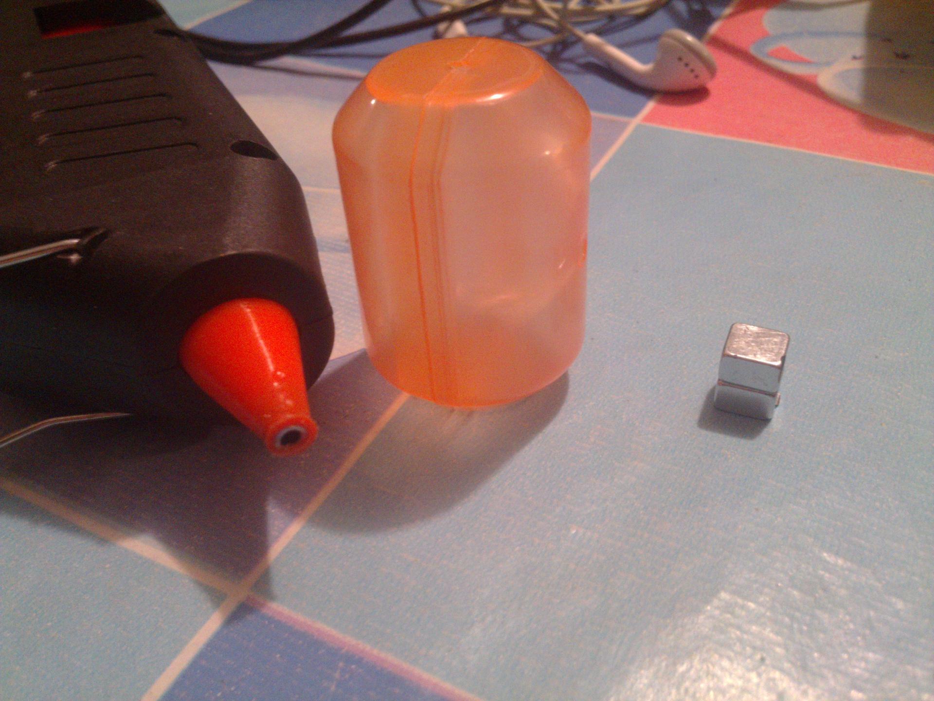
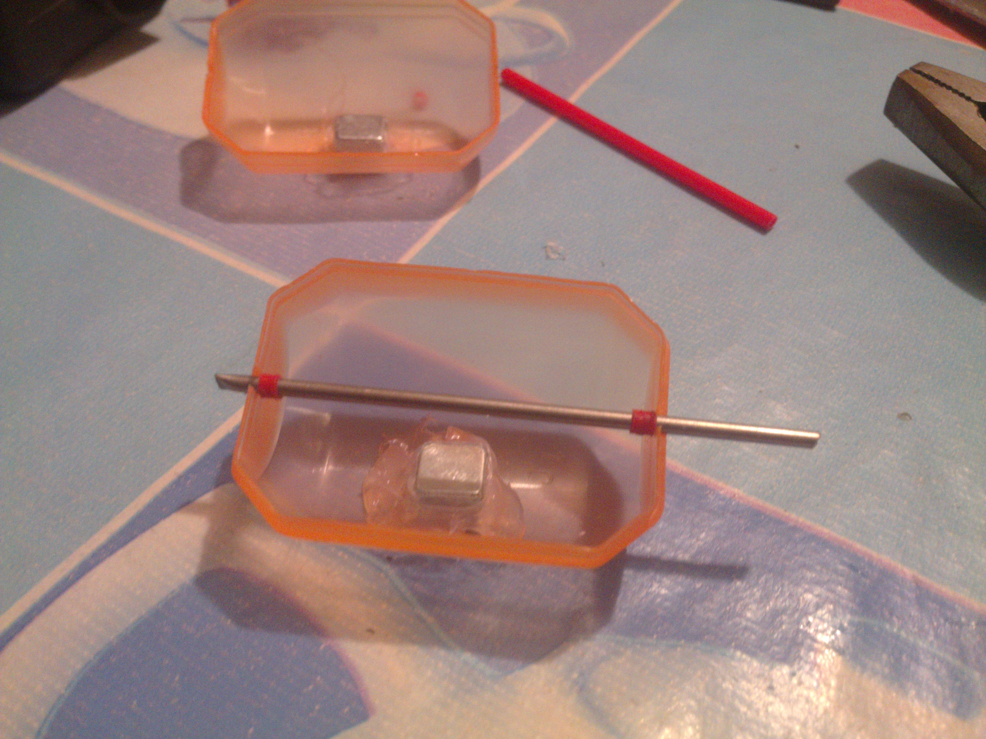
Next you need an axis. I took a steel pipe (I don’t know what it was from, I found it in a box) and put on it stop rings from a cotton swab, the holes were already in the case itself and the axis fit perfectly. It turned out pretty nice:
Make axis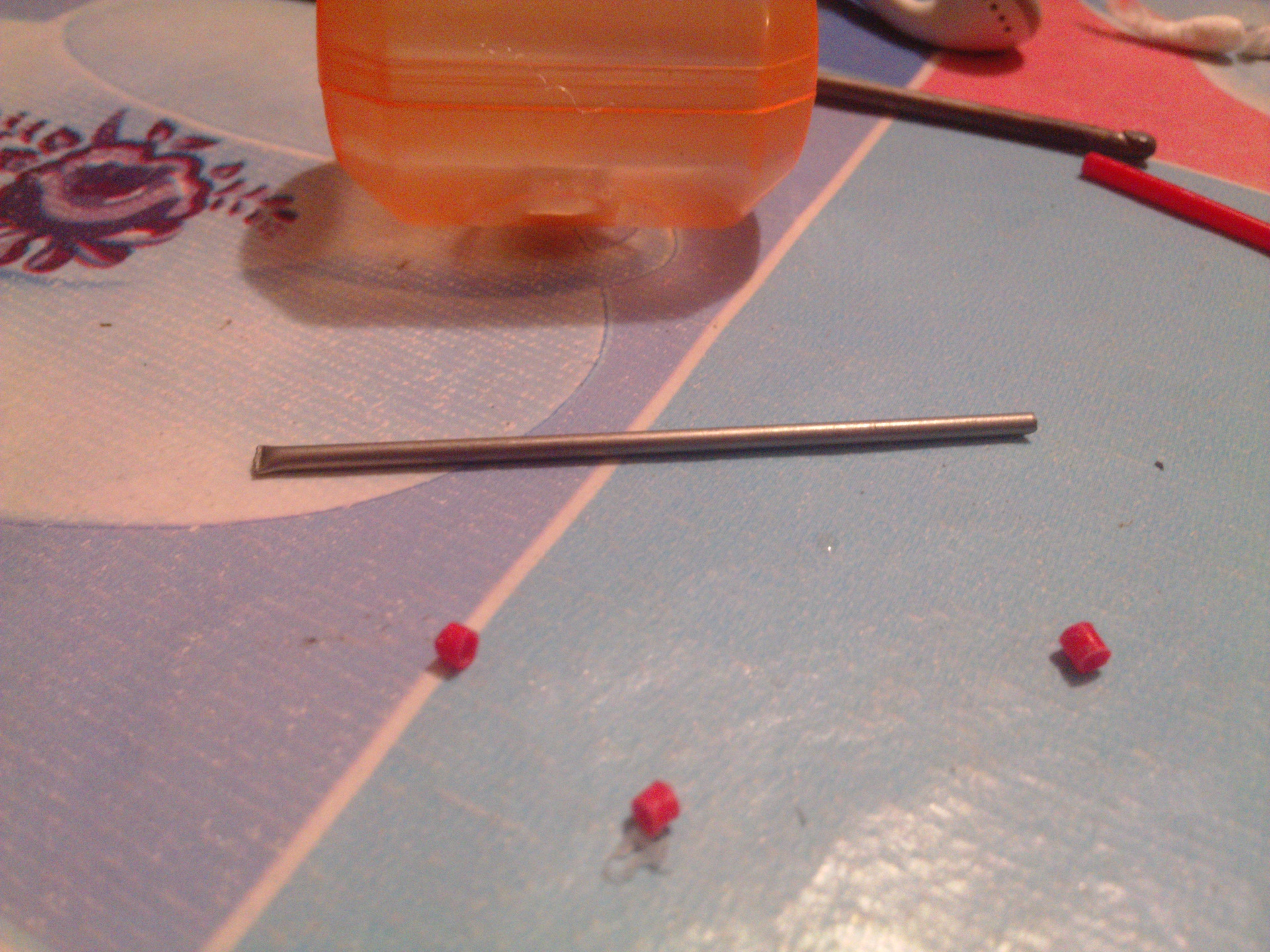
It all takes no more than 5 minutes, the fun begins with the manufacture of the rotor. There were as many as 3 rotor options: a non-magnetic core, steel, steel with a wire of 0.5 mm. For the first, I took a stick from ikea and made 2 pieces of 2 cm each. In the center of them I cut grooves under the axis so that it would go in tightly and then glued it together. Do you think this design fit and rotated? No, it turned out that the magnets stood a little at different heights, and the pieces themselves were longish. For about 20 minutes I had to adjust a piece of grindstone so that the rotor would not touch the magnets. Its winding was carried out from a cable of headphones, I don’t know exactly how such wires are called. The winding itself in the original version consisted of 24 turns in 2 layers - how much wire was enough.
The trouble with this type of electromagnet is a small inductance, and consequently a small magnetic field. I realized this when I tried to measure the tension of such a rotor.
Initial rotor


I made the second version of the rotor from carnations - 2 rows of 4 pieces in a checkerboard pattern. I connected them with hot-melt glue, it turned out something in the form of chokopayka, only instead of souffle - hot-melt glue. This rotor had the same problem as the first one - no matter how I measured it, it touched the magnets. The same grinding disc helped, only it took longer to grind the edges. The winding was carried out with the same wire, and the wire from the twisted pair was 0.5 mm copper, though I wound 0.5 mm of wire only 1 row of 6 turns per shoulder, since it was thicker and smaller.
Nail Tiles
It was a bad idea. Since I had rather strong magnets, and the gap between the magnet and the core was about or less than 1 mm: the rotor could not be rotated by the shaft - the shaft was spinning, and the rotor remained between the magnets. Since I couldn’t even manually rotate the steel rotor, my electromagnets couldn’t push the magnetic field between the magnets with my own field, and when the power was connected (such a polarity that magnetic induction was the opposite direction between the poles of the magnets) they would start to heat up very much (if mine theory is not correct, correct).
So the decision was to stay on the rotor of the first type, without magnetically conductive material, but with an increased number of turns 2 times (winding is crooked, since I fastened the ends with superglue, and the winding sprinkled on the droplets, and then I just scored it for evenness).
Old is once again in fashion
To test for operability, I stuffed this rotor into the housing, hooking it to the wires. When connected to the battery, he turned and stood perpendicular to the axis of the magnets.
Current collectors
According to the motor circuit, we need to make current collector contacts.
I decided not to bother with this, took 0.5mm wire from the former failed rotor, bent it several times and glued it to the tube and the rotor itself perpendicularly, as in the picture. Then he cleaned it all with the same grindstone and soldered the rotor coil leads. It turned out pretty.
Current collector rotor
Everything is good, that's all, it remains only to make brushes to bring the current to the current collectors, but I decided not to think hard, and tried to do as in the picture: I

just threw one wire under the current collector, stripped at the point of contact, and one above it, and clamped the edges of the body. It seems that the idea is good, but if you pull it hard, it slows down the shaft.
Motor assembly
Start
I collected it, picked up the battery and ... nothing, I decided to turn the shaft - it’s a little tight. I relaxed a little wire-brush, picked it up again - nothing, just some squeak in certain positions, if you turn the shaft by hand, and the slip of the rotor when it is next to the magnet.
Then I decided to honestly do: I balanced the rotor so that the beats became minimal, smeared the shaft with lithol in the places of contact and made normal brushes. After that, he earned, but not without problems, he still had to be powered by + 5v 1A, as ftp27 advised , in the same way, as radiolok wrote , then such a motor has dead zones, or rather one - when the rotor is across the axis of the magnets, because of this I had to start the motor manually, turning it a bit (in my design, the angle when the brushes do not touch, more because of the big inaccuracy in manufacturing brushes and current collectors).
File Editing

Thank you for reading my post, it’s finished on this, but if you are hunting, I can try to check some characteristics, such as: rotation speed, torque, and maybe something else.
Only registered users can participate in the survey. Please come in.
To study the characteristics?
- 76.3% Yes 71
- 23.6% No 22