Unreal Engine4 - PostProcess scan effect
- Transfer
- Tutorial
This weekend I had some free time between classes (note, the author at the time of the article received a Master of Science degree) , and I decided to go back to creating shaders, inventing this postprocess scan effect. I imagined that it was used in the game as a sort of scanning effect at a distance. We also use some simple noise distortion to make the effect look a bit more interesting.
In this article I will explain how to implement this effect on UE4. There are several ways you can create this effect. One of these methods was chosen by me.
You can open the images in a new tab to view them in higher resolution.
Main components
The main idea of this effect is to create a version of the scene render using the Sobel operator , and then mix it with the usual scene render based on SphereMask, which we will animate to create a scanning effect.
This effect consists of 3 main components:
- SphereMask scalable field
- The Sobel-Edge function (I will not explain how this function works, since it is a separate topic, but I will refer to the code that I used)
- Overlaying the projected texture onto the mesh of the world
SphereMask scalable field
This part is about how we create a scalable SphereMask. To do this, we transfer the position of the blueprint to the material parameter set, and then use it as follows.

Connect the result of the Clamp node to the emissive output of your material, and you will see something like this

“TexLoc” is vector3 , which defines the location of the source of the sphere, In my case, it is read from the set of material parameters, so that it can be read from the game itself, for example, to determine the position of the player.
The set of node parameters specified above creates a field with a sphere radius of 1024 units. I used it only to show the result in the preview window. If you want to learn in more detail how to work with remote functions and understand the methods of using them, I strongly recommend checking out the Inigo Quilez website .
Now we will use Time to scale the sphere with a set period of time.

This will give us the following result:

Frac (time) basically gives us a constant period, which continues to go 0-1.0-1.0-1. We multiply the time by 0.25 to control the speed of scaling, and then multiply the result by the radius of the sphere, which leads to a change in radius from 0 to 1024, and gives us an animated mask.
This is a good result, but it is not what we want from the effect. We need a scaling ring. This can be easily done with simple calculations.

This will give us what we want, a growing ring, with good gradient damping that can be controlled.

Mathematical operations in the "Edge_Mask" block basically choose the position in the gradient mask, in this case the value 0.5, and determine the edge of the mask from the current position with a given width, which allows us to get a ring. I will not go into technical details getting the edges of the mask, most likely I will tell about it in one of the following posts.
As you can see, you have full control over the width of the ring without a scalar parameter, and if we wanted, we could even control the edge attenuation, but in this effect we do not need it.
The next step is to use noise to create a visually interesting version of the ring.
To do this, we will use the Vector Noise node , which is part of UE4. You can read about it here , or you can use the noise texture, which contains World Aligned UV coordinates.
In my shader I installed in the node Vector Noise parameter Function in Cellnoise , feel free to experiment with other types of parameters to get your own unique effect.

The result will look like this
. This completes the first stage of our shader, then we will consider the implementation of the Sobel-Edge function.
Sobel-edge function
There are many different variations of this feature, some of which are more optimized than others, I will not explain its essence, since this is a separate topic, but a simple Google search for the keywords "Sobel Edge" or "Sobel Operator" will give you many options . Or use the article on Habré from Gepard_vvk - Algorithms for image contour selection .
The main idea of the operator Sobel is as follows: we take RenderTargetscene (imagine that this is a texture that contains what you currently see in your viewport) and compare each pixel with all adjacent pixels around it. Next, we compare the difference in brightness, and if the difference is above a certain threshold, we mark it as an edge, and in this process we get a black and white RenderTarget texture mask , in which the mask is adjusted to the edges.
The code below is a simple example of the function of the Sobel operator that RebelMoogle created on Shadertoy (most likely this option is not fully optimized, so you can try another implementation), we will recreate it in UE4 in our material.
void mainImage( out vec4 fragColor, in vec2 fragCoord )
{
    vec2 uv = fragCoord.xy / iResolution.xy;
    vec3 TL = texture(iChannel0, uv + vec2(-1, 1)/ iResolution.xy).rgb;
    vec3 TM = texture(iChannel0, uv + vec2(0, 1)/ iResolution.xy).rgb;
    vec3 TR = texture(iChannel0, uv + vec2(1, 1)/ iResolution.xy).rgb;
    vec3 ML = texture(iChannel0, uv + vec2(-1, 0)/ iResolution.xy).rgb;
    vec3 MR = texture(iChannel0, uv + vec2(1, 0)/ iResolution.xy).rgb;
    vec3 BL = texture(iChannel0, uv + vec2(-1, -1)/ iResolution.xy).rgb;
    vec3 BM = texture(iChannel0, uv + vec2(0, -1)/ iResolution.xy).rgb;
    vec3 BR = texture(iChannel0, uv + vec2(1, -1)/ iResolution.xy).rgb;
    vec3 GradX = -TL + TR - 2.0 * ML + 2.0 * MR - BL + BR;
    vec3 GradY = TL + 2.0 * TM + TR - BL - 2.0 * BM - BR;
    fragColor.r = length(vec2(GradX.r, GradY.r));
    fragColor.g = length(vec2(GradX.g, GradY.g));
    fragColor.b = length(vec2(GradX.b, GradY.b));
}
The UE4 it looks like this
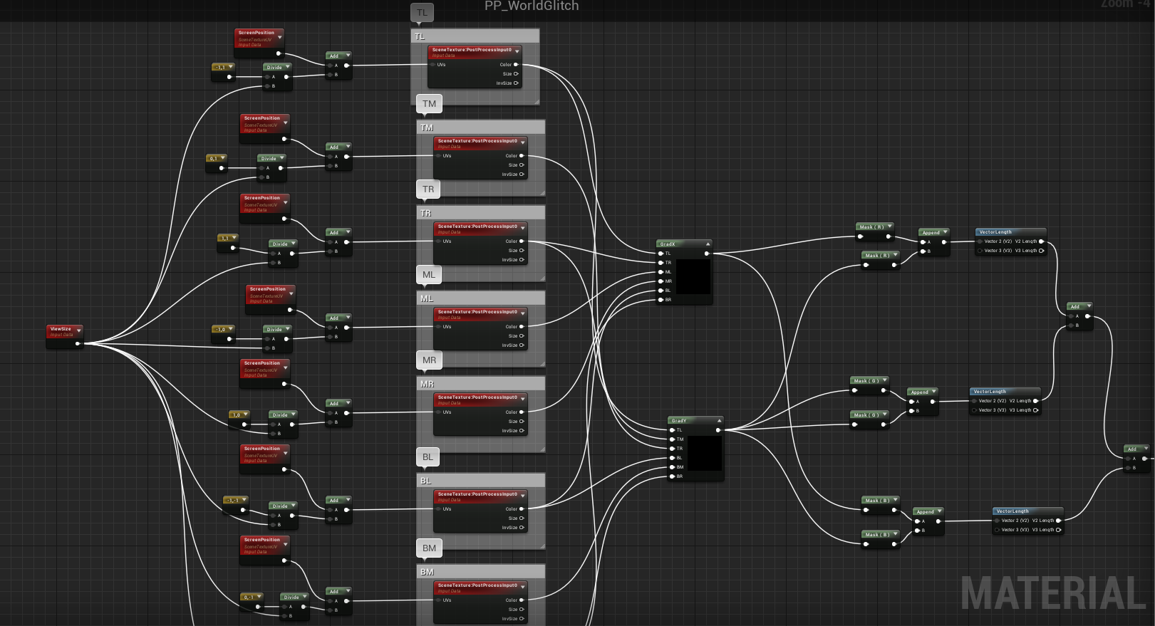
small note on the implementation of the function - make sure your node SceneTexture configured to use PostProcessInput0

Two Custom node GradX and GRADY , configure them likewise

GradX :
return -TL + TR - 2.0 * ML + 2.0 * MR - BL + BR;GradY :
return TL + 2.0 * TM + TR - BL - 2.0 * BM - BR;This does not have to be done in Custom , I used it just for convenience, because otherwise there would be too many nodes and spaghetti is formed.
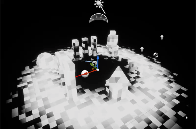
If you connect the result of the function to the emissive material output, you will see the following.

Also, we multiply the result by the usual vector3 to make the edges of any color we want.

As a result, the edge color changes.

Texture overlay world mesh
The simplest part: we just use the grid texture and project it around the world, and then combine it with the Sobel-Edge function to get a cool effect.
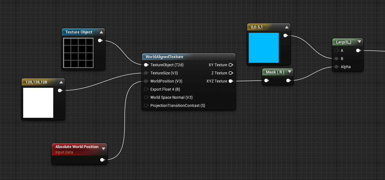
If you connect the result of the function to the emissive output, you will see

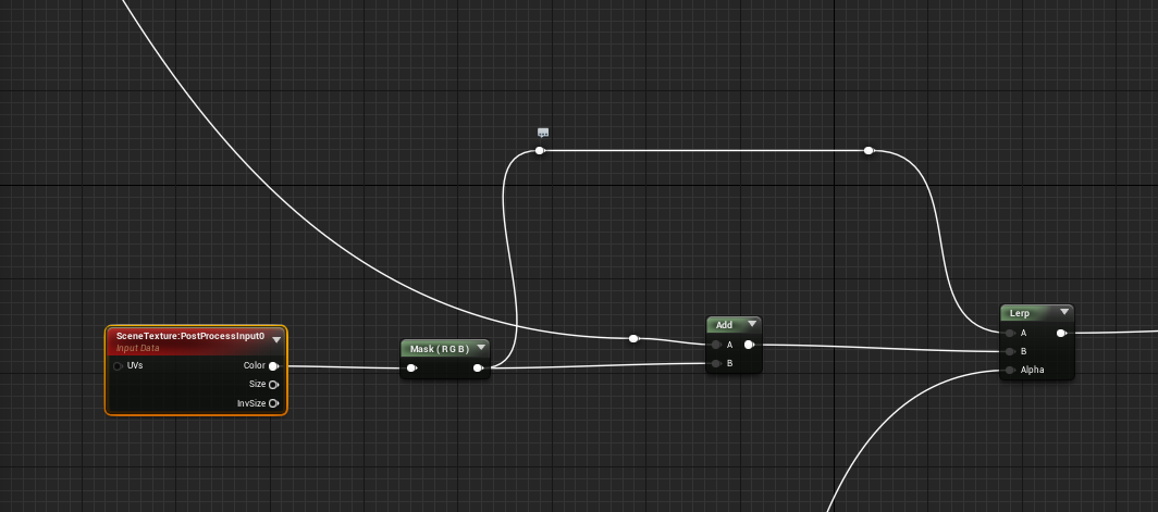
Putting it all together
Now we will put all three parts together for our post effect!
First, we combine the Sobel-Edge and World-Aligned-Grid function, adding them together.

Then we create the SceneTexture node and add the result from Sobel-Edge and World-Aligned-Grid to it.
Then we interpolate between the normal scene and the added one, using the result of the ring mask we created in the first part.
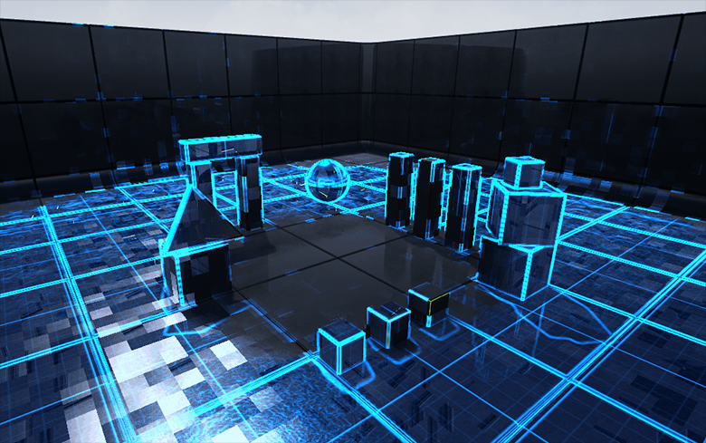
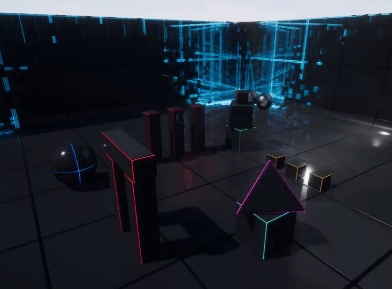
And voila, we did it. The final result will look something like this. You can, of course, adjust the parameters and try changing their values to get more interesting options.
I hope you find this information useful, all the best :)
You can find an example of a project with this shader on github .