Learn OpenGL. Lesson 4.1 - Depth Test
- Transfer
- Tutorial

Depth buffer
In the lesson on coordinate systems , we rendered a three-dimensional container using a depth buffer, which prevented the erroneous display of faces behind others. In this lesson, we will take a closer look at the depth buffer (or z-buffer) and the values stored in it, and also find out how exactly the check passes if the fragment is behind the others.
Content
Part 1. Getting Started
Part 2. Basic lighting
Part 3. Download 3D models
Part 4. Advanced OpenGL Features
Part 5. Advanced Lighting
Part 6. PBR
- Opengl
- Window creation
- Hello window
- Hello triangle
- Shaders
- Textures
- Transformations
- Coordinate systems
- Camera
Part 2. Basic lighting
Part 3. Download 3D models
Part 4. Advanced OpenGL Features
- Depth test
- Stencil test
- Color mixing
- Clipping faces
- Frame buffer
- Cubic cards
- Advanced data handling
- Advanced GLSL
- Geometric shader
- Instancing
- Smoothing
Part 5. Advanced Lighting
- Advanced lighting. Blinn-Fong model.
- Gamma correction
- Shadow cards
- Omnidirectional shadow maps
- Normal mapping
- Parallax mapping
- HDR
- Bloom
- Deferred rendering
- SSAO
Part 6. PBR
The depth buffer, as well as the color buffer (which stores the colors of all fragments - a visible image), stores certain information for each fragment and, usually, has the same sizes as the color buffer. The depth buffer is automatically created by the OS window system and stores the values in the form of 16, 24 or 32 bit floating point numbers. On most systems, a buffer with a precision of 24 bits is created by default.
When the depth test is enabled, OpenGL checks the depth of each processed fragment against the data stored in the buffer. When passing the test, the contents of the buffer will be updated with the depth value of the processed fragment, if the test fails, the stored value will remain the same, and the fragment is discarded.
The depth test is performed in the screen space after performing the fragment shader (and after the stencil test, which will be discussed in the next lesson). The screen coordinates are directly related to the parameters of the viewport specified by the glViewport function , and are accessible through the GLSL built-in variable gl_FragCoord in the fragment shader code. The x and y components of this variable are the coordinates of the fragment in the view window (the lower left corner of the window has coordinates (0, 0)). At gl_FragCoord also has a third component, which actually contains the value fragment depth. This z-component is used to compare with values from the depth buffer.
Modern GPUs almost all use a trick called an early depth test. This technique allows you to perform a depth test before running a fragment shader. If we become aware that this fragment cannot be seen in any way (blocked by other objects), then we can discard it until the shading stage.
Fragment shaders are rather computationally heavy, so you should avoid executing them where it makes no sense. This technique has only one limitation: the fragment shader should not change the value of the fragment depth. This is obvious, because OpenGL in this case will not be able to determine the depth value of the processed fragment in advance.
The depth test is disabled by default. Turn it on:
glEnable(GL_DEPTH_TEST); Now, with the depth test turned on, OpenGL will automatically save the depth values for all fragments that passed the test and discard those that didn't pass.
Enabling the depth test also requires clearing the buffer from the old values in each frame. A new flag GL_DEPTH_BUFFER_BIT is added to the familiar glClear function
glClear(GL_COLOR_BUFFER_BIT | GL_DEPTH_BUFFER_BIT); In certain situations, you may need to perform a depth test for processed fragments with discarding them according to the test results, but without updating the contents of the buffer itself. Those. Assignment to the read-only mode buffer. Writing to the buffer is disabled by setting the depth mask to GL_FALSE :
glDepthMask(GL_FALSE);I note that this only makes sense when the depth test is on.
Depth Test Function
OpenGL allows you to override the comparison operator used in the depth test, which gives us fine control over which fragments are worth processing, which ones to discard and in which cases the depth buffer will be updated. The operator is set by calling the glDepthFunc function :
glDepthFunc(GL_LESS); The function accepts the identifier of the comparison operator from this list:
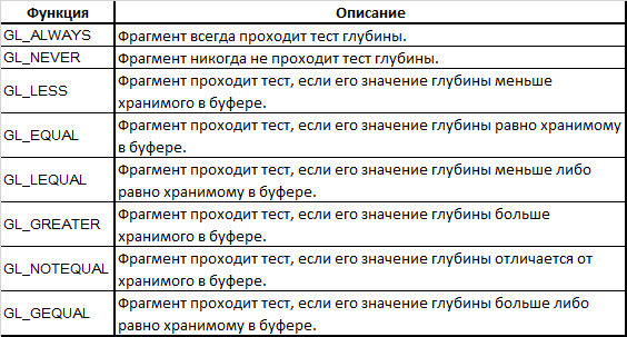
By default, GL_LESS is used , which means discarding all fragments that have a depth greater than or equal to the depth value stored in the buffer.
Let's experiment with how different comparison operators affect the output of our application. We are using a new project that sets the scene with two textured cubes standing on the floor and not using lighting. The source code is here . First, change the operator to GL_ALWAYS :
glEnable(GL_DEPTH_TEST);
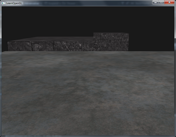
glDepthFunc(GL_ALWAYS);This setting is equivalent to turning off the depth test, which in the end simply displays fragments processed later on top of those that were processed earlier, even if they should have been in the foreground. And since we draw the floor last, its fragments overlapped all previously displayed fragments of cubes:
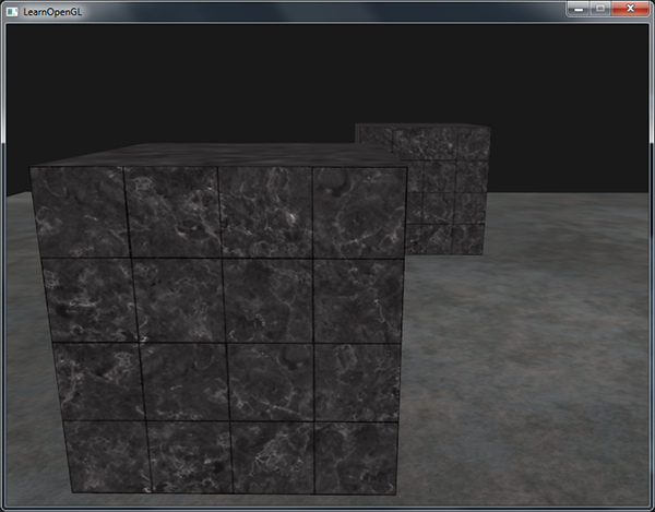
Returning the GL_LESS operator , we get the correct scene:
The issue of accuracy of depth values
The values in the depth buffer are limited by the interval [0.0, 1.0] and against them the z-component of all scene objects is checked from the point of view of the observer. In this case, the z-component of the object in the species space can take any value in the interval [zNear, zFar], which determines the near and far border of the projection pyramid ( projection frustum ). To eliminate this discrepancy, we need a way to convert the values of the z-component in the species space to the interval [0.0, 1.0]. The first, naive, way is a simple linear transformation:

Note that all the considered dependencies give a value tending to 0.0 for close objects and tending to 1.0 for objects lying near the far clipping plane.
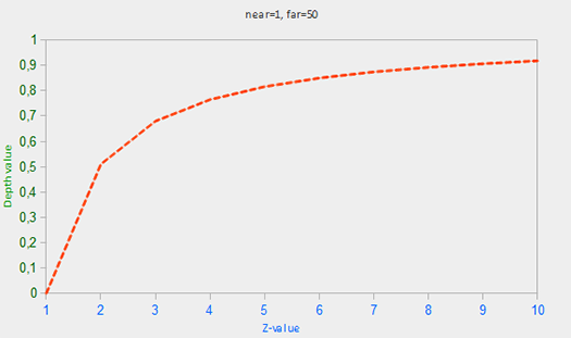
However, in practice, the linear depth buffer is practically not used. To achieve a high-quality projection result, a dependence proportional to 1 / z is used. The result of using this dependence is the high accuracy of the depth values for small z and much lower accuracy for large z. Think about the meaning of this behavior: are the accuracy of depth values for objects that are thousands of arbitrary units away from the observer really the same important for us as for detailed objects directly in front of the observer? Using linear transform does not take this issue into account.
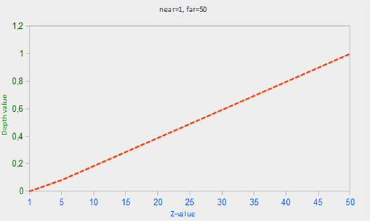
Since the nonlinear transformation is proportional to 1 / z, for z values in the interval [1.0, 2.0] we obtain depth values in the interval [1.0, 0.5], which already covers half the precision of the float type, providing tremendous accuracy for small z. The z values from the interval [50.0, 100.0] will be provided with only 2% of the available precision of the float type - but this is exactly what we need. So, a new dependence, including taking into account the parameters zNear and zFar of the projection matrix:

As you can see, the depth values vary greatly for small input z, giving us increased accuracy in the region near the near clipping plane. The expression for the transformation of z values (from the observer's point of view) is embedded in the structure of the projection matrix. Thus, when we translate the coordinates of the vertices from the view space into the clips space and then into the screen space, we use a nonlinear transformation of z values. If you want to understand in detail the mechanics of the projection matrix, then I recommend this wonderful article .
The effect of non-linearity is easy to notice when trying to visualize the depth buffer.
Visual representation of depth buffer values.
So, in the vertex shader, the fragment depth value is available to us through the z-component of the built-in variable gl_FragCoord . If we output this value as a color value, then we can visualize the contents of the current depth buffer:
void main()
{
    FragColor = vec4(vec3(gl_FragCoord.z), 1.0);
}
If you try to run the application, then, most likely, everything will be filled with white, giving the impression that all objects have a depth of 1.0 - the maximum possible value. Why do we not see darker areas where the depth approaches zero?
From the previous section, we remember that in the screen space the depth buffer values are non-linear, i.e. for small z, the accuracy is high, and for large z is small. The depth value very quickly increases with the distance in the scene, because almost all the vertices quickly reach a depth close to 1.0. If we carefully come closer to one of the objects, then in the end we can distinguish between the darkening of their near parts with a decrease in the value of z:
The nonlinear nature of the depth values is clearly visible here. In nearby objects, the depth value changes much faster than in distant objects. The slightest movement of the camera changes color from almost black to pure white.
However, we have the opportunity to convert non-linear values of the fragment depth back to linearly distributed ones. To do this, we need to literally reverse the projection process, but only for depth values. The first step is to convert the depth values back from the interval of values [0.0, 1.0] to the interval [-1.0, 1.0] corresponding to the normalized device coordinates ( NDC, normalized device coordinates ) of the clipping space. Then we derive the expression inverse to the nonlinear expression (2), and apply it to the obtained depth value. The result is a linear depth value. Sounds quite capable of us, do you think?
So, for starters, translate the depth value to NDC:
float z = depth * 2.0 - 1.0; Next, we transform the obtained value of z into a linear one using the inverse relation (2) :
float linearDepth = (2.0 * zNear * zFar) / (zFar + zNear - z * (zFar - zNear));
I recall that this expression was obtained for projection matrices using expression (2) for nonlinear transformation of depth values, also limiting them to the interval [zNear, zFar]. I again give a link to an article full of mathematical details of the internal structure of the projection matrix. You can also understand from the article where the above expression comes from.
The full text of the fragment shader that converts non-linear depths into linear values in screen space:
#version 330 core
out vec4 FragColor;
float zNear = 0.1;
float zFar  = 100.0;
float LinearizeDepth(float depth)
{
    // преобразуем обратно в NDC
    float z = depth * 2.0 - 1.0;
    return (2.0 * zNear * zFar) / (zFar + zNear - z * (zFar - zNear));
}
void main()
{
    // деление на zFar для лучшей наглядности
    float depth = LinearizeDepth(gl_FragCoord.z) / zFar;
    FragColor = vec4(vec3(depth), 1.0);
}
Since linearized depths are between the zNear and zFar boundaries, most of the values will be greater than 1.0 and will be displayed as pure white. Dividing the linear value of depth by zFar in the main function code, we approximately bring it to the interval [0.0, 1.0]. This will allow us to observe a smooth increase in the brightness of scene objects with their approach to the far plane of the projection pyramid, which is much clearer.
By launching the application this time, you can verify the linear nature of the change in depth with distance. Try wandering around the scene to watch the changes:
The scene is almost completely filled with black, since the depth values vary linearly from zNear = 0.1 to zFar = 100.0, which, in this case, is quite far away. And since we are near the near plane of the projection pyramid, the depth and, accordingly, the brightness values are very small.
Limited precision buffer depth artifacts
A fairly common visual artifact appears when two planes or two triangles overlap each other so close that the accuracy of the depth buffer is not enough to unambiguously resolve the order of these objects. As a result of this ambiguity, fragments of these objects constantly seem to change the arrangement, creating visual noise and patterns. The phenomenon is called z-fighting , because it looks as if the displayed figures are fighting for the possibility of overlapping another.
In the scene used there are enough places where z-fighting is noticeable: the containers are specially located at the same height as the floor, guaranteeing that the container and the bottom of the container are in the same plane. And this also means that the depth values are equal for both planes, which makes it impossible to resolve the order of these planes using the depth buffer.
If you put the camera in one of the containers, the effect will appear in all its glory. It can be seen how fragments of the floor plane constantly slip through the bottom of the drawer, creating an annoying torn pattern: Z-fighting is a common problem when using the depth buffer and is typically more noticeable for objects distant (since the accuracy of the buffer decreases at a distance). We cannot completely avoid this phenomenon, but in the arsenal of the developer there are several approaches that allow you to reduce or completely get rid of z-fighting in a particular scene.
Coping methods
The first and perhaps most important tip will never be to place objects too close to each other with the risk of overlapping their triangles . By adding a small, invisible to the user, the offset between the objects you will ensure yourself freedom from z-fighting. In our case with the plane and containers, it would be enough just to shift the containers in the direction of the positive axis Y. A sufficiently small displacement would be imperceptible, but sufficient to get rid of the artifact. However, this method requires manual modification of the scene and rigorous testing to ensure that there are no manifestations of z-fighting in the scene.
Another approach is to set the near clipping plane as far as possible.. As noted above, significant accuracy is provided near the zNear plane. Therefore, if we move the near plane from the observer, we will provide greater accuracy for the entire volume of the pyramid of visibility. However, it is worth remembering that excessive displacement of the near plane can lead to a noticeable truncation of objects in the vicinity. So this approach requires a certain amount of sample and fit in order to successfully select the zNear value.
The third method simply suggests using the depth buffer format with greater precision., for which you have to pay with a share of productivity. In most cases, buffers with an accuracy of 24 bits are used, but modern video cards allow the use of accuracy of 32 bits for the depth buffer. Additional accuracy will reduce the effect of z-fighting, but it will cost you speed.
These three techniques for getting rid of z-fighting are the most common and easy to implement. There are other ways that are more time-consuming, but still not guaranteeing a complete solution to the problem. Indeed, z-fighting is a typical problem, but with careful use of these techniques, you probably will not have to deal with the manifestations of this artifact at all.
PS: one of the commentators of the original article gives a hint about two methods that 100% eliminate z-fighting: using a stencil buffer when rendering in several approaches; and using the SGIX_reference_plain extension.