It is not enough to count polygons to optimize 3D models.
- Transfer
Having dealt with the basics of the mesh rendering process, you can use various techniques to optimize the rendering speed.
Introduction
How many polygons can I use? This is a very common question that artists ask when creating models for real-time rendering. This question is difficult to answer, because it is not only in numbers.
I started my career as a 3D artist in the era of the first PlayStation, and later became a graphics programmer. I would like to read this article before I first started creating 3D models for games. The fundamentals discussed in it will be useful to many artists. Although most of the information in this article will not significantly affect the productivity of your daily work, it will give you a basic understanding of how the graphics processing unit (GPU) draws the meshes you create.
The number of polygons in the mesh usually depends on the speed of its rendering. However, despite the fact that the number of polygons often correlates with the frame rate per second (FPS), you may find that even after reducing the number of polygons, the mesh is still rendered slowly. But having understood how the meshes are rendered as a whole, you will be able to apply a set of techniques to increase the rendering speed.
How are polygon data presented
To understand how the GPU draws polygons, you must first consider the data structure used to describe polygons. A polygon consists of a set of points, called vertices, and links. Vertices are often stored as arrays of values, for example, like Figure 1.
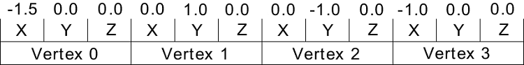
Figure 1. Array of simple polygon values.
In this case, four vertices in three dimensions (x, y, and z) give us 12 values. To create polygons, the second array of values describes the vertices themselves, as shown in Figure 2.

Figure 2. Array of links to vertices.
These vertices, joined together, form two polygons. Notice that two triangles, each with three angles, can be described by four vertices, because vertices 1 and 2 are used in both triangles. In order for this data to be processed by the GPU, it is assumed that each polygon is triangular. GPUs expect you to work with triangles, because they are designed to render them. If you need to draw polygons with a different number of vertices, then you need an application that divides them into triangles before drawing to the GPU. For example, if you create a cube of six polygons, each of which has four sides, then it is no more efficient than creating a cube of 12 polygons consisting of three sides; these triangles will draw the GPU. Remember the rule: you need to count not polygons, but triangles.
The vertex data used in the previous example is three-dimensional, but this is optional. Two dimensions may be enough for you, but it is often necessary to store other data, for example, UV coordinates for textures and normals for lighting.
Polygon drawing
When drawing a polygon, the GPU first determines where to draw the polygon. To do this, it calculates the position on the screen where there should be three vertices. This operation is called transform. These calculations in the GPU are performed by a small program called the “vertex shader”.
The vertex shader often performs other types of operations, such as animation processing. After calculating the positions of all the vertices of the polygon, the GPU calculates which pixels are in this triangle, and then starts filling those pixels with another small program called the fragment shader. The fragment shader is usually executed once per pixel. However, in some rare cases, it can be performed several times per pixel, for example, to improve anti-aliasing. Fragment shaders are often called pixel shaders, because in most cases, fragments correspond to pixels (see Figure 3).
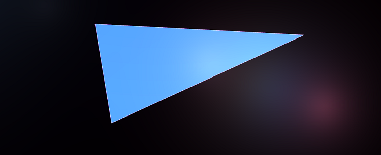
Figure 3. One polygon drawn on the screen.
Figure 4 shows the order of actions performed by the GPU when drawing a polygon.

Figure 4. The procedure for GPU rendering a polygon.
If you divide the triangle into two and draw both triangles (see Figure 5), then the procedure will be in accordance with Figure 6.

Figure 5. Dividing a polygon into two.

Figure 6. The procedure for a GPU that draws two polygons.
In this case, it takes two times more transformations and preparations, but since the number of pixels remains the same, the operation does not need to rasterize additional pixels. This shows that doubling the number of polygons does not necessarily double the rendering time.
Using Vertex Cache
If you look at the two polygons from the previous example, you can see that they have two common vertices. It can be assumed that these vertices will have to be computed twice, but a mechanism called vertex cache (vertex cache) allows you to reuse the results of calculations. The results of the vertex shader calculations for reuse are stored in the cache - a small memory area containing the last few vertices. The procedure for drawing two polygons using the vertex cache is shown in Figure 7.

Figure 7. Drawing two polygons using the vertex cache.
Thanks to the vertex cache, you can draw two polygons almost as quickly as one if they have common vertices.
Understanding the vertex parameters
In order for a vertex to be reused, it must be constant at every use. Of course, the position should remain the same, but other parameters should not change either. The parameters passed to the top depend on the engine used. Here are two common parameters:
- Texture coordinates
- Normals
When UV-imposing on a 3D object, any created seam will mean that the vertices along the seam cannot be shared. Therefore, in general, seams should be avoided (see Figure 8).
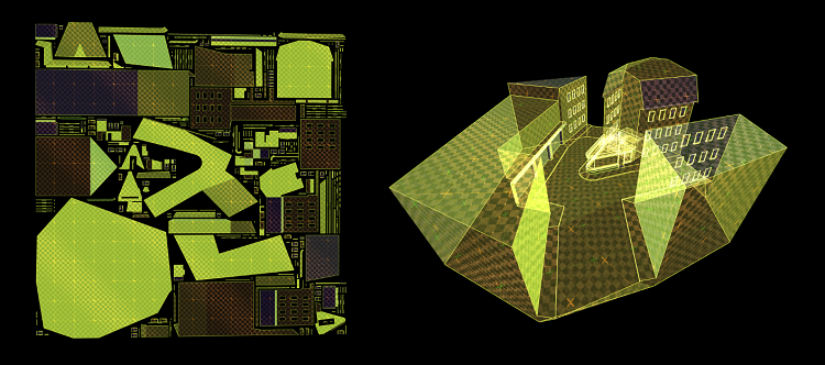
Figure 8. UV suturing texture.
For proper illumination of the surface, each vertex usually stores a normal — a vector directed from the surface. Due to the fact that all polygons with a common vertex are set by the same normal, their shape seems to be smooth. This is called smooth shading. If each triangle has its own normals, then the edges between the polygons become pronounced, and the surface appears flat. Therefore, this is called flat shading. Figure 9 shows two identical meshes, one with smoothed shading, and the other with a flat one.
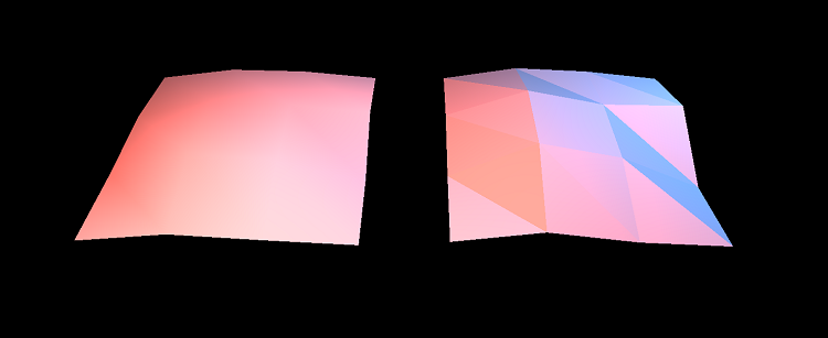
Figure 9. Comparison of smooth with flat shading.
This geometry with smoothed shading consists of 18 triangles and has 16 common vertices. For flat shading of 18 triangles, 54 (18 x 3) vertices are needed, because none of the vertices is common. Even if two meshes have the same number of polygons, the speed of their drawing will still be different.
Importance of form
GPUs work fast mainly because they can perform multiple operations in parallel. GPU marketing materials often focus on the number of their pipelines (pipeline), which determine the number of operations that a GPU can perform at the same time. When the GPU renders the polygon, it gives the task to fill the squares of pixels to multiple pipelines. This is usually an eight by eight pixel square. The GPU continues to do this until all the pixels are filled. Obviously, the triangles are not squares, so some pixels of the square will be inside the triangle, and others outside. The equipment works with all pixels of a square, even those that are outside the triangle. After calculating all the vertices in the square, the equipment discards pixels outside the triangle.
Figure 10 shows a triangle, which requires three squares (tiles) to be drawn. Most of the calculated pixels (blue) are used, and those shown in red fall outside the bounds of the triangle and will be discarded.
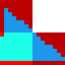
Figure 10. Three tiles for drawing a triangle.
The polygon in Figure 11 with exactly the same number of pixels, but stretched, requires more tiles to fill; Most of the work results in each tile (red area) will be discarded.

Figure 11. Filling the tiles in a stretched image.
The number of pixels drawn is only one of the factors. Also important is the shape of the polygon. To increase efficiency, try to avoid long, narrow polygons and give preference to triangles with approximately the same length of sides, the angles of which are close to 60 degrees. The two flat surfaces in Figure 12 are triangulated in two different ways, but look the same when rendered.
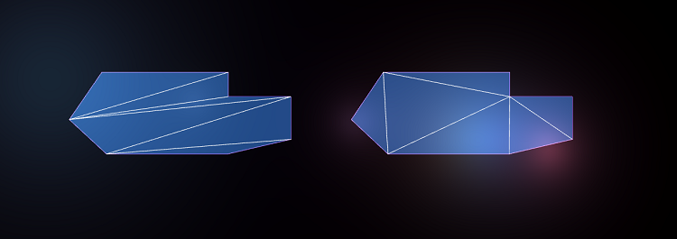
Figure 12. Surfaces triangulated in two different ways.
They have exactly the same number of polygons and pixels, but since the surface of the left has longer, narrower polygons than that of the right, its rendering will be slower.
Redrawing
To draw a six-pointed star, you can create a mesh of 10 polygons or draw the same shape from just two polygons, as shown in Figure 13.
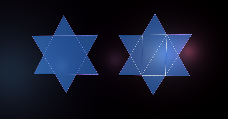
Figure 13. Two different ways of drawing a six-pointed star.
You can decide that two polygons are faster than 10. However, in this case, this is most likely wrong, because the pixels in the center of the star will be drawn twice. This phenomenon is called overdraw. In essence, it means that pixels are redrawn more than once. Redrawing occurs naturally throughout the rendering process. For example, if a character is partially hidden by a column, then it will be drawn entirely, despite the fact that the column overlaps a part of the character. Some engines use complex algorithms to avoid drawing objects that are invisible in the final image, but this is a difficult task. It is often harder for the CPU to figure out what not to draw, than the GPU to draw it.
When working as an artist, you have to accept the fact that you cannot get rid of redrawing, but it is good practice to remove surfaces that cannot be seen. If you are collaborating with the development team, then ask to add a debugging mode in the game engine, in which everything becomes transparent. This will make it easier to find hidden polygons that can be deleted.
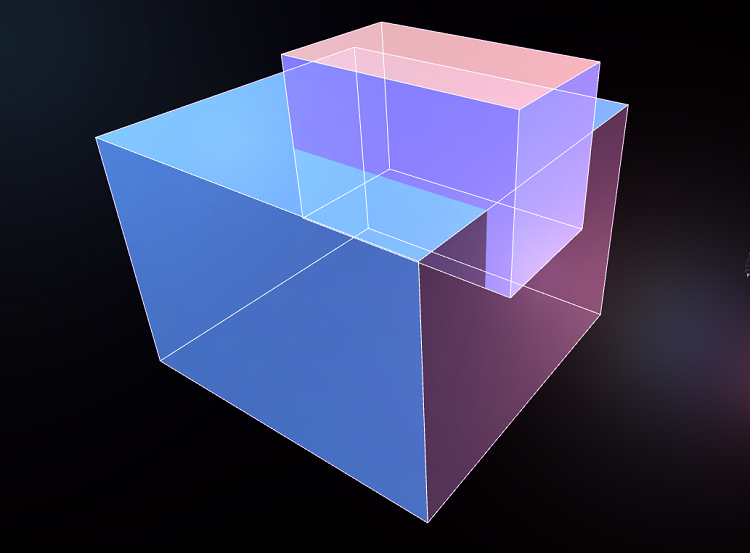
The implementation of the box on the floor
Figure 14 shows a simple scene: a box on the floor. The floor consists of only two triangles, and the box consists of 10 triangles. Redrawing in this scene is shown in red.
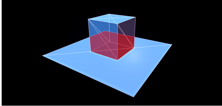
Figure 14. Standing on the floor box.
In this case, the GPU will draw a part of the floor with a box, despite the fact that it will not be visible. If instead we had created a hole in the floor under the box, we would have received more polygons, but much less redrawing, as can be seen from Figure 15.
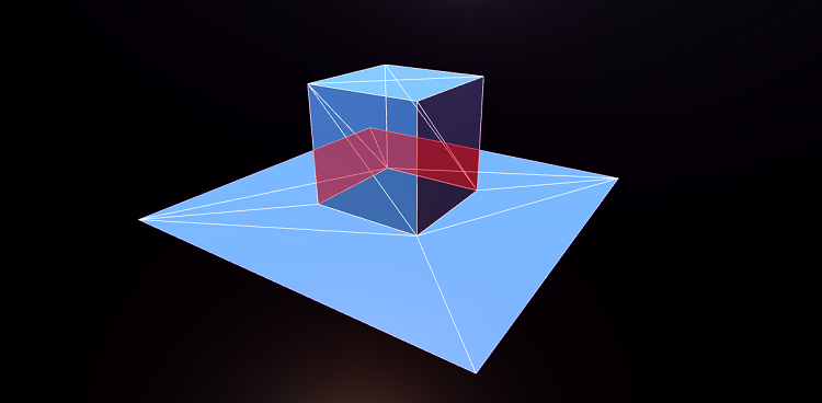
Figure 15. A hole under the box to avoid redrawing.
In such cases, it all depends on your choice. Sometimes it is worth reducing the number of polygons, having received a redraw in return. In other situations, it is worth adding polygons to avoid redrawing. Another example: the two figures shown below are equally looking surface meshes with spikes protruding from it. In the first mesh (Figure 16), the tips are located on the surface.
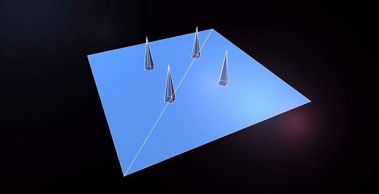
Figure 16. Points are located on the surface.
In the second mesh in Figure 17, holes are cut in the surface under the tips to reduce the amount of redrawing.

Figure 17. The holes are cut under the tips.
In this case, a lot of polygons were added to cut holes, some of which have a narrow shape. In addition, the redrawing surface, which we got rid of, is not very large, so in this case this technique is ineffective.
Imagine you are modeling a house standing on the ground. To create it, you can either leave the ground unchanged, or cut a hole under the house in the ground. Redraw more in the case when the hole is not cut under the house. However, the choice depends on the geometry and the point of view from which the player will see the house. If you draw the earth under the base of the house, it will create a large amount of redrawing, if you go inside the house and look down. However, the difference will not be particularly large if you look at the house from an airplane. In this case, it’s best to have a debugging mode in the game engine that makes the surfaces transparent so that you can see what is being drawn under the surfaces visible to the player.
When Z-buffers have a Z-conflict
When a GPU renders two overlapping polygons, how does it determine which one is on top of the other? The first computer graphics researchers spent a lot of time researching this problem. Ed Catmell (who later became president of Pixar and Walt Disney Animation Studios) wrote an article that outlined ten different approaches to this task. In one part of the article, he notes that the solution to this problem will be trivial if the computers have enough memory to store one value of depth per pixel. In the 1970s and 1980s, it was a very large amount of memory. However, today most GPUs work this way: this system is called a Z-buffer.
The z-buffer (also known as the depth buffer) works as follows: its value is associated with each pixel. When the equipment draws an object, it calculates how far away a pixel is drawn from the camera. It then checks the depth value of an already existing pixel. If it is farther from the camera than the new pixel, then the new pixel is drawn. If the existing pixel is closer to the camera than the new one, then the new pixel is not drawn. This approach solves many problems and works even if the polygons intersect.
Figure 18. Intersecting polygons processed by the depth buffer.
However, the Z-buffer does not have infinite accuracy. If the two surfaces are almost the same distance from the camera, then this confuses the GPU and it can randomly select one of the surfaces, as shown in Figure 19.
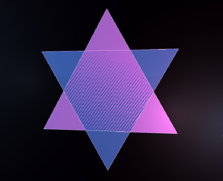
Figure 19. Surfaces at the same depth display problems.
This is called Z-fighting and looks very buggy. Often, Z-conflicts become worse the farther the surface is from the camera. Engine developers can build patches in them to smooth out this problem, but if the artist creates reasonably close and overlapping polygons, the problem can still arise. Another example is a wall with a poster hanging on it. The poster is almost at the same depth from the camera as the wall behind it, so the risk of Z-conflicts is very high. The solution is to cut a hole in the wall under the poster. This also reduces the amount of redrawing.
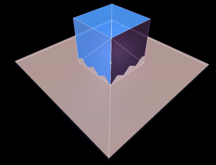
Figure 20. An example of Z-conflict overlapping polygons.
In extreme cases, Z-conflict may occur even when objects touch each other. Figure 20 shows the box on the floor, and since we did not cut a hole in the floor under the box, the z-buffer can be confused near the edge where the floor meets the box.
Using draw calls
GPUs have become extremely fast - so fast that CPUs may not keep up with them. Since GPUs are essentially designed to perform a single task, they are much easier to get to work fast. Graphics is inherently related to the calculation of a set of pixels, so you can create equipment that calculates a set of pixels in parallel. However, the GPU renders only what it orders to draw the CPU. If the CPU cannot quickly “feed” the GPU with data, then the video card will be idle. Every time the CPU orders the GPU to draw something, it is called a draw call. The simplest draw call consists of drawing one mesh, including one shader and one set of textures.
Imagine a slow processor capable of transmitting 100 draw calls per frame, and a fast GPU that can draw millions of polygons per frame. In this case, the ideal draw call can draw 10,000 polygons. If your meshes consist of just 100 polygons, then the GPU can only draw 10,000 polygons per frame. That is, 99% of the time the GPU will be idle. In this case, we can easily increase the number of polygons in the mesh, without losing anything.
What the draw call consists of and the cost of it depends heavily on specific engines and architectures. Some engines can combine many meshes into one draw call (execute their batching, batch), but all meshes will have to have the same shader, or they may have other restrictions. New APIs like Vulkan and DirectX 12 are designed specifically to solve this problem by optimizing how the program communicates with the graphics driver, thus increasing the number of draw calls that can be sent in one frame.
If your team is writing its own engine, then ask the engine developers what limitations the draw calls have. If you are using a ready-made engine like Unreal or Unity, then perform performance benchmarks to determine the limits of the engine's capabilities. You may find that you can increase the number of polygons without causing a decrease in speed.
Conclusion
I hope this article will serve as a good introduction to help you understand the various aspects of rendering performance. In GPUs from different manufacturers, everything is implemented a bit differently. There are many reservations and special conditions associated with specific engines and hardware platforms. Always maintain an open dialogue with rendering programmers to use their recommendations in your project.
about the author
Eskil Steenberg (Eskil Steenberg) - an independent developer of games and tools, he works as a consultant, and on independent projects. All screenshots are made in active projects using tools developed by Eskil. You can learn more about his work on the Quel Solaar website and in the @quelsolaar account on Twitter.