EVPN Multihoming

In an EVPN article, I touched on multihoming. This topic was of interest to many people, and therefore, in the continuation of the previous article today we will consider what EVPN multihoming is and how it works.
EVPN multihoming works in two modes: Single-Active and Active-Active. Today, we mainly focus on a more complex and interesting option: Active-Active, since Single-Active is essentially a very simplified version of Active-Active.
This article is intended for those who already have general knowledge about EVPN: the basic principles of work, differences from VPLS, etc. Otherwise, it will be difficult to understand the contents of the article.
Note: I assembled the laboratory stand in EVE-NG using vMX: how P-router and switches run vMX version 14.1, like PE-routers vMX 16.1, as the final host for 5 Linux machines. Unlike the last lab that I collected on a laptop, this lab is too demanding on resources. The fact is that vMX 16.1 runs on two virtual machines and requires a total of 4 CPUs and 8GB RAM. As a result, the labs presented in the article need about 35 GB RAM on the server, but I want to note that in the working state the whole lab occupied a little more than 23 GB RAM (this should be borne in mind if you suddenly want to raise this lab at home).
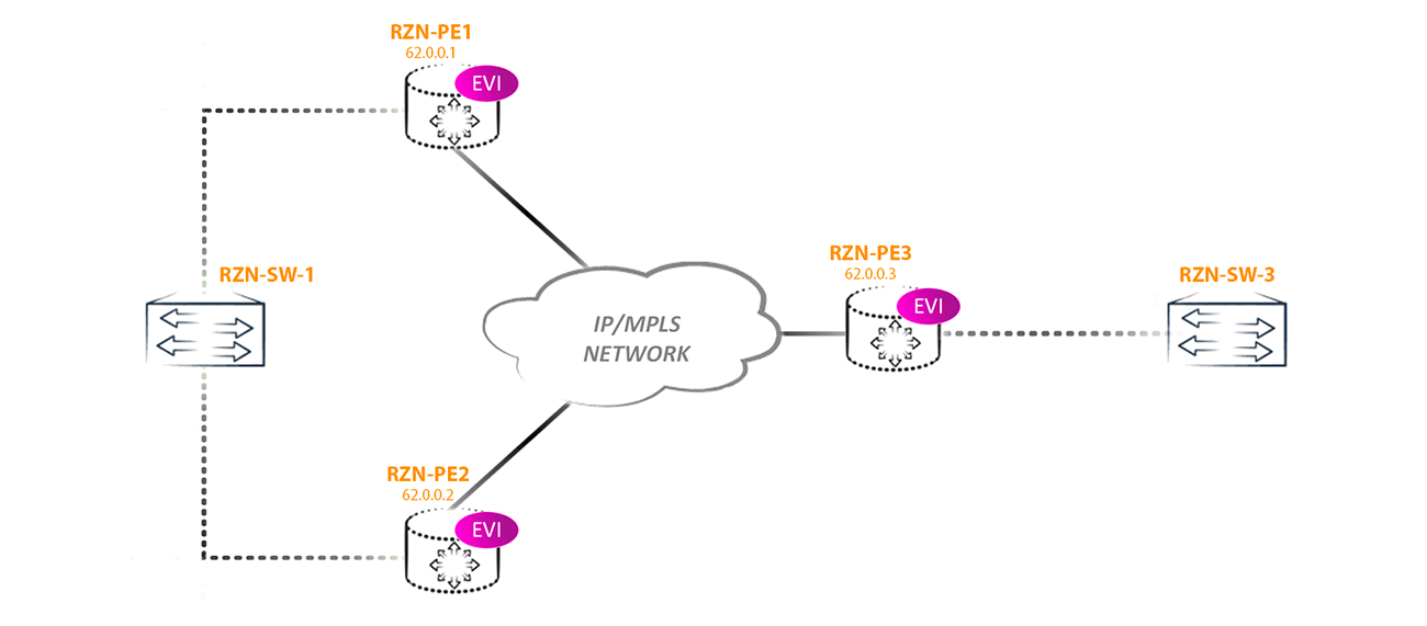
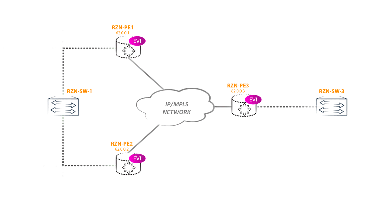
We will consider this topology:
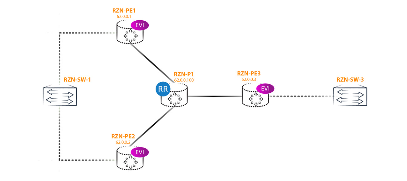
In the configuration, I will use the vlan-aware method, that is, through a virtual switch, since this method is the most flexible and interesting, at least for me. Three EVPN instances (EVI for EVPN Instance) were created on each PE router, the configuration of which is approximately the same on all three PEs — the differences are only in RD, RT, and Vlan numbers. Two other instances are added only to demonstrate some of the features of the EVPN Multihoming clearly.
The configuration of EVPN instances is as follows:
bormoglotx@RZN-PE-1> show configuration routing-instances vSwitch-eVPN-1
instance-type virtual-switch;
interface ae3.777;
route-distinguisher 62.0.0.1:1;
vrf-target target:42000:1;
protocols {
    evpn {
        extended-vlan-list 777;
    }
}
bridge-domains {
    BRIDGE-777 {
        vlan-id 777;
    }
}
Nothing complicated: an instance with the type of virtual switch, RT, RD, and just one bridge domain with vlan-id 777. The same vlan is listed in the extended list of evpn protocol vlans. For testing, we do not need anything else.
Now let's move on to the configuration of the interfaces. On RZN-PE-3, everything is simple and corny:
bormoglotx@RZN-PE-3> show configuration interfaces ae0
description "RZN-SW-3 | ae0";
flexible-vlan-tagging;
encapsulation flexible-ethernet-services;
aggregated-ether-options {
    lacp {
        active;
        periodic fast;
    }
}
unit 777 {
    description eVPN-1;
    encapsulation vlan-bridge;
    family bridge {
        interface-mode trunk;
        vlan-id-list 777;
    }
}
A simple aggregate that acts as a trunk interface in which only 777 vlan are allowed.
But on PE1 and PE2, the config is somewhat different from PE3, since the PE data is multihomed to RZN-SW-1:
bormoglotx@RZN-PE-1> show configuration interfaces ae3
description "RZN-SW-1 | ge-0/0/0 | ae3<<>>ae0 ";
flexible-vlan-tagging;
mtu 1600;
encapsulation flexible-ethernet-services;
esi {
    00:00:00:00:00:00:00:00:00:01;
    all-active;
}
aggregated-ether-options {
    lacp {
        active;
        periodic fast;
        system-id 02:00:00:00:00:01;
    }
}
unit 777 {
    description eVPN-1;
    encapsulation vlan-bridge;
    family bridge {
        interface-mode trunk;
        vlan-id-list 777;
    }
}
Here we are interested in the ESI identifier that has appeared. Let me remind you for those who forgot (or did not know) - this identifier must be assigned manually (when using MC-LAG it can be generated automatically), and for all interfaces connected to the same segment this identifier must be the same.
Note: for what purpose the system-id is indicated here will be described at the end of the article
In our case, I chose a simple identifier 00: 00: 00: 00: 00: 00: 00: 00: 00: 01, since its value does not play a big role for us, the main thing is that it is different from the reserved values (all zeros and all units) and did not intersect with the value of the already configured ESI values in other segments. That is, roughly speaking, ESI should be unique for the entire network where EVPN is launched. For non-multihoming segments, this identifier does not play any role whatsoever and is automatically set to 0. Naturally, even for non-multihoming PE routers, you can handle and set a non-zero ESI value on the links, and this will only entail the generation of unnecessary routes - that is, in fact, there will be no problems as such.
There are 5 types of routes in EVPN (I didn’t consider Type 5 the last time, but I’ll try to cover this topic in the EVPN / VxLAN article):
Type 2 is a MAC / IP route. This route tells the PE router where and with what label to send unicast packets to the specific mac address specified in the route. Essentially similar to the announcement of the vpnv4 prefix in L3VPN. The route may also contain the host ip address.
Type 3 is the Inclusive Multicast route. This route tells the PE router where and with what label to send BUM traffic.
Type 1 and 4 are the main routes that provide us with EVPN Multihoming functionality. We will consider them further.
So, at the 0-th moment of time, as soon as we started EVPN, the routers start sending routes of type 3 to each other so that it would be possible to exchange BUM traffic. This is true for a scenario without multihoming. Since two routers in our segment are looking at the same segment, we get routes of type 1 and 4. Why do we need a route of type 3 you should already know, so we will focus on routes of type 1 and 4. Further,
as I wrote above - we just launched EVPN and so far there has been no traffic exchange between the hosts, as the absence of MAC addresses in the forwarding table of the vSwitch-eVPN-1 instance tells us:
bormoglotx@RZN-PE-1> show evpn instance vSwitch-eVPN-1 brief
                            Intfs       IRB intfs         MH      MAC addresses
Instance                    Total   Up  Total   Up  Nbrs  ESIs    Local  Remote
vSwitch-eVPN-1                  1    1      0    0     2     1        0       0
In the presented output, we see that we have a multihomed segment. To find out information about this segment, we will consider the extensive output of the previous command:
bormoglotx@RZN-PE-1> show evpn instance vSwitch-eVPN-1 extensive
Instance: vSwitch-eVPN-1
  Route Distinguisher: 62.0.0.1:1
  Per-instance MAC route label: 299792
  Per-instance multicast route label: 299776
  MAC database status                     Local  Remote
    MAC advertisements:                       0       0
    MAC+IP advertisements:                    0       0
    Default gateway MAC advertisements:       0       0
  Number of local interfaces: 1 (1 up)
    Interface name  ESI                            Mode             Status
    ae3.777         00:00:00:00:00:00:00:00:00:01  all-active       Up
  Number of IRB interfaces: 0 (0 up)
  Number of bridge domains: 1
    VLAN  Domain ID   Intfs / up    IRB intf   Mode             MAC sync  IM route label
    777                  1    1                Extended         Enabled   299776
  Number of neighbors: 2
    62.0.0.2
      Received routes
        MAC address advertisement:              0
        MAC+IP address advertisement:           0
        Inclusive multicast:                    1
        Ethernet auto-discovery:                2
    62.0.0.3
      Received routes
        MAC address advertisement:              0
        MAC+IP address advertisement:           0
        Inclusive multicast:                    1
        Ethernet auto-discovery:                0
  Number of ethernet segments: 1
    ESI: 00:00:00:00:00:00:00:00:00:01
      Status: Resolved by IFL ae3.777
      Local interface: ae3.777, Status: Up/Forwarding
      Number of remote PEs connected: 1
        Remote PE        MAC label  Aliasing label  Mode
        62.0.0.2         300208     300208          all-active
      Designated forwarder: 62.0.0.2
      Backup forwarder: 62.0.0.1
      Last designated forwarder update: May 07 06:59:19
      Advertised MAC label: 300112
      Advertised aliasing label: 300112
      Advertised split horizon label: 302752
This conclusion gives us complete information on our EVPN instance. Some of the fields should already be clear to you. According to this conclusion, we have ESI 00: 00: 00: 00: 00: 00: 00: 00: 00: 01, which works in Active-Active mode:
Number of local interfaces: 1 (1 up)
    Interface name  ESI                            Mode             Status
    ae3.777         00:00:00:00:00:00:00:00:00:01  all-active       Up
The following is the output for each PE router participating in this EVPN domain:
    Number of neighbors: 2
    62.0.0.2
      Received routes
        MAC address advertisement:              0
        MAC+IP address advertisement:           0
        Inclusive multicast:                    1
        Ethernet auto-discovery:                2
Judging by the information above from RZN-PE-2, we get one route of type 3 and two routes of type 1. True, this is not entirely true. In addition to these routes, RZN-PE-2 gives us another type 4 route, but we will see later why it is not shown here.
But from RZN-PE-3 at the moment we get only one type 3 route and that's it:
    62.0.0.3
      Received routes
        MAC address advertisement:              0
        MAC+IP address advertisement:           0
        Inclusive multicast:                    1
        Ethernet auto-discovery:                0
This is logical, since this PE router is not multihomed, and so far all we need to know from it is a type 3 route. Later, as we learn poppies, this router will start sending out type 2 announcements, but so far it has not learned any poppies. If we had default gateways configured, then there would still be type 2 routes (depending on the number of irb interfaces added to the instance).
In addition to the information described above for our EVI, the output indicates that for the segment with ESI 00: 00: 00: 00: 00: 00: 00: 00: 00: 01 Designated forwarder is selected and the Aliasing label is indicated:
  Number of ethernet segments: 1
    ESI: 00:00:00:00:00:00:00:00:00:01
      Status: Resolved by IFL ae3.777
      Local interface: ae3.777, Status: Up/Forwarding
      Number of remote PEs connected: 1
        Remote PE        MAC label  Aliasing label  Mode
        62.0.0.2         300208     300208          all-active
      Designated forwarder: 62.0.0.2
      Backup forwarder: 62.0.0.1
At the moment, many of the conclusions are not clear. To understand the principles of the EVPN Multihoming, we need to deal with at least the following issues:
1. Why does the Multihomed PE router begin to announce additional routes of type 1 and 4, what is their purpose;
2. What is DF and how are its elections;
3. Why there are already two routes of type 1.
4. What is the Aliasing label in the output above.
But I will try to answer these and some other questions further.
Multihoming problems ha.
To begin, let's outline what problems we will have if we turn on Multihoming in Active-Active mode. Naturally, the most acute problem will be loops (well, or loops, as you like), since EVPN is still L2VPN. In fact, if you defeat this problem, then the technology will already be better than the same VPLS, which in All-Active mode does not know how to work at all. Another important problem will be traffic balancing, since not all multihomed PE routers will learn poppies from the client. Other problems are less critical, or rather, to put it this way - although there are other problems, their presence does not make the technology unviable.
Let's look at how these issues are resolved in EVPN.
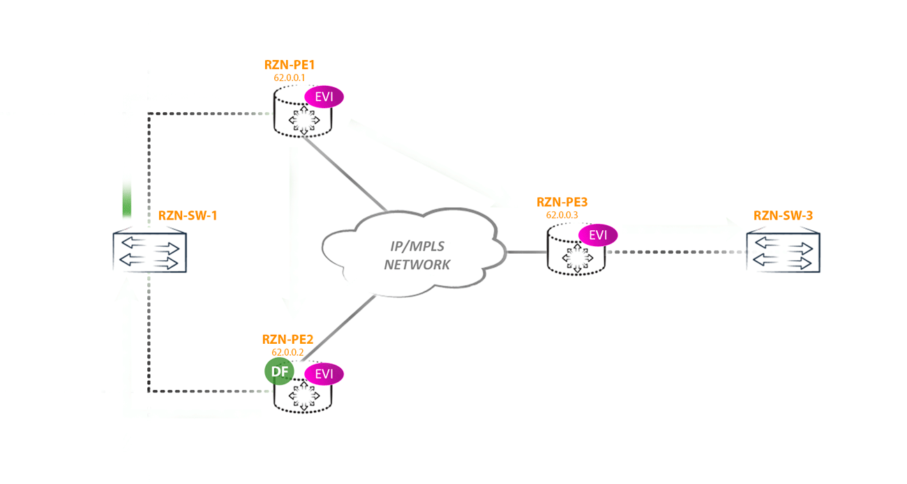
Fighting loops has a whole range of measures. The first is naturally split horizon - a frame received from other PE routers (i.e. from the kernel) is not sent again to the kernel. But naturally, this is not enough, since the main place of the network where a loop can occur is connecting the multihomed CE switch to several PE routers. To eliminate the loops in this segment, Designated Forwarder and Split Horizon Label are used, but first things first.
What is DF and why is it needed?
The first scenario of the loop: imagine that the remote PE router receives traffic from the CE BUM (for example, a banal arp request) and sends it to all other PEs (suppose this is PE3). Since two PE routers (PE1 and PE2) look at the same segment and they both receive BUM traffic from PE3, it turns out that two copies of traffic will arrive in this segment, which will then begin to loop through all networks, including the core:
To combat this phenomenon in EVPN, for each multihomed segment, Designated Forwarder is selected - the node that is responsible for forwarding BUM traffic to a specific segment in a specific vlan. All other routers, no matter how many there are in the segment, do not have the right to send BUM traffic to the CE of the router / switch (in this ESI in this vlan).
The DF selection algorithm:
1. First, all PE routers should understand how many more routers are connected to the specified segment and what their addresses are (loopbacks);
2. After the timer expires (default is 3 seconds), a list of all PE routers participating in the DF selection is formed, starting from the lowest address and ending with the largest. The list of addresses is numbered from 0;
3. According to the formula V mod N = i, DF is calculated for a given segment and vlan;
4. The router selected by DF will enable the transmission of BUM traffic to CE, and all other non-DF routers continue to block BUM traffic to CE of the router / switch in this segment in this vlan.
In theory, everything is simple, but let's take it in order.
First, we answer the question of how routers understand who else has a link in the same segment (and are there any routers at all)? For this, there is a route of type 4. Let's look at this route:
bormoglotx@RZN-PE-1> show route table vSwitch-eVPN-1.evpn.0 match-prefix *4:6*
vSwitch-eVPN-1.evpn.0: 9 destinations, 9 routes (9 active, 0 holddown, 0 hidden)
There are no such routes in the routing table of our EVPN instance. The fact is that only routes whose extended community corresponds to the import configured in the instance fall into this table. For example, for vSwitch-eVPN-1 is:
bormoglotx@RZN-PE-1> show configuration routing-instances vSwitch-eVPN-1 vrf-target
target:42000:1;
It turns out that the type 4 route has something different from the community configured for import. This is because routes in evpn can be generated in two ways - per-EVI and per-ESI.
per-EVI - this route is generated by a specific instance of
per-ESI - this route is generated not by a specific instance, but by a router for all connections having a link in this ESI. The same segment can be included in several evpn instances (for example, the ae3.777 interface is added to the EVPN1 instance, and ae3.778 is added to the EVPN2, although these are different units, but the ESI is fully configured for the entire interface, which means data interfaces will be the same ESI, although they are in different EVI).
Routes generated by per-EVI must have native RT and RD instances from which these routes are advertised (or some other RT, if they are additionally hung by the export policy - that is, added manually by administrators). Routes of type 2 and 3 are always generated per-EVI, which means that they always have a native RD and RT instance in the route from which these routes are announced. But for the routes generated by per-ESI, everything is somewhat more complicated and depends on the type of route.
But we continue to deal with a type 4 route.
This route is always generated per-ESI. The RD for this route will be automatically generated by the router from the router-id (if specified) or the loopback address (since this route does not apply to any of the EVPN instances). RT is also not specified manually, but is generated from ESI and only those routers that have the same ESI import this route. That is why in the conclusion considered earlier at the beginning of the article we don’t see that the multihomed neighbor announces a route of type 4 to us.
Note: in general, this is not entirely true, since only part of the ESI bits are taken for RT and all PEs that have the same ESI bits used to generate RT will import this route.
Note: JunOS generates RD for per-ESI routes using the null value in the second part of RD: 62.0.0.1: 0 .
So where to look for our type 4 route? There are several routing tables in JunOS. EVPN routes first fall into the bgp.evpn.0 table and from it are already imported into some other routing tables (secondary tables). Therefore, this route can be found in the bgp.evpn.0 table, from which it is exported to the __default_evpn __. Evpn.0 table:
bormoglotx@RZN-PE-1> show route table __default_evpn__.evpn.0 match-prefix *4:6*
__default_evpn__.evpn.0: 3 destinations, 3 routes (3 active, 0 holddown, 0 hidden)
+ = Active Route, - = Last Active, * = Both
4:62.0.0.1:0::01:62.0.0.1/304 ES
                   *[EVPN/170] 02:57:15
                      Indirect
4:62.0.0.2:0::01:62.0.0.2/304 ES
                   *[BGP/170] 02:57:16, localpref 100, from 62.0.0.100
                      AS path: I, validation-state: unverified
                    > to 10.0.0.1 via ae0.1
As I said, RD is automatically generated by the router: 62.0.0.1:07 in the route from RZN-PE-1 (next-hop indirect, since the route is local to this router) and 62.0.0.2:07 in the route from RZN-PE- 2. There is no route from RZN-PE-3, since this PE router is not multihomed. Moreover, since there is no such ESI on PE-3, this router does not import these routes, although the reflector faithfully gives them to it:
bormoglotx@RZN-PE-3> show route table __default_evpn__.evpn.0
bormoglotx@RZN-PE-3>
bormoglotx@RZN-P-1> show route advertising-protocol bgp 62.0.0.3 | match 4:62
4:62.0.0.1:0::01:62.0.0.1/304
4:62.0.0.2:0::01:62.0.0.2/304 Now we will analyze this route in more detail:
bormoglotx@RZN-PE-1> show route table __default_evpn__.evpn.0 match-prefix *4:6* next-hop 62.0.0.2 detail
__default_evpn__.evpn.0: 3 destinations, 3 routes (3 active, 0 holddown, 0 hidden)
4:62.0.0.2:0::01:62.0.0.2/304 ES (1 entry, 1 announced)
        *BGP    Preference: 170/-101
                Route Distinguisher: 62.0.0.2:0
                Next hop type: Indirect, Next hop index: 0
                Address: 0xb1e55f0
                Next-hop reference count: 20
                Source: 62.0.0.100
                Protocol next hop: 62.0.0.2
                Indirect next hop: 0x2 no-forward INH Session ID: 0x0
                State:
                Local AS: 42000.62 Peer AS: 42000.62
                Age: 2:58:04    Metric2: 1
                Validation State: unverified
                Task: BGP_42000.62.62.0.0.100
                Announcement bits (1): 0-__default_evpn__-evpn
                AS path: I (Originator)
                Cluster list:  62.0.0.100
                Originator ID: 62.0.0.2
                Communities: es-import-target:0-0-0-0-0-0
                Import Accepted
                Localpref: 100
                Router ID: 62.0.0.100
                Primary Routing Table bgp.evpn.0
Nothing particularly criminal - most of the fields are peculiar to the BGP route. But here in the community line we are usually used to seeing for example domain-id, origin or target community. There are completely different community.
It is specially reserved for the EVPN community. As I wrote above, this route is generated exclusively by per-ESI and only those PE routers that need this route should receive it. And it is needed only for those PE-cams that have a link in the same ESI as the route sender. Therefore, the community of this route is generated based on the ESI and has the form es-import-target: 0-0-0-0-0-0-0.

In our case, all zeros, and I specifically took such an ESI to show that this community can only contain zeros in its second part (the first part is reserved and equal to 0x06 (type) and 0x02 (sub type), who are interested in reading RFC ) and this will not affect the performance of EVPN. As a result, in our laboratory network, only RZN-PE-1 and RZN-PE-2 import this route.
And where is ESI itself, you ask? The identifier is specified directly in the route itself: 4: 62.0.0.2: 0 :: 01 : 62.0.0.2/304 ES, just empty octets (zeros) are omitted (like ipv6). And it is not difficult to guess if two routers will have links in in different segments, but their identifiers will be 00 : 00: 00: 00: 00: 00: 00: 00: 00: 01 at the first and10 : 00: 00: 00: 00: 00: 00: 00: 00: 01 at the second, then the routes will be imported by both routers. For community, only the initial filtering occurs - the route itself will be used only if the ESI specified in the route matches the ESI on the router itself that received this route, otherwise the route will be dropped.
As soon as the router understands that it is multihomed (it understands this by the non-zero value of ESI in the interface configuration), it starts sending a route of type 4 so that all neighboring routers know about its presence on the network.
After the routes have scattered over the network, RZN-PE-1 and RZN-PE-2 find out that they are connected to the same ESI. Both routers wait for 3 seconds (by default) for type 4 routes from other PE routers, after which, based on the received routes from type 4 routes, they make a list of all nodes connected to this segment, and on all nodes this list will be the same, in our case is this:
62.0.0.1 i = 0
62.0.0.2 i = 1
After that, the routers begin to calculate who will be DF according to the formula V mod N = i, where V is the number of vlan, and N is the number of PE routers in the segment. That PE router whose number will be the result of the calculation and becomes the DF of this segment in this vlan. As you know, for each vlan there will be its own DF - it turns out some balancing of BUM traffic.
Three EVPN instances were configured in the laboratory, one vlan corresponds to each instance, I used the 777, 778, and 779 vlans. Since we have 2 multihomed PEs, the number of nodes is 2. We get that in this segment the DF for 777 vlans and 779 will select RZN-PE-2, and for 778 - RZN-PE-1, which is easy to verify:
bormoglotx@RZN-PE-1> show configuration routing-instances | display set | match interface
set routing-instances vSwitch-eVPN-1 interface ae3.777
set routing-instances vSwitch-eVPN-2 interface ae3.778
set routing-instances vSwitch-eVPN-3 interface ae3.779
bormoglotx@RZN-PE-1> show configuration interfaces ae3 | display set | match vlan-id
set interfaces ae3 unit 777 family bridge vlan-id-list 777
set interfaces ae3 unit 778 family bridge vlan-id-list 778
set interfaces ae3 unit 779 family bridge vlan-id-list 779bormoglotx@RZN-PE-1> show evpn instance vSwitch-eVPN-1 designated-forwarder
Instance: vSwitch-eVPN-1
Number of ethernet segments: 1
ESI: 00:00:00:00:00:00:00:00:00:01
Designated forwarder: 62.0.0.2bormoglotx@RZN-PE-1> show evpn instance vSwitch-eVPN-2 designated-forwarder
Instance: vSwitch-eVPN-2
Number of ethernet segments: 1
ESI: 00:00:00:00:00:00:00:00:00:01
Designated forwarder: 62.0.0.1bormoglotx@RZN-PE-1> show evpn instance vSwitch-eVPN-3 designated-forwarder
Instance: vSwitch-eVPN-3
Number of ethernet segments: 1
ESI: 00:00:00:00:00:00:00:00:00:01
Designated forwarder: 62.0.0.2This scheme has its pros and cons. The most obvious minus is the DF selection mechanism itself. As soon as a new router appears in the segment with a link to ESI X or a link falls / restores on the router towards ESI X, then DF is recalculated for this segment. Moreover, the worst situation will be the loss of the link towards ESI X on the DF router. Since the rest of the routers block the transmission of BUM traffic to the CE side of the device, for the time of detecting a DF drop and calculating a new DF, BUM traffic will be dropped by all PE routers in the segment, since at the moment they will all be non-DF. But now there is an RFC draft that describes a new DF selection procedure. But so far, everything is working as described.
It is worth mentioning that the choice of DF for vlan-aware and vlan-bundle methods is slightly different. Since a virtual switch can terminate several bridge domains, the choice of DF in this case does not occur for each vlan separately, but for all vlans at once, and the calculation uses the lowest configured vlan number. For example, we add 30.778 and 779 to the virtual switch. It is easy to calculate that if we take the lowest number of the vlan as the basis, then the DF for this segment will be PE1 - 62.0.0.1:
bormoglotx@RZN-PE-1> show evpn instance vSwitch-eVPN-1 extensive | match "domain|extended|forwarder"
  Number of bridge domains: 4
    VLAN  Domain ID   Intfs / up    IRB intf   Mode             MAC sync  IM route label
    30                   1    1                Extended         Enabled   300384
    777                  1    1     irb.1      Extended         Enabled   300384
    778                  1    1                Extended         Enabled   300384
    779                  1    1                Extended         Enabled   300384
      Designated forwarder: 62.0.0.1
      Backup forwarder: 62.0.0.2
      Last designated forwarder update: May 24 08:12:13
Now delete the 30th vlan. Now the smallest vlan number is 777, that is, now DF should become PE2 - 62.0.0.2:
 bormoglotx@RZN-PE-1> show evpn instance vSwitch-eVPN-1 extensive | match "domain|extended|forwarder"
  Number of bridge domains: 4
    VLAN  Domain ID   Intfs / up    IRB intf   Mode             MAC sync  IM route label
    777                  1    1     irb.1      Extended         Enabled   300384
    778                  1    1                Extended         Enabled   300384
    779                  1    1                Extended         Enabled   300384
      Designated forwarder: 62.0.0.2
      Backup forwarder: 62.0.0.1
      Last designated forwarder update: May 24 08:14:52
Note: in the conclusions above, and in the literature, the term Backup forwarder or Backup Designated forwarder (BDF) is used. BDF is just another name for a non-DF router. In EVPN there is no backup forwarder (as for example in OSPF DR and BDR) - there is only one DF, all the rest are non-DF or BDF. If another router appears in the segment or one of the segment routers falls, DF re-elections occur.
Now we have figured out why a type 4 route is needed and what it looks like.
But choosing DF, we won only one type of loop. But a loop can still occur if the CE router starts sending traffic to the non-DF side of the router. For example, if RZN-PE-1 is non-DF will receive BUM traffic from RZN-SW-1 then we will get a loop, because: RZN-PE-1, receiving BUM traffic from CE, will send this traffic to other PEs -shk including RZN-PE-2. RZN-PE-2, being DF for this segment, without a twinge of conscience sends traffic back towards RZN-SW-1, where it came from. The result was a loop:

And while the loop does not break the traffic, it will fly back and forth.
To avoid this, we need a type 1 route, also generated by per-ESI.
But unlike type 4 routes, type 1 routes generated by at least per-ESI, though per-EVI indicate the native community of an instance or several instances that are interested in this route (and why, we will find out a bit later):
bormoglotx@RZN-PE-1> show route table vSwitch-eVPN-1.evpn.0 match-prefix *1:6*
vSwitch-eVPN-1.evpn.0: 9 destinations, 9 routes (9 active, 0 holddown, 0 hidden)
+ = Active Route, - = Last Active, * = Both
1:62.0.0.1:1::01::0/304 AD/EVI
                   *[EVPN/170] 1d 00:09:01
                      Indirect
1:62.0.0.2:0::01::FFFF:FFFF/304 AD/ESI
                   *[BGP/170] 03:20:10, localpref 100, from 62.0.0.100
                      AS path: I, validation-state: unverified
                    > to 10.0.0.1 via ae0.1
1:62.0.0.2:1::01::0/304 AD/EVI
                   *[BGP/170] 1d 00:09:01, localpref 100, from 62.0.0.100
                      AS path: I, validation-state: unverified
                    > to 10.0.0.1 via ae0.1
Why is a type 1 per-ESI route needed?
A type 1 route has several functions.
The type-1 per-ESI generated route carries an extended community that specifies an mpls label called a split horizon label:
bormoglotx@RZN-PE-1> show route table vSwitch-eVPN-1.evpn.0 match-prefix *FFFF* detail
vSwitch-eVPN-1.evpn.0: 9 destinations, 9 routes (9 active, 0 holddown, 0 hidden)
1:62.0.0.2:0::01::FFFF:FFFF/304 AD/ESI (1 entry, 1 announced)
        *BGP    Preference: 170/-101
                Route Distinguisher: 62.0.0.2:0
                Next hop type: Indirect, Next hop index: 0
                Address: 0xb1e55f0
                Next-hop reference count: 20
                Source: 62.0.0.100
                Protocol next hop: 62.0.0.2
                Indirect next hop: 0x2 no-forward INH Session ID: 0x0
                State:
                Local AS: 42000.62 Peer AS: 42000.62
                Age: 3:20:48    Metric2: 1
                Validation State: unverified
                Task: BGP_42000.62.62.0.0.100
                Announcement bits (1): 0-vSwitch-eVPN-1-evpn
                AS path: I (Originator)
                Cluster list:  62.0.0.100
                Originator ID: 62.0.0.2
                Communities: target:42000:1 target:42000:2 target:42000:3 esi-label:all-active (label 302656)
                Import Accepted
                Localpref: 100
                Router ID: 62.0.0.100
                Primary Routing Table bgp.evpn.0
The label is on the line:
Communities: target:42000:1 target:42000:2 target:42000:3 esi-label:all-active (label 302656)How does this help us defeat the loop described above? Now, the non-DF router, sending BUM traffic towards the DF router, will add an additional label specified in this community to the label stack. That is, we get the following picture: the PE router received BUM traffic from a segment with ESI X, for which it is a non-DF router. Now it should forward this traffic to all other PEs in the EVPN domain, including other PE routers that have a link in ESI X. Traffic is sent to all PE routers as usual - using an IM tag, but the router, which is a DF, For the ESI X segment, the router first hangs the Split horizon label and only then the IM label. This will indicate to the DF router that this packet came from ESI X and it is not necessary to send it back to this segment. Logical
From the DF side of the router, it looks like this:
If the router received a packet with an IM tag and S = 1 (that is, the bottom of the tags and this tag is taken into account is the last in the stack), then the router sends the packet to all CE switches / routers connected to it in this EVPN instance.
If the router received a packet with an IM tag and S = 0 (that is, this tag is not the last on the stack), then the top tag is removed and the second mpls lookup is done. Making a second lookup, the router sees a Split Horizon label with S = 1. Based on this, the router floods the packet in the direction of all CE routers / switches, except for the one located in the same segment from which the traffic is received.
The question arises, why is this route generated by per-ESI, but unlike a route of type 4 has a native community instance (or, as in our case, several instances)? The fact is that this route carries not only a split horizon label. If you pay attention to community esi-label: all-active (label 302656), you will see that the segment type is specified as all-active or single-active. This information is needed by other PEs in order to understand whether it is possible to balance traffic by PEs or not (but more on that later) and how to use the Aliasing label.
Another important function of this route is to ensure rapid convergence. For example, the link fell off towards the CE device, it is logical that all this link fell off for all the instances to which it was added. This means that you must cancel all routes that are announced by PE for this segment, that is, the router should start sending withdraw messages, canceling the announced MAC / IP routes from all instances that had a link to this ESI, since now these routes not valid. And if there are several thousand such routes? Therefore, instead of sending a heap of withdraw messages, the router cancels the type 1 route, which makes all other PE routers understand that this segment is no longer accessible through this PE router. This is called MAC Mass Withdraw.

Now I think it’s clear why this route has the native community (s) in our scenario: PE3 does not have ESI 00: 00: 00: 00: 00: 00: 00: 00: 00: 01 and if community is generated, as for the route type 4, then PE-3 will simply drop this route by checking its community.
Note: if you notice in the type-1 route generated by per-ESI, all units are indicated instead of the tag: 1: 62.0.0.2: 0 :: 01 :: FFFF: FFFF / 304 AD / ESI. This is not a Juniper whim, everything is according to the RFC - in a type 1 route, if it is generated by per-ESI, the maximum possible value should be indicated in the tag-id field (32 bits are allocated for this field), and the mpls label is set to 0.
Thus, EVPN avoids loops and provides the possibility of rapid convergence. But if you recall at the beginning in the conclusion, we saw that the neighboring router announced 2 type 1 routes to us. What is the second route? It so happened that a type 1 route can also be generated per-EVI.
Why do we need a type 1 route generated by per-EVI?
bormoglotx@RZN-PE-1> show route table vSwitch-eVPN-1.evpn.0 match-prefix *01::0*
vSwitch-eVPN-1.evpn.0: 8 destinations, 8 routes (8 active, 0 holddown, 0 hidden)
+ = Active Route, - = Last Active, * = Both
1:62.0.0.1:1::01::0/304 AD/EVI
                   *[EVPN/170] 1d 00:20:59
                      Indirect
1:62.0.0.2:1::01::0/304 AD/EVI
                   *[BGP/170] 1d 00:20:59, localpref 100, from 62.0.0.100
                      AS path: I, validation-state: unverified
                    > to 10.0.0.1 via ae0.1
This route is used to announce the aliasing label:
bormoglotx@RZN-PE-1> show route table vSwitch-eVPN-1.evpn.0 match-prefix *01::0* detail next-hop 62.0.0.2
vSwitch-eVPN-1.evpn.0: 8 destinations, 8 routes (8 active, 0 holddown, 0 hidden)
1:62.0.0.2:1::01::0/304 AD/EVI (1 entry, 1 announced)
        *BGP    Preference: 170/-101
                Route Distinguisher: 62.0.0.2:1
                Next hop type: Indirect, Next hop index: 0
                Address: 0xb1e55f0
                Next-hop reference count: 20
                Source: 62.0.0.100
                Protocol next hop: 62.0.0.2
                Indirect next hop: 0x2 no-forward INH Session ID: 0x0
                State:
                Local AS: 42000.62 Peer AS: 42000.62
                Age: 1d 0:20:26         Metric2: 1
                Validation State: unverified
                Task: BGP_42000.62.62.0.0.100
                Announcement bits (1): 0-vSwitch-eVPN-1-evpn
                AS path: I (Originator)
                Cluster list:  62.0.0.100
                Originator ID: 62.0.0.2
                Communities: target:42000:1
                Import Accepted
                Route Label: 300208
                Localpref: 100
                Router ID: 62.0.0.100
                Primary Routing Table bgp.evpn.0
Route Label: 300208 is an aliasing label, which, along with the service label specified in a type 2 route, can be used to forward traffic. Why do we need this label if we already have a service label from a type 2 route? The fact is that all the same EVPN provides the L2VPN service - that is, the client connects to us with reliable hardware, not as a router, but as a switch. And if you recall that the PE router from the client learns the MAC addresses through the data plane. That is, a situation is theoretically possible when multihomed CE will send packets only to one of the PE routers (the reasons can be different - from the bugs of the equipment itself to the balancing algorithm). So only one router will learn the MAC address from the CE of the router / switch and send the MAC / IP announcement:
If you look at the forwarding tables, you can see that some of the MACs on RZN-PE-2 (it is DF at the moment for 777 vlan) are studied through the data plane (pay attention to the addresses indicated by arrows):
bormoglotx@RZN-PE-2> show bridge mac-table
MAC flags       (S -static MAC, D -dynamic MAC, L -locally learned, C -Control MAC
    O -OVSDB MAC, SE -Statistics enabled, NM -Non configured MAC, R -Remote PE MAC)
Routing instance : vSwitch-eVPN-1
 Bridging domain : BRIDGE-777, VLAN : 777
   MAC                 MAC      Logical          NH     RTR
   addresssss          flags    interface        Index  ID
   00:05:86:71:87:c0   DC                        1048585 1048585
   00:05:86:71:87:f0   D        ae3.777
   00:50:79:66:68:0c   D        ae3.777          <<<<<<<<<<<<<<
   00:50:79:66:68:0d   D        ae3.777          <<<<<<<<<<<<<<
   00:50:79:66:68:0e   D        ae3.777
At that time, the above MACs on RZN-PE-1 were not studied through the data plane:
bormoglotx@RZN-PE-1> show bridge mac-table
MAC flags       (S -static MAC, D -dynamic MAC, L -locally learned, C -Control MAC
    O -OVSDB MAC, SE -Statistics enabled, NM -Non configured MAC, R -Remote PE MAC)
Routing instance : vSwitch-eVPN-1
 Bridging domain : BRIDGE-777, VLAN : 777
   MAC                 MAC      Logical          NH     RTR
   addresssss          flags    interface        Index  ID
   00:05:86:71:87:c0   DC                        1048586 1048586
   00:05:86:71:87:f0   D        ae3.777
   00:50:79:66:68:0c   DRC      ae3.777          <<<<<<<<<<<<<<
   00:50:79:66:68:0d   DRC      ae3.777          <<<<<<<<<<<<<<
   00:50:79:66:68:0e   D        ae3.777
What do we get? It turned out that only RZN-PE-2 learned the MAC address of some host for RZN-SW-1 and sent a MAC / IP route containing this poppy (in our case, even two such routes). If we look at the forwarding table on RZN-PE-3, then we will see in it all these poppies learned through the control plane:
bormoglotx@RZN-PE-3> show bridge mac-table
MAC flags       (S -static MAC, D -dynamic MAC, L -locally learned, C -Control MAC
    O -OVSDB MAC, SE -Statistics enabled, NM -Non configured MAC, R -Remote PE MAC)
Routing instance : vSwitch-eVPN-1
 Bridging domain : BRIDGE-777, VLAN : 777
   MAC                 MAC      Logical          NH     RTR
   addresssss          flags    interface        Index  ID
   00:05:86:71:87:c0   D        ae0.777
   00:05:86:71:87:f0   DC                        1048580 1048580
   00:50:79:66:68:0c   DC                        1048580 1048580      <<<<<<<<<<<<<<
   00:50:79:66:68:0d   DC                        1048580 1048580      <<<<<<<<<<<<<<
   00:50:79:66:68:0e   DC                        1048580 1048580
But if you look at what we get at RZN-PE-3, it will be clear that the routes with RZN-PE-1 and RZN-PE-2 come asymmetrically. Here are the routes announced with RZN-PE-1:
bormoglotx@RZN-PE-3> show route table vSwitch-eVPN-1.evpn.0 match-prefix *2:6* next-hop 62.0.0.1
vSwitch-eVPN-1.evpn.0: 14 destinations, 14 routes (14 active, 0 holddown, 0 hidden)
+ = Active Route, - = Last Active, * = Both
2:62.0.0.1:1::777::00:05:86:71:87:f0/304 MAC/IP
                   *[BGP/170] 00:07:34, localpref 100, from 62.0.0.100
                      AS path: I, validation-state: unverified
                    > to 10.0.3.0 via ae3.0, Push 299824
2:62.0.0.1:1::777::00:50:79:66:68:0e/304 MAC/IP
                   *[BGP/170] 00:01:25, localpref 100, from 62.0.0.100
                      AS path: I, validation-state: unverified
                    > to 10.0.3.0 via ae3.0, Push 299824
And here are the routes announced by RZN-PE-2:
bormoglotx@RZN-PE-3> show route table vSwitch-eVPN-1.evpn.0 match-prefix *2:6* next-hop 62.0.0.2
vSwitch-eVPN-1.evpn.0: 14 destinations, 14 routes (14 active, 0 holddown, 0 hidden)
+ = Active Route, - = Last Active, * = Both
2:62.0.0.2:1::777::00:05:86:71:87:f0/304 MAC/IP
                   *[BGP/170] 00:07:36, localpref 100, from 62.0.0.100
                      AS path: I, validation-state: unverified
                    > to 10.0.3.0 via ae3.0, Push 299840
2:62.0.0.2:1::777::00:50:79:66:68:0c/304 MAC/IP                         <<<<<<<<<<<<<<
                   *[BGP/170] 00:01:32, localpref 100, from 62.0.0.100
                      AS path: I, validation-state: unverified
                    > to 10.0.3.0 via ae3.0, Push 299840
2:62.0.0.2:1::777::00:50:79:66:68:0d/304 MAC/IP                          <<<<<<<<<<<<<<
                   *[BGP/170] 00:01:36, localpref 100, from 62.0.0.100
                      AS path: I, validation-state: unverified
                    > to 10.0.3.0 via ae3.0, Push 299840
2:62.0.0.2:1::777::00:50:79:66:68:0e/304 MAC/IP
                   *[BGP/170] 00:01:27, localpref 100, from 62.0.0.100
                      AS path: I, validation-state: unverified
                    > to 10.0.3.0 via ae3.0, Push 299840
As you can see, two poppies are visible only through RZN-PE-2. If there is nothing criminal for RZN-PE-3, then RZN-PE-1 also receives a route from RZN-PE-2 with this MAC. It turns out that RZN-PE-1 should send traffic to these hosts through RZN-PE-2. But it would be foolish to think that EVPN developers would have omitted such a simple and banal mistake. Type 2 (MAC / IP) route contains the ESI to which this MAC address belongs. RZN-PE-1, receives a type 2 route, sees that the MAC is visible through the segment to which it is directly connected. Therefore, RZN-PE-1 puts the next-hop tunnel in the direction of RZN-PE-2, and the physical link in the direction of ESI:
bormoglotx@RZN-PE-1> show bridge mac-table
MAC flags       (S -static MAC, D -dynamic MAC, L -locally learned, C -Control MAC
    O -OVSDB MAC, SE -Statistics enabled, NM -Non configured MAC, R -Remote PE MAC)
Routing instance : vSwitch-eVPN-1
 Bridging domain : BRIDGE-777, VLAN : 777
   MAC                 MAC      Logical          NH     RTR
   addresssss          flags    interface        Index  ID
   00:05:86:71:87:c0   DC                        1048586 1048586
   00:05:86:71:87:f0   D        ae3.777
   00:50:79:66:68:0c   DRC      ae3.777          <<<<<<<<<<<<<<
   00:50:79:66:68:0d   DRC      ae3.777          <<<<<<<<<<<<<<
   00:50:79:66:68:0e   D        ae3.777
It can be seen in the forwarding table that the MAC address is visible through the ae3.777 logical interface, and the flag says that the poppy was learned dynamically through the control plane from the remote PE. As a result, even though RZN-PE-1 did not learn this MAC address through the data plane, it will forward traffic to the RZN-SW-1 in a direct link.
But another question arises - if on RZN-PE-3 this MAC is visible only through RZN-PE-2, since RZN-PE-1 did not announce the MAC / IP routes with the given MAC address, then why does RZN-PE-3 become send packets to a given poppy address through RZN-PE-1? This is where the aliasing label comes in.
RZN-PE-3 knows (from the type 1 route generated by per-ESI) that RZN-PE-1 and RZN-PE-2 are connected to the same segment and operate in Active-Active mode. In this case, in order to balance, RZN-PE-3 can use an aliasing label, which will act as a service label. As a result, RZN-PE-3 can send traffic destined for the host behind RZN-SW-1 through RZN-PE-2, using the label indicated in the type 2 route, and also through RZN-PE-1, using the aliasing label instead of the service labels, which is indicated in the type 1 route.
An Aliacing label is indicated for each multihomed neighbor in each instance, as seen on RZN-PE-3:
bormoglotx@RZN-PE-3> show evpn instance vSwitch-eVPN-1 extensive | find "ESI: "
    ESI: 00:00:00:00:00:00:00:00:00:01
      Status: Resolved by NH 1048580
      Number of remote PEs connected: 2
        Remote PE        MAC label  Aliasing label  Mode
        62.0.0.1         300112     300112          all-active
        62.0.0.2         300208     300208          all-active
bormoglotx@RZN-PE-3> show evpn instance vSwitch-eVPN-2 extensive | find "ESI: "
ESI: 00:00:00:00:00:00:00:00:00:01
Status: Resolved by NH 1048583
Number of remote PEs connected: 2
Remote PE MAC label Aliasing label Mode
62.0.0.1 0 302240 all-active
62.0.0.2 0 302272 all-active bormoglotx@RZN-PE-3> show evpn instance vSwitch-eVPN-3 extensive | find "ESI: "
ESI: 00:00:00:00:00:00:00:00:00:01
Status: Resolved by NH 1048588
Number of remote PEs connected: 2
Remote PE MAC label Aliasing label Mode
62.0.0.2 0 302624 all-active
62.0.0.1 0 302560 all-active In the mpls.0 table, this label is labeled Ingress-Aliasing:
bormoglotx@RZN-PE-1> show route table mpls.0 label 302560
mpls.0: 32 destinations, 33 routes (32 active, 0 holddown, 0 hidden)
+ = Active Route, - = Last Active, * = Both
302560             *[EVPN/7] 03:49:28, routing-instance vSwitch-eVPN-3, route-type Ingress-Aliasing
                      to table vSwitch-eVPN-3.evpn-mac.0
I want to note that Juniper equipment generates a label for the poppy address in the MAC / IP route per-EVI (that is, one for the entire instance). And the most interesting thing is that the aliasing label will be exactly the same as the mac-label. This can be seen from the output below:
bormoglotx@RZN-PE-3> show evpn instance vSwitch-eVPN-1 extensive | find "ESI: "
    ESI: 00:00:00:00:00:00:00:00:00:01
      Status: Resolved by NH 1048580
      Number of remote PEs connected: 2
        Remote PE        MAC label  Aliasing label  Mode
        62.0.0.1         300112     300112          all-active
        62.0.0.2         300208     300208          all-active
As you can see, MAC label = Aliasing label. The fact that JunOS generates a label for MAC addresses per-EVI proves the following conclusion:
bormoglotx@RZN-PE-3> show route table vSwitch-eVPN-1.evpn.0 next-hop 62.0.0.1 match-prefix *2:6* detail | match label
                Route Label: 300112
                Route Label: 300112
                Route Label: 300112
                Route Label: 300112
Four routes of type 2 are announced with RZN-PE-1, and all have the same label. But then the question arises, why should we even announce the aliasing label, if it is equal to the mac label? The fact is that this is typical for Juniper equipment, other vendors - Cisco, Brocade, Huawei or ALu - may have a different vision for this issue and generate tags in a different way.
Let's estimate if there are any problems when using aliasing tags? Consider this situation. The RZN-PE-3 router received type 1 per-EVI routes from RZN-PE-1 and RZN-PE-2, and now knows the aliasing label to both routers. But there are no routes of type 1 per-ESI to RZN-PE-3 yet. It turns out that if RZN-PE-3 starts balancing traffic using aliasing labels, then a situation may arise when, for example, multihomed routers will operate in Single-Active mode and some of the traffic sent to the passive node will simply drop. That is, theoretically, RZN-PE-3 can begin to balance traffic, but in fact does not know whether this can be done or not. How to be The behavior of the router in this situation is clearly regulated by the RFC - until the router receives a type 1 route,
This tag can be announced in a Single-Active script. In this case, it is not used to balance traffic on multihomed PE-cams, but to set a backup path to the forwarding table, which will automatically become active when the main shoulder falls.
Do we need an MC-LAG in EVPN?
We looked at the scheme with connecting multihomed CE to PE-cameras using LAG. Moreover, for PE routers it’s just one physical interface added to the baddle, but from the CE side there is one LAG, in which the interfaces are added to the side of both PE sheks, that is, it turns out some kind of MC-LAG emulation, in any case the CE router / the switch will think that it is connected to the same provider node and balances the traffic for both members of the bundle. From the point of view of configuration, it looks like this:
From the side of RZN-SW-1, we configure one LAG interface:
bormoglotx@RZN-SW-1> show configuration interfaces ae0
description "LAG to RZN-PE-1/2 | ae0<<>>ae3";
flexible-vlan-tagging;
mtu 1600;
encapsulation flexible-ethernet-services;
aggregated-ether-options {
    lacp {
        active;
        periodic fast;
Links to both PE routers are added to it:
bormoglotx@RZN-SW-1> show configuration interfaces ge-0/0/0
description "RZN-PE-1 | ae1<<>>ae3";
gigether-options {
    802.3ad ae0;
}
bormoglotx@RZN-SW-1> show configuration interfaces ge-0/0/1
description "RZN-PE-2 | ae2<<>>ae3";
gigether-options {
    802.3ad ae0;
}
On the PE-router side, MC-LAG should be configured in such a scenario, but we will do without EVPN / MPLS. On PEs, we collect the LAG in the CE direction and specify the same system-id so that the MAC address of the PE-sheks in the CE direction is the same (otherwise the CE switch will detect MAC flapping):
bormoglotx@RZN-PE-1> show configuration interfaces ae3
description "RZN-SW-1 | ge-0/0/0 | ae3<<>>ae0 ";
flexible-vlan-tagging;
mtu 1600;
encapsulation flexible-ethernet-services;
esi {
    00:00:00:00:00:00:00:00:00:01;
    all-active;
}
aggregated-ether-options {
    lacp {
        active;
        periodic fast;
        system-id 02:00:00:00:00:01;
bormoglotx@RZN-PE-2> show configuration interfaces ae3
description "RZN-SW-1 | ae3<<>>ae0 | MC-LAG with RZN-PE-2";
flexible-vlan-tagging;
mtu 1600;
encapsulation flexible-ethernet-services;
esi {
00:00:00:00:00:00:00:00:00:01;
all-active;
}
aggregated-ether-options {
lacp {
active;
periodic fast;
system-id 02:00:00:00:00:01;Now, you can check the status of the bundle.
From the side of RZN-SW-1:
bormoglotx@RZN-SW-1> show lacp interfaces ae0
Aggregated interface: ae0
    LACP state:       Role   Exp   Def  Dist  Col  Syn  Aggr  Timeout  Activity
      ge-0/0/0       Actor    No    No   Yes  Yes  Yes   Yes     Fast    Active
      ge-0/0/0     Partner    No    No   Yes  Yes  Yes   Yes     Fast    Active
      ge-0/0/1       Actor    No    No   Yes  Yes  Yes   Yes     Fast    Active
      ge-0/0/1     Partner    No    No   Yes  Yes  Yes   Yes     Fast    Active
    LACP protocol:        Receive State  Transmit State          Mux State
      ge-0/0/0                  Current   Fast periodic Collecting distributing
      ge-0/0/1                  Current   Fast periodic Collecting distributing
From the PE routers:
bormoglotx@RZN-PE-1> show lacp interfaces ae3
Aggregated interface: ae3
    LACP state:       Role   Exp   Def  Dist  Col  Syn  Aggr  Timeout  Activity
      ge-0/0/4       Actor    No    No   Yes  Yes  Yes   Yes     Fast    Active
      ge-0/0/4     Partner    No    No   Yes  Yes  Yes   Yes     Fast    Active
    LACP protocol:        Receive State  Transmit State          Mux State
      ge-0/0/4                  Current   Fast periodic Collecting distributing
bormoglotx@RZN-PE-2> show lacp interfaces ae3
Aggregated interface: ae3
LACP state: Role Exp Def Dist Col Syn Aggr Timeout Activity
ge-0/0/4 Actor No No Yes Yes Yes Yes Fast Active
ge-0/0/4 Partner No No Yes Yes Yes Yes Fast Active
LACP protocol: Receive State Transmit State Mux State
ge-0/0/4 Current Fast periodic Collecting distributingIt is possible that on the PE-router side there will simply be physical interfaces, but on the CE side - a simple static LAG (without LACP).
Well, the second connection option is through the standard MC-LAG with all the consequences (ICCP, ICL). It is difficult to disagree that the first option is much simpler than the second. And I personally see no reason to use EVPN / MPLS and MC-LAG, especially provided that the MC-LAG in All-Active mode also requires ICL, except when the MC-LAG is vital or already configured for other services (not breaking it now).
The advantages of EVPN with MC-LAG include the fact that in addition to EVPN, other services with redundancy can also be implemented at this junction (well, for example, VPLS with a backup site or L2CKT with backup neubor - after all, not all hardware supports EVPN). But of the minuses we can distinguish that usually the MC-LAG is limited to 2 neubes (EVPN multihoming supports more than 2 PE-sheks in Active-Active mode); the need for a link between the PEs, the propriety of the technology itself (meaning the MC-LAG) well, and you can probably add as a minus the increase in configuration.
As a result, it turns out that the full multihoming functionality is included in EVPN, which allows you to circumvent the limitations of VPLS. The only problem with EVPN Active-Active multihoming is the problem with shaping traffic from the client. If a client bought a bandwidth of 100Mbps and you set 50Mbos on the interfaces, then during normal operation you will get the total necessary band, but as soon as one of the shoulders falls off, the client will have the right to complain about you, since you cut him a speed of two times. But although how often do customers ask for L2VPN multihoming with Active-Active?
This is probably all that I wanted to tell in this article, without blowing it to a gigantic size.
Thanks for attention.