Difficult development of simple devices
Greetings reader! Today I will tell you a funny story that made me think about the problems that arise when choosing the right components for the implementation of an electronic product that is not (optimally). And also about the seeming simplicity on the example of the “one day” device.
 We agree that the story is fictional, any coincidences are random ... or not random.
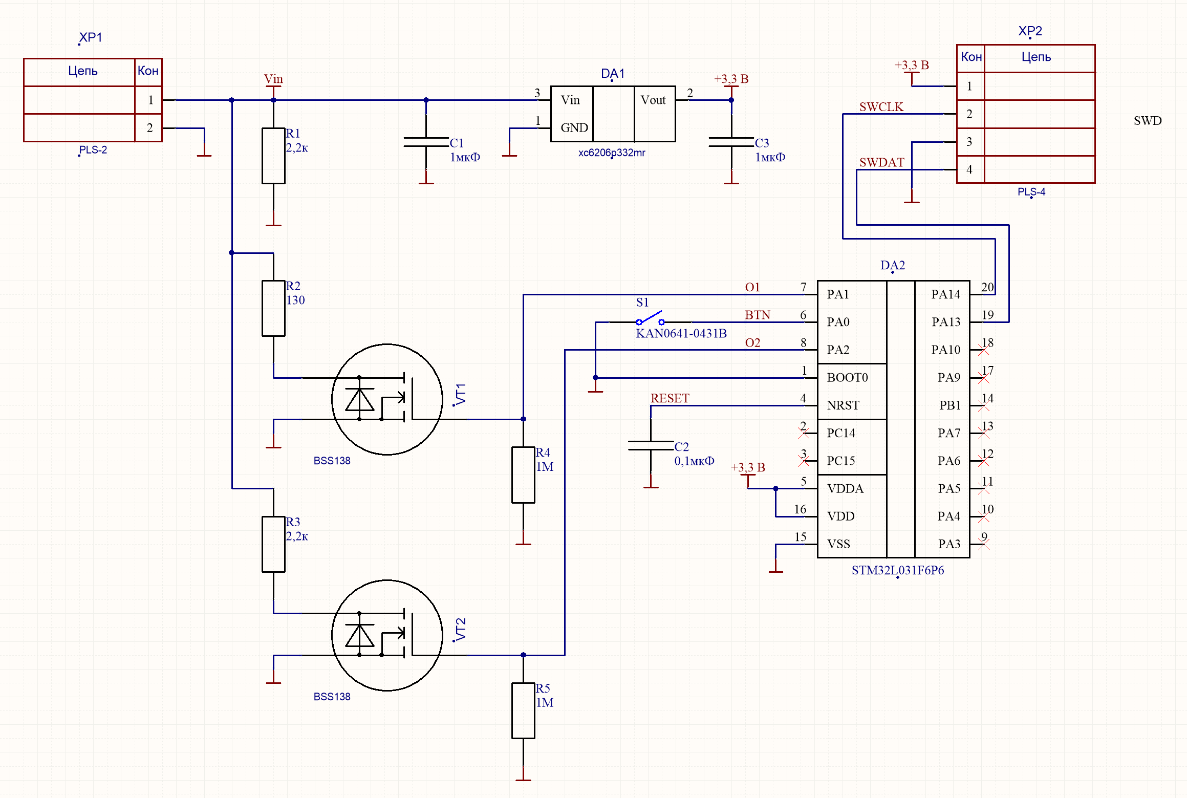
Once Seryozha, a programmer, approached me with a request to make a device for him in the car that emulates the sequential pressing of 2 virtual buttons when pressing one physical in the cruise control car control circuit (Ford Focus 2). The scheme of the standard control unit is as follows:

From the side of the control unit, this is a classic push-button input using an ADC. So the device’s task when pressing the hardware button is to press the ON and SET + button successively for ~ 0.2s. For ease of integration of the device, it was decided to power it from the upper resistor divider. Voltage at the terminals of 4.6 V connection without a connected button circuit. Since the device was planned to be made in the evening, I made a scheme without preliminary calculations from what was on the mounting table. The solution "in the forehead":
Sergei wrote the firmware, and the device worked fine on the car. At the moment when the board already wanted to pack someone from the depths of the office into the body of the steering-wheel switch shouted: “Why is it so difficult? Half of the details can be thrown out, and in general STM8 for such a task is the most ". And so it began ... The author of the idea volunteered to solder the layout “out of 3 details” (apparently anticipating an easy victory). I (guided by my own article about professional jealousy ) decided not to interfere with the flight of a young specialist, but only connected at a stage when everyone understood that a miracle did not happen.
The scheme proposed by my colleague was really simpler, but it worked only on the table:
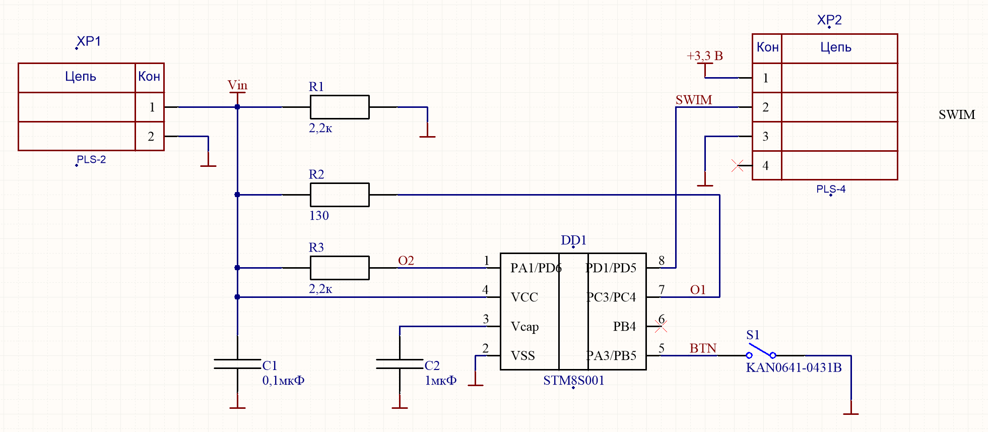
Errors were visible even at first glance, however, I decided to make the scheme work exactly on the STM8S001J3 MC.
In order to understand how to remake the scheme, we will conduct several measurements. The resistance of the upper resistor in the ADC divider is ~ 130 Ohms, and the voltage without a load is 4.6 V.
Then the button node layout is:

In this case, the operating voltage range of the MK STM8S001J3 is 2.95-5.5 V. It turns out that an attempt to press the SET + button leads to a voltage drop below the minimum and the MC is reset.
At this point, I propose to distract and discuss what an ideal MK is for this task and why it was not chosen. Usually for such crafts use what the developer knows how to work and what is at hand. For example, the microchip has PIC10F200 or ATtiny10 controllers in the SOT23-6 package with a supply voltage range of 2 (1.8) - 5.5 V. These chips do not require a voltage regulator (like STM32L031), but they will not restart when you press the SET + button (as STM8S001J3). In the strapping will be only 2 resistors and a capacitor. Beauty, but in the nomenclature of STMicro controllers with this power range is not. An attentive reader will rightly note that within the framework of such a task almost any controller can be mastered, but the lack of a familiar programming environment and debugging tools determine the choice.
Let's return to the scheme. To solve the problem of resetting the controller, we need energy to power the controller while pressing the SET + button. To estimate the amount of this energy, it is necessary to measure the current consumption (or see the documentation):

Almost 500 µA at best. This is a lot, but to make it clear I will give the calculation. For the accumulation of energy, we need a diode (VD1) and a capacitor (C1):

The drop on VD1 is 0.2 V, respectively, when the buttons are released, C1 will be charged up to 4.33 - 0.2 = 4.13 V. When you "press" the SET + button the voltage at the point Vin drops to 2.2 V, VD1 closes and the MK is powered by discharging C1.
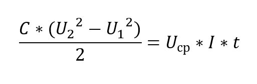
(For editing the error, thanks to VT100 and DenisHW )
In this expression, the energy stored in the capacitor on the left (when it is discharged from 4.13 to 3.1 V), on the right is the energy spent by the controller during the time t = 0.2 s. Then the capacitance of the capacitor:
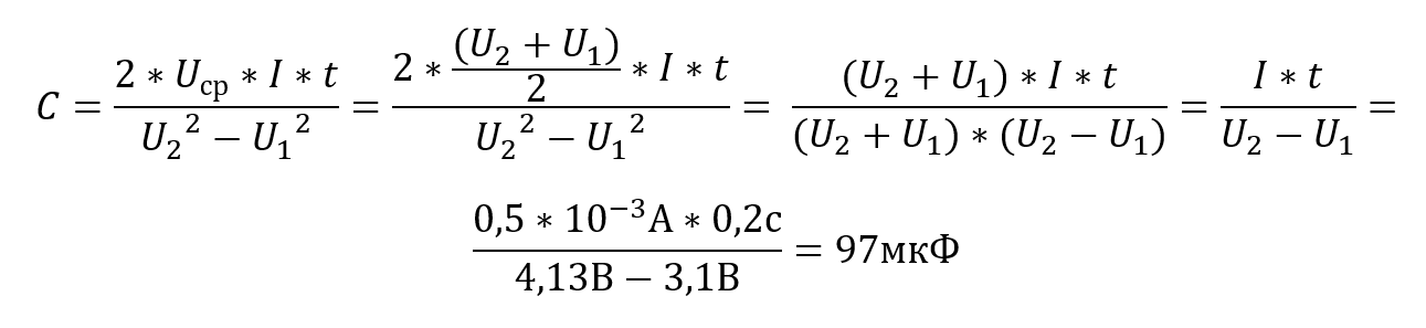
100 microfarads for this task is tolerable, but we will try to put the controller to sleep while pressing the button.
For this, the STM8 has Active Halt Mode:

By turning off MVR and Flash, we managed to get a current consumption of ~ 40 μA (this is significantly higher than the stated current, but this current is suitable for this task), and thanks to the AWU (auto wake up unit) you can easily set wake up after 256 ms after going to sleep. In this case, to ensure the operation of the controller, a capacitor with a capacity of only 10 microfarads is needed, but since it takes some time after the leg is clamped, the capacity of 47 microfarads turned out to be necessary and sufficient.
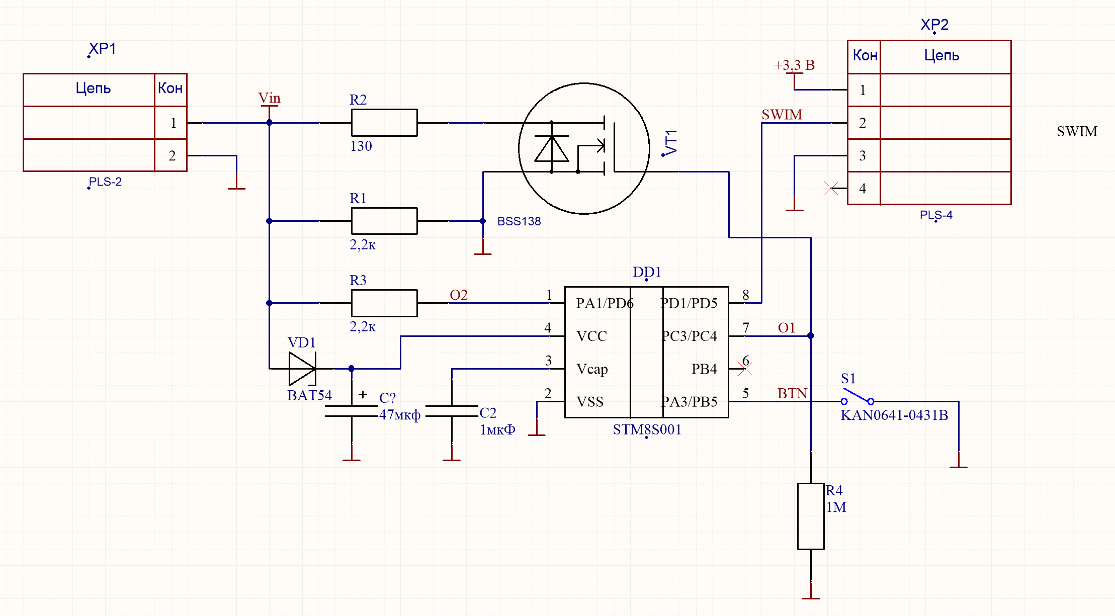
It seems that all problems are solved, but there is one more BUT. The current when the SET button is pressed + 18.4 mA is less than the current limit for the output, but the logic zero voltage will be around 0.7 V. This will lead to a drop in current through the resistor and will require either recalculating the resistance or using an external transistor according to the scheme with open drain. I chose the second option as more predictable in behavior. The final scheme took the form:
In this form, it has successfully earned and is being operated to this day.
Instead of conclusion
In this article I want to draw attention to the problem of how the developer is punished for an unnecessarily superficial or frivolous approach to the development of a simple (at first glance) device. On the other hand, I wanted to show how a non-optimal choice of the basic element base (in this case, MK) complicates the development process and the product itself for two main reasons:
Once Seryozha, a programmer, approached me with a request to make a device for him in the car that emulates the sequential pressing of 2 virtual buttons when pressing one physical in the cruise control car control circuit (Ford Focus 2). The scheme of the standard control unit is as follows:
From the side of the control unit, this is a classic push-button input using an ADC. So the device’s task when pressing the hardware button is to press the ON and SET + button successively for ~ 0.2s. For ease of integration of the device, it was decided to power it from the upper resistor divider. Voltage at the terminals of 4.6 V connection without a connected button circuit. Since the device was planned to be made in the evening, I made a scheme without preliminary calculations from what was on the mounting table. The solution "in the forehead":
Sergei wrote the firmware, and the device worked fine on the car. At the moment when the board already wanted to pack someone from the depths of the office into the body of the steering-wheel switch shouted: “Why is it so difficult? Half of the details can be thrown out, and in general STM8 for such a task is the most ". And so it began ... The author of the idea volunteered to solder the layout “out of 3 details” (apparently anticipating an easy victory). I (guided by my own article about professional jealousy ) decided not to interfere with the flight of a young specialist, but only connected at a stage when everyone understood that a miracle did not happen.
The scheme proposed by my colleague was really simpler, but it worked only on the table:
Errors were visible even at first glance, however, I decided to make the scheme work exactly on the STM8S001J3 MC.
In order to understand how to remake the scheme, we will conduct several measurements. The resistance of the upper resistor in the ADC divider is ~ 130 Ohms, and the voltage without a load is 4.6 V.
Then the button node layout is:
- when the buttons are released, the current in the circuit is 2 mA, the voltage at the input of the ADC is 4.33 V;
- when the button is pressed ON 3.7 mA, the voltage at the input of the ADC is 4.11 V;
- when the SET button is pressed + 18.4 mA, the input voltage of the ADC is 2.2 V.
In this case, the operating voltage range of the MK STM8S001J3 is 2.95-5.5 V. It turns out that an attempt to press the SET + button leads to a voltage drop below the minimum and the MC is reset.
At this point, I propose to distract and discuss what an ideal MK is for this task and why it was not chosen. Usually for such crafts use what the developer knows how to work and what is at hand. For example, the microchip has PIC10F200 or ATtiny10 controllers in the SOT23-6 package with a supply voltage range of 2 (1.8) - 5.5 V. These chips do not require a voltage regulator (like STM32L031), but they will not restart when you press the SET + button (as STM8S001J3). In the strapping will be only 2 resistors and a capacitor. Beauty, but in the nomenclature of STMicro controllers with this power range is not. An attentive reader will rightly note that within the framework of such a task almost any controller can be mastered, but the lack of a familiar programming environment and debugging tools determine the choice.
Let's return to the scheme. To solve the problem of resetting the controller, we need energy to power the controller while pressing the SET + button. To estimate the amount of this energy, it is necessary to measure the current consumption (or see the documentation):
Almost 500 µA at best. This is a lot, but to make it clear I will give the calculation. For the accumulation of energy, we need a diode (VD1) and a capacitor (C1):
The drop on VD1 is 0.2 V, respectively, when the buttons are released, C1 will be charged up to 4.33 - 0.2 = 4.13 V. When you "press" the SET + button the voltage at the point Vin drops to 2.2 V, VD1 closes and the MK is powered by discharging C1.
(For editing the error, thanks to VT100 and DenisHW )
In this expression, the energy stored in the capacitor on the left (when it is discharged from 4.13 to 3.1 V), on the right is the energy spent by the controller during the time t = 0.2 s. Then the capacitance of the capacitor:
100 microfarads for this task is tolerable, but we will try to put the controller to sleep while pressing the button.
For this, the STM8 has Active Halt Mode:
By turning off MVR and Flash, we managed to get a current consumption of ~ 40 μA (this is significantly higher than the stated current, but this current is suitable for this task), and thanks to the AWU (auto wake up unit) you can easily set wake up after 256 ms after going to sleep. In this case, to ensure the operation of the controller, a capacitor with a capacity of only 10 microfarads is needed, but since it takes some time after the leg is clamped, the capacity of 47 microfarads turned out to be necessary and sufficient.
It seems that all problems are solved, but there is one more BUT. The current when the SET button is pressed + 18.4 mA is less than the current limit for the output, but the logic zero voltage will be around 0.7 V. This will lead to a drop in current through the resistor and will require either recalculating the resistance or using an external transistor according to the scheme with open drain. I chose the second option as more predictable in behavior. The final scheme took the form:
In this form, it has successfully earned and is being operated to this day.
Instead of conclusion
In this article I want to draw attention to the problem of how the developer is punished for an unnecessarily superficial or frivolous approach to the development of a simple (at first glance) device. On the other hand, I wanted to show how a non-optimal choice of the basic element base (in this case, MK) complicates the development process and the product itself for two main reasons:
- The need to adjust the choice of technical solutions to the skills of the programmer.
- Impossibility to embrace the whole range of possible components, suitable for the task, to choose from them the “most”. These factors, most often, explain the fact that many devices (household, commercial, special) work normally, but they are not made the way you would have done it.