Quagga routing table
By the nature of my activity, I am involved in network design and network equipment setup. At some point in time, I wanted to find out how the network devices are arranged, which were always black boxes for me that magically implement network protocols. Since devices from vendors such as Cisco or Juniper are closed and not available for any study, my choice fell on the Quagga program - an open source router that is widely used in real life and quite successfully handles OSPF and BGP protocols. Armed with the sources of Quagga, I began to research. In this article I want to tell how the routing table in Quagga is arranged, what structures and algorithms are used to implement it.
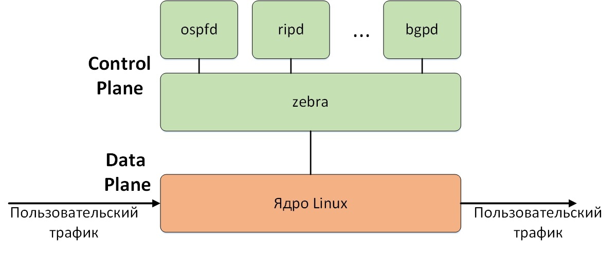
First, a few words about the general architecture of Quagga. Quagga consists of several separate programs, or daemons, each of which performs a specific function. For example, the ospfd daemon implements OSPF, and bgpd implements BGP. The central role in Quagga is played by the zebra daemon. One of its main roles is to obtain routing information from demons that implement specific protocols and select the best routes received from various sources. After that, the best routes are transferred to the Linux kernel, which actually transfers user traffic (we believe that Quagga is installed on Linux). Thus, the classic separation of the “intelligence” of the router (Control Plane) and the transmission of user traffic (Data Plane) is implemented. In our case, Quagga acts as the Control Plane, and the Linux kernel as the Data Plane.
Each individual route in the routing table can be represented as a prefix (usually indicated as the IP address and prefix length, for example 192.168.0.0/24), which are associated with different routing information: next-hop, administrative distance, metric, protocol that reported the route etc. A routing table is simply a multitude of such prefixes with associated additional information. The zebra daemon stores all routes that were passed to it or were configured in zebra itself. For example, if you configured a static route 192.168.0.0/24 with next-hop 1.1.1.1, and also received a route with the same prefix from the ospfd daemon and next-hop 2.2.2.2, then zebra will store both of these routes and show them in the output of the show ip route command. Storing all routes allows you to quickly choose a new best route, if for some reason the current best route has ceased to exist. For example, in our example, after deleting the static route, zebra immediately selects the best OSPF route without any call to the ospfd daemon. Routes for a specific prefix are stored as a linked list, as shown in the figure (in this case, for the prefix 192.168.0.0/24). The best route is marked in green.
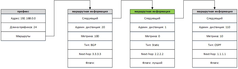
Upon receipt of the next route, its route information is added to the top of the linked list, after which the procedure of sequential viewing of all routes for a given prefix and choosing the best one starts. The best route (subject to next-hop validity) is the route with the smallest administrative distance. Since, by default, routes from different protocols have different administrative distances (for example, OSPF has 110, and a static route has 1), it is the administrative distance that is the determining criterion for choosing the best route. If the settings are such that the same administrative distance is set for different routes, then the route with the smallest metric is the best. If the routes have the same administrative distance and metric, then the route will be the best, which is closer to the end of the list, i.e. one that was added before.
When deleting a route, this route is removed from the list of routes for a given prefix, and the procedure for selecting the best route starts in the same way. For example, after deleting a static route, the picture will look as follows:
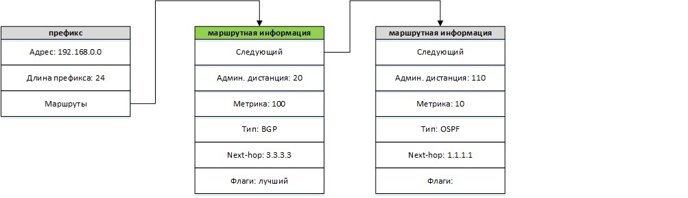
After choosing the best route, information about it is transmitted to the Linux kernel.
As a rule, there are not many routes for one prefix and it does not take much time to look through them all to choose the best one. A much more difficult task is to find the prefix itself when adding or removing a route. There can be a lot of different prefixes in the routing table - thousands and tens of thousands, and a simple sequential search of all prefixes to find the right one will be extremely inefficient. For faster and more efficient searches, all prefixes in the routing table are stored as a structure called a compact trie or compressed binary prefix tree.
In the future, prefixes will be more convenient to represent in binary form, indicating only the first bits, in an amount equal to the length of the prefix. The remaining bits of the prefix are 0 and are not important for the search. For example, the prefix 10.0.0.0/8 in binary will look like 00001010, the prefix 128.0.0.0/1 will look like 1, 128.0.0.0/2 as 10, etc.
What is a trie or prefix tree and how it works can be read, for example, here . For our purposes, the easiest way to understand it is by example. For example, we have prefixes 1, 111, 010, 0110000. These prefixes will be organized as the following prefix tree:
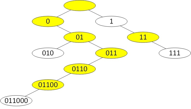
White nodes correspond to the prefixes that interest us. The yellow nodes are intermediate and serve to properly organize the structure of the tree. The top node is the root of the tree and corresponds to the prefix 0.0.0.0/0. The search for the desired prefix is performed as follows. The search begins with the root of the tree. Then the first bit of the desired prefix is checked. If the first bit is 0, then go down to the left child. If the first bit is 1, then to the right child. Then we repeat this procedure for the second bit of the desired prefix, then for the third, etc. until we get to the desired prefix or make sure that it is not there. In the absence of the necessary prefix, it is added to the tree in the appropriate place. It can be seen that the number of accesses to the tree is equal to the length of the desired prefix and for the longest IPv4 prefix is 32. Strictly speaking, it is not necessary to store the prefix itself in each node of the tree, since it is uniquely determined by the location of the node, but I indicated it for clarity. In addition, in the real Quagga structure, the prefix is actually stored in each node of the tree.
A compressed prefix tree differs from the usual tree in that it optimizes long chains without branching. For our example, a compressed prefix tree will look like this:
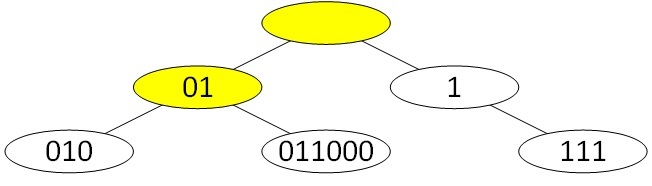
Now when searching for a prefix in the current node, we check whether the first n bits of the desired prefix match with the prefix bits in the node, where n is the length of the prefix in the node. If the bits match, then we look in the desired prefix for the n + 1st bit and depending on whether it is 0 or 1, we go down to the left or right child element.
For example, the prefix 011000 will be searched as follows. We start as usual with the root of the tree. The root in our case contains a prefix of length 0, so we check the first bit of the desired prefix. Since it is 0, we go down to the left child element and get to the node with the prefix 01. Here we compare the desired prefix with the prefix in the current node, that is, whether the first 2 bits of the prefix 011000 coincide with the prefix 01. Since the bits match, then move on and check the 3rd bit of the desired prefix. The third bit is 1, so we go down to the right child and get into the 011000 prefix we need. To find the prefix, we needed three calls to the tree instead of seven in the case of an uncompressed tree. If at some stage it turned out that the first n bits of the prefix in the node do not coincide with the bits of the desired prefix, then this means
In Quagga, the prefix is stored as the ip address and prefix length. In this case, only the first n-bits are significant, where n is the prefix length, and the rest are 0 and do not participate in the search for the desired prefix. For example, the prefix 192.168.1.0/24 looks like:
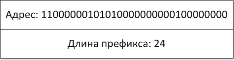
For clarity, I will display it as follows:
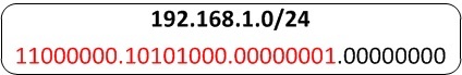
Here, at the top, I indicate the usual form of the prefix in decimal form, and below is its binary representation, with the number of bits equal to the length of the prefix marked in red. In such designations, a routing table consisting of the prefixes 0.0.0.0/0, 10.0.0.0/8, 172.16.0.0/16, 192.168.0.0/24, 192.168.1.0/24, 192.168.2.0/24 will look like this:
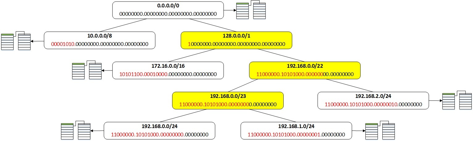
For example, when searching for the prefix 192.168.1.0/24, its 1st, 2nd, 23rd, and 24th bits are sequentially checked to find its location in the tree. Each of our prefixes also indicates the corresponding routing information. The prefixes highlighted in yellow are intermediate and there is no routing information for them.
In conclusion, I would like to tell you how the images are displayed when typing the show ip route command. To display the routes, you must somehow sort through all the prefixes in the tree. This procedure is called tree traversal and can be implemented in various ways. Quagga uses a workaround called pre-ordered, which is easiest to define recursively:
The same rules are used to bypass subtrees. For the routing table we constructed above, prefix bypass will look like this. First we take the top of the tree, i.e. prefix 0.0.0.0/0. Then we go around the left subtree. It consists of a single prefix 10.0.0.0/8. Then we
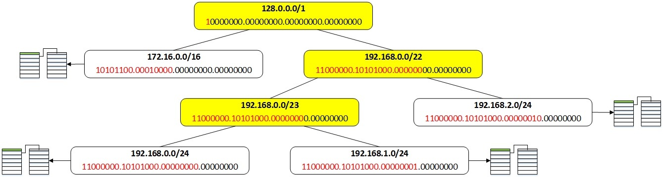
go around the right subtree, which we will display in the figure: To bypass it, apply the same rules: first we take its root, i.e. 128.0.0.0/1 prefix, then bypass its left subtree, i.e. prefix 172.16.0.0/16, then the right subtree, shown in the figure:
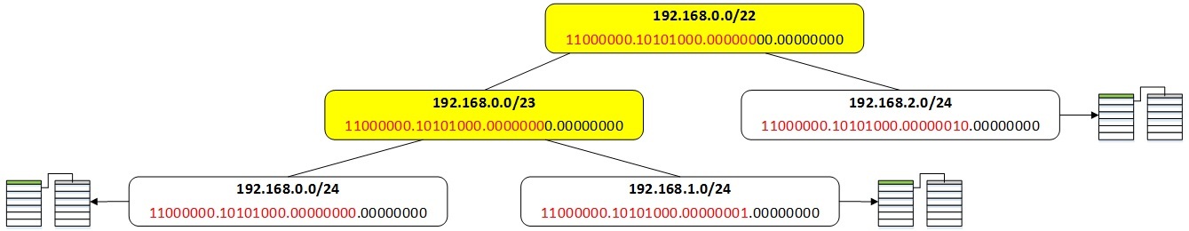
Next, take the top of this subtree, i.e. prefix 192.168.0.0/22, bypass its left subtree, getting the prefixes 192.168.0.0/23, 192.168.0.0/24 and 192.168.1.0/24, and its right subtree, consisting of the prefix 192.168.2.0/24.
Thus, we will get the prefixes in the following order: 0.0.0.0/0, 10.0.0.0/8, 128.0.0.0/1, 172.16.0.0/16, 192.168.0.0/22, 192.168.0.0/23, 192.168.0.0/ 24, 192.168.1.0/24, 192.168.2.0/24. The prefixes 128.0.0.0/1, 192.168.0.0/22 and 192.168.0.0/23 are service ones and are not shown when the routing table is displayed. The remaining prefixes will be displayed in the order: 0.0.0.0/0, 10.0.0.0/8, 172.16.0.0/16, 192.168.0.0/24, 192.168.1.0/24, 192.168.2.0/24.
In conclusion, I give a list of Quagga source files where the above structures and algorithms are implemented:
Quagga sources can be downloaded from here: download.savannah.gnu.org/releases/quagga . I took version 0.99.24.
Structures and functions for working with prefixes are located in the lib / prefix.c file.
Structures and functions for working with the prefix tree are in the file lib / table.c
Structures and functions for working with the routing information are in the file zebra / zebra_rib.c
Quagga Architecture
First, a few words about the general architecture of Quagga. Quagga consists of several separate programs, or daemons, each of which performs a specific function. For example, the ospfd daemon implements OSPF, and bgpd implements BGP. The central role in Quagga is played by the zebra daemon. One of its main roles is to obtain routing information from demons that implement specific protocols and select the best routes received from various sources. After that, the best routes are transferred to the Linux kernel, which actually transfers user traffic (we believe that Quagga is installed on Linux). Thus, the classic separation of the “intelligence” of the router (Control Plane) and the transmission of user traffic (Data Plane) is implemented. In our case, Quagga acts as the Control Plane, and the Linux kernel as the Data Plane.
Route information storage
Each individual route in the routing table can be represented as a prefix (usually indicated as the IP address and prefix length, for example 192.168.0.0/24), which are associated with different routing information: next-hop, administrative distance, metric, protocol that reported the route etc. A routing table is simply a multitude of such prefixes with associated additional information. The zebra daemon stores all routes that were passed to it or were configured in zebra itself. For example, if you configured a static route 192.168.0.0/24 with next-hop 1.1.1.1, and also received a route with the same prefix from the ospfd daemon and next-hop 2.2.2.2, then zebra will store both of these routes and show them in the output of the show ip route command. Storing all routes allows you to quickly choose a new best route, if for some reason the current best route has ceased to exist. For example, in our example, after deleting the static route, zebra immediately selects the best OSPF route without any call to the ospfd daemon. Routes for a specific prefix are stored as a linked list, as shown in the figure (in this case, for the prefix 192.168.0.0/24). The best route is marked in green.
Upon receipt of the next route, its route information is added to the top of the linked list, after which the procedure of sequential viewing of all routes for a given prefix and choosing the best one starts. The best route (subject to next-hop validity) is the route with the smallest administrative distance. Since, by default, routes from different protocols have different administrative distances (for example, OSPF has 110, and a static route has 1), it is the administrative distance that is the determining criterion for choosing the best route. If the settings are such that the same administrative distance is set for different routes, then the route with the smallest metric is the best. If the routes have the same administrative distance and metric, then the route will be the best, which is closer to the end of the list, i.e. one that was added before.
When deleting a route, this route is removed from the list of routes for a given prefix, and the procedure for selecting the best route starts in the same way. For example, after deleting a static route, the picture will look as follows:
After choosing the best route, information about it is transmitted to the Linux kernel.
Prefix storage
As a rule, there are not many routes for one prefix and it does not take much time to look through them all to choose the best one. A much more difficult task is to find the prefix itself when adding or removing a route. There can be a lot of different prefixes in the routing table - thousands and tens of thousands, and a simple sequential search of all prefixes to find the right one will be extremely inefficient. For faster and more efficient searches, all prefixes in the routing table are stored as a structure called a compact trie or compressed binary prefix tree.
In the future, prefixes will be more convenient to represent in binary form, indicating only the first bits, in an amount equal to the length of the prefix. The remaining bits of the prefix are 0 and are not important for the search. For example, the prefix 10.0.0.0/8 in binary will look like 00001010, the prefix 128.0.0.0/1 will look like 1, 128.0.0.0/2 as 10, etc.
What is a trie or prefix tree and how it works can be read, for example, here . For our purposes, the easiest way to understand it is by example. For example, we have prefixes 1, 111, 010, 0110000. These prefixes will be organized as the following prefix tree:
White nodes correspond to the prefixes that interest us. The yellow nodes are intermediate and serve to properly organize the structure of the tree. The top node is the root of the tree and corresponds to the prefix 0.0.0.0/0. The search for the desired prefix is performed as follows. The search begins with the root of the tree. Then the first bit of the desired prefix is checked. If the first bit is 0, then go down to the left child. If the first bit is 1, then to the right child. Then we repeat this procedure for the second bit of the desired prefix, then for the third, etc. until we get to the desired prefix or make sure that it is not there. In the absence of the necessary prefix, it is added to the tree in the appropriate place. It can be seen that the number of accesses to the tree is equal to the length of the desired prefix and for the longest IPv4 prefix is 32. Strictly speaking, it is not necessary to store the prefix itself in each node of the tree, since it is uniquely determined by the location of the node, but I indicated it for clarity. In addition, in the real Quagga structure, the prefix is actually stored in each node of the tree.
A compressed prefix tree differs from the usual tree in that it optimizes long chains without branching. For our example, a compressed prefix tree will look like this:
Now when searching for a prefix in the current node, we check whether the first n bits of the desired prefix match with the prefix bits in the node, where n is the length of the prefix in the node. If the bits match, then we look in the desired prefix for the n + 1st bit and depending on whether it is 0 or 1, we go down to the left or right child element.
For example, the prefix 011000 will be searched as follows. We start as usual with the root of the tree. The root in our case contains a prefix of length 0, so we check the first bit of the desired prefix. Since it is 0, we go down to the left child element and get to the node with the prefix 01. Here we compare the desired prefix with the prefix in the current node, that is, whether the first 2 bits of the prefix 011000 coincide with the prefix 01. Since the bits match, then move on and check the 3rd bit of the desired prefix. The third bit is 1, so we go down to the right child and get into the 011000 prefix we need. To find the prefix, we needed three calls to the tree instead of seven in the case of an uncompressed tree. If at some stage it turned out that the first n bits of the prefix in the node do not coincide with the bits of the desired prefix, then this means
In Quagga, the prefix is stored as the ip address and prefix length. In this case, only the first n-bits are significant, where n is the prefix length, and the rest are 0 and do not participate in the search for the desired prefix. For example, the prefix 192.168.1.0/24 looks like:
For clarity, I will display it as follows:
Here, at the top, I indicate the usual form of the prefix in decimal form, and below is its binary representation, with the number of bits equal to the length of the prefix marked in red. In such designations, a routing table consisting of the prefixes 0.0.0.0/0, 10.0.0.0/8, 172.16.0.0/16, 192.168.0.0/24, 192.168.1.0/24, 192.168.2.0/24 will look like this:
For example, when searching for the prefix 192.168.1.0/24, its 1st, 2nd, 23rd, and 24th bits are sequentially checked to find its location in the tree. Each of our prefixes also indicates the corresponding routing information. The prefixes highlighted in yellow are intermediate and there is no routing information for them.
Prefix tree traversal
In conclusion, I would like to tell you how the images are displayed when typing the show ip route command. To display the routes, you must somehow sort through all the prefixes in the tree. This procedure is called tree traversal and can be implemented in various ways. Quagga uses a workaround called pre-ordered, which is easiest to define recursively:
- First we take the top of the tree.
- Then we go around the left subtree.
- Then we go around the right subtree.
The same rules are used to bypass subtrees. For the routing table we constructed above, prefix bypass will look like this. First we take the top of the tree, i.e. prefix 0.0.0.0/0. Then we go around the left subtree. It consists of a single prefix 10.0.0.0/8. Then we
go around the right subtree, which we will display in the figure: To bypass it, apply the same rules: first we take its root, i.e. 128.0.0.0/1 prefix, then bypass its left subtree, i.e. prefix 172.16.0.0/16, then the right subtree, shown in the figure:
Next, take the top of this subtree, i.e. prefix 192.168.0.0/22, bypass its left subtree, getting the prefixes 192.168.0.0/23, 192.168.0.0/24 and 192.168.1.0/24, and its right subtree, consisting of the prefix 192.168.2.0/24.
Thus, we will get the prefixes in the following order: 0.0.0.0/0, 10.0.0.0/8, 128.0.0.0/1, 172.16.0.0/16, 192.168.0.0/22, 192.168.0.0/23, 192.168.0.0/ 24, 192.168.1.0/24, 192.168.2.0/24. The prefixes 128.0.0.0/1, 192.168.0.0/22 and 192.168.0.0/23 are service ones and are not shown when the routing table is displayed. The remaining prefixes will be displayed in the order: 0.0.0.0/0, 10.0.0.0/8, 172.16.0.0/16, 192.168.0.0/24, 192.168.1.0/24, 192.168.2.0/24.
Conclusion
In conclusion, I give a list of Quagga source files where the above structures and algorithms are implemented:
Quagga sources can be downloaded from here: download.savannah.gnu.org/releases/quagga . I took version 0.99.24.
Structures and functions for working with prefixes are located in the lib / prefix.c file.
Structures and functions for working with the prefix tree are in the file lib / table.c
Structures and functions for working with the routing information are in the file zebra / zebra_rib.c