Unity: how we created a house generator for AssetStore or a return to the Khrushchevs

The reason for writing this article was this publication about the "Khrushchev", which raised the interesting topic for me of programmed mesh generation in Unity .
My article is not intended for those who have long been working on Unity, it is unlikely that there will be anything new for people familiar with the intricacies of Unity. Also, for completely newcomers, unobvious “difficulties” are possible here and why you need to invent something when everything is in the editor. Our audience is most suitable for developers who are already able to do something in Unity, but they have not yet solved the problem of dynamically changing meshes in the editor. Also, some of us may benefit from our experience with the inspector.
The author does not claim to have absolute knowledge of the subject area, I just want to tell in my own words the solution to some of the tasks that appeared when creating the asset.
After reading the above article, I immediately realized that this is what we need for our project. Initially, we were going to create houses from exported fbx files. Of course, we did not do it one-on-one as described, we pushed off the basic idea and immediately set ourselves the task: editing and viewing buildings directly in the Unity editor without switching to the running game mode. As a consequence of the previous idea, it turned out to fit all the building settings in one script and, as a result, in the object inspector it turned out to edit the entire structure in one place.
Small digression
I'll start with self-irony. Our small team some time ago took up the development of games for mobile platforms. Starting with the ambitious task of creating our own game engine, we set to work. According to my own experience in developing other areas of activity and reading books about creating game engines, it was decided to write everything in pure si ( PureC ) . Several key basic subsystems of its engine were implemented: optimized memory manager; graphic renderer; a hierarchy of objects based on the component approach ( publication on the hub ) to the creation of composite models; tied LUAfor the ability to script created games; implemented the ability to store everything and everything (including scripts in Lua) and more in a local database based on SQLite . After quite a long time of implementing all of the above and mastering the interfaces provided by OpenGL, we came to the disappointing conclusion: we can create a full-fledged engine, but very soon.
Transition to Unity
Naturally, in parallel with creating our own engine, we were interested in the achievements of the gaming industry. We were very attracted to the Unreal Engine , but the minimal project of 30 ... 45MB for mobile platforms immediately cooled us down, and we decided to look for other solutions, Shiva more or less came up , after a short study of this engine, we decided to look for more options. Finally, we recently tried our hand at Unity. The Unity C # syntax was partially mastered, but it was rather difficult to get used to the fact that, thanks to the garbage collection system ( GC ), it was not always necessary to free up created and no longer needed resources.
Selected topics for work
Before describing further work, I’ll immediately tell you about the limitations: I started studying Unity 5 right away, that is, all examples should work in the 5th version of Unity, for the previous 4th, and even more so the 3rd version, I can not give any guarantees. From my own experience I can say that some of the lessons / scripts that I came across for the 4th version turned out to be run on the 5th, some required reformatting to the new version and started successfully, and some failed to start, I had to change the command syntax . I do not know anything about backward compatibility of versions (a small addition: before publishing the asset, I successfully tested the scripts listed below on Unity 4.5.0).
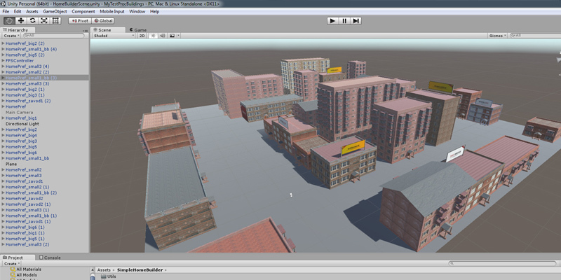
To visually fill the game, it was decided to saturate the surrounding background with various buildings. I wanted to immediately see the approximate appearance of the buildings in the editor. In order to be able to "run" the script directly in the editor, you must write the line [ExecuteInEditMode] before the class inherited from MonoBehaviour, ie create the MyTest.cs script in the project and modify it according to the following template:
using UnityEngine;
[ExecuteInEditMode]
publicclassMyTest : MonoBehaviour {
    //здесь всё как обычно,
    //идет перечисление
    //полей и методов
}
When changing any field in the inspector, the script method (if implemented) Update () will be called. In order to save on the size of the scripts collected for the game, this method can be "escaped" with a pair of #if UNITY_EDITOR ... #endif directives, thus an approximate template of the script that can be changed directly in the inspector emerges for the component:
using UnityEngine;
[ExecuteInEditMode]
publicclassMyTest : MonoBehaviour {
    publicint i=10;
#if UNITY_EDITOR
    voidUpdate () {
        Debug.Log ("Update");
    }
#endif
}
Attach this script to any component on the stage and change the value of the i field in the inspector, the console will immediately display “Update” (more precisely, the number of “Update” messages will increase), the rest of the time the script will “wait” for changes in public fields.
It should be noted that if there are a large number of components on the scene with this script, the scene will noticeably slow down. To get rid of this, you need to move the change processor in the inspector to a script in a special Editor folder. The contents of this folder will not fall into the finished project. Let's create the Editor folder, and in it the script MyTestInspector.cs:
using UnityEngine;
using UnityEditor;
using System.Collections;
[CustomEditor(typeof(MyTest))]
publicclassMyTestInspector : Editor {
    //пишем свой обработчик инспектора
    publicoverridevoidOnInspectorGUI()
    {
        //рисуем инспектор по умолчанию
        DrawDefaultInspector ();
        //получаем ссылку на выделенный объект
        MyTest mt = target as MyTest;
        //выполняем метод объекта,
        //реагирующий на изменения в инспекторе
        mt.DoRefresh();
    }
}
Let's look at the modified MyTest script:
using UnityEngine;
[ExecuteInEditMode]
publicclassMyTest : MonoBehaviour {
    publicint i=10;
    publicvoidDoRefresh () {
        Debug.Log ("Update");
    }
}
Inspector setup for more convenient work
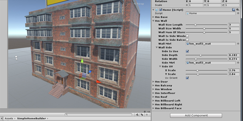
After studying the official information and googling, we first settled on a variant that provided for the redrawing of public properties in the inspector and the reaction to their changes by the appropriate methods in the script, but then it was decided to split the source data for editing into interconnected data structures that are easy to operate with without losing in approximately 130 simultaneously visible settings for building the building. After that, the need for a "personal inspector" disappeared. However, we hope to return to this approach in the future when creating and editing components. If anyone is interested, then I can give links: here and here .
Some subtleties of creating an interface
With the usual creation of a public variable of type int or float, for example, this:
publicint iterator=2;
publicfloat dx=0.5f;
In the inspector, they are displayed as simple editing fields, with frequent changes of these values during the work, it is terribly boring to constantly get the mouse cursor into the fields, enter meaningful numbers that differ little from each other, and look at the changes received, a different approach is much more convenient. When declaring fields immediately before the variable (line above), indicate the valid range for the entered values:
[Range(-10, 10)]
publicint iterator=2;
[Range(0.0f, 1.0f)]
publicfloat dx=0.5f;
After such an addition before the variables, in the inspector it is enough to move the slider to smoothly or abruptly change the value.
In order not to show all the fields in the script at the same time, and we have about 130 of them, you can resort to grouping the values strongly related to each other into one class, and declare this class to be a public field in the script. In order to be able to save field changes in separate instances of classes and show fields in the inspector, it is necessary to write the line [System.Serializable] before declaring the class (again the line above), as a result we get:
[System.Serializable]
publicclassLeftRightSide {
    [Range(0, 100)]
    publicint leftSide=3;
    [Range(0, 100)]
    publicint rightSide=20;
}
After you declare this class as a public field in your script, a hidden / expandable block of fields will appear in the inspector for editing the contents of the class described above. A hierarchical nesting of various classes into each other is possible and it is limited only by common sense. Such a simple technique allows you, firstly: to group related data, and secondly: it simplifies navigation in the inspector. We describe the entire script:
using UnityEngine;
[ExecuteInEditMode]
publicclassMyTest : MonoBehaviour {
    public LeftRightSide leftRight=new LeftRightSide();
    publicvoidDoRefresh () {
        Debug.Log ("Update");
    }
}
[System.Serializable]
publicclassLeftRightSide {
    [Range(0, 100)]
    publicint leftSide;
    [Range(0, 100)]
    publicint rightSide;
}
Editable directly in the mesh editor
Preparing components for drawing a mesh. In order to be able to edit and show the mesh, you can use the features of the editor, for example: create an empty object on the stage, then add MeshFilter and MeshRenderer to it through the menu items Component-> Mesh-> Mesh Filter and Component-> Mesh-> Mesh Renderer respectively. The first component is responsible for the "internal" mesh geometry, the second is associated with the drawing of the mesh on the screen. There is another, more reliable way to add these components. When creating a script, you must instruct you to add the above two components if they are not on the component to which the script is attached. To do this, write the string [RequireComponent (typeof (MeshFilter), typeof (MeshRenderer))] before declaring a descendant class of MonoBehaviour.
using UnityEngine;
using System.Collections;
[RequireComponent(typeof(MeshFilter), typeof(MeshRenderer))]
[ExecuteInEditMode]
publicclassMyTest : MonoBehaviour {
    //...
}
A bit of theory (those who know how to work with meshes in Unity may skip this section)
To display something in the component’s mesh, you need to fill the mesh with the required data. The minimum of which consists of a set of vertices and so-called facets (this name has synonyms, for example: triangles, faces, facets, an array of indices), that is, rules for linking vertices to each other. Additionally, the possibility of drawing textures will be considered, that is, it will be necessary to use uv coordinates. Normals will also be shown briefly. Immediately make a reservation, here I consider only the "classical" work of shaders, without considering the operation of the particle system, the mesh mode of operation, and more. That is, the mode of drawing triangles based on the vertices and the rules of their "bundle" will be considered. In general, a detailed discussion of this topic, i.e. meshes, shaders, bundles of vertices, facets, normals, texture coordinates,
Being able to draw a triangle, you can draw an arbitrarily complex figure by combining triangles with each other. For example, for a square, rhombus, parallelepiped, trapezoid, and generally a quadrangle, two triangles are sufficient. To draw more complex shapes you need more triangles, but the principle will not change. That is, the minimum and sufficient primitive for drawing everything else, we agree to consider a triangle.
I’ll briefly mention shaders: shaders are specially written and compiled programs that draw triangles according to certain rules. In fact, everything is somewhat more complicated, but for brevity we will accept this interpretation. I’ll just mention that when drawing another triangle, the shader does not know anything about neighboring triangles.
The memory in the computer is linear, and wherever there is a large / compound data block (that is, a structure, class, array, etc.), its contents are immediately behind each other, and access to its elements is best arranged linearly as well. And since the mesh is a complex structure that can contain quite large volumes of different, but united by the type of specific data, then the management of this data will also be correctly organized by linear access. That is, you need to create and populate arrays with the appropriate data, and then attach these arrays to the mesh.
I will list some data types we need to build meshes:
Vertices (vertices) - consist of an array of data of type Vector3, that is, of a structure containing three consecutive data of type float, which are nothing more than the spatial coordinates of one vertex along the x, y and z axes.
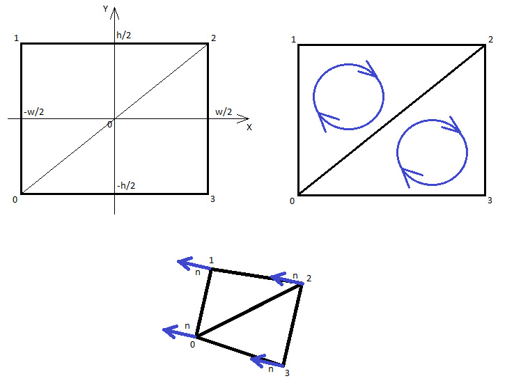
Vertex indices or facets (triangles) - consist of an array of int data type, but here you need to consider that integers must be grouped by 3 into one triangle. Consider this point in more detail, the fact is that to describe one triangle (that is, a minimally drawn primitive), you need to specify 3 vertex indexes. The first three numbers determine the drawing of the first triangle, the second three - the second, etc. It is also important to mention the order of traversal of the vertices in the triangle. If you list vertices (that is, vertex indices) clockwise, the triangle “looks at you”, that is, you see it, otherwise the triangle will not draw and you will not see it, but if you visually “go around” it from the opposite side, then it will become visible to you (that is, from a new angle, the enumeration of the vertices will “change” and will be clockwise).
Normals - consist of an array of data of type Vector3, it is an array of "perpendiculars" to the vertices, the dimensions of the array of normals and the array of vertices are the same. The absolute length of each normal vector is equal to unity, in fact, the "rotation angle" of the vertex is formed. Why are these normals necessary? They are needed in order to correctly take into account the lighting of the triangle. Knowing the angles between the normal, the beam of the light source and the eye of the observer, one can calculate the illumination. Normals are created and calculated not for triangles, as you might assume, but for vertices individually. If you set the normal only to a triangle, then the shader will not know how the normal should change from triangle to triangle (because the shader does not know anything about neighboring triangles), from this the drawn shape will look albeit illuminated, but very "angular." The fact is that the shader, when processing each triangle, uniformly changes some parameters between the vertices from one to another, including the normal to the vertices. Thanks to this, a smooth change in illumination is obtained even within the same triangle. If the normals to the vertices of the triangle diverge from each other, then the triangle will look “convex”, if the normals converge, then the triangle will be “concave”, if the normals are parallel, the triangle will be flat. Neighboring triangles will be built on the same principle, their corresponding vertices will coincide with the normals, and if the triangles are at different, but not very different angles, then the transition between the triangles will be smooth, and the border between them will be indistinguishable. The fact is that the shader, when processing each triangle, uniformly changes some parameters between the vertices from one to another, including the normal to the vertices. Thanks to this, a smooth change in illumination is obtained even within the same triangle. If the normals to the vertices of the triangle diverge from each other, then the triangle will look “convex”, if the normals converge, then the triangle will be “concave”, if the normals are parallel, the triangle will be flat. Neighboring triangles will be built on the same principle, their corresponding vertices will coincide with the normals, and if the triangles are at different, but not very different angles, then the transition between the triangles will be smooth, and the border between them will be indistinguishable. The fact is that the shader, when processing each triangle, uniformly changes some parameters between the vertices from one to another, including the normal to the vertices. Thanks to this, a smooth change in illumination is obtained even within the same triangle. If the normals to the vertices of the triangle diverge from each other, then the triangle will look “convex”, if the normals converge, then the triangle will be “concave”, if the normals are parallel, the triangle will be flat. Neighboring triangles will be built on the same principle, their corresponding vertices will coincide with the normals, and if the triangles are at different, but not very different angles, then the transition between the triangles will be smooth, and the border between them will be indistinguishable. uniformly changes some parameters between vertices from one to another, including the normal to the vertices. Thanks to this, a smooth change in illumination is obtained even within the same triangle. If the normals to the vertices of the triangle diverge from each other, then the triangle will look “convex”, if the normals converge, then the triangle will be “concave”, if the normals are parallel, the triangle will be flat. Neighboring triangles will be built on the same principle, their corresponding vertices will coincide with the normals, and if the triangles are at different, but not very different angles, then the transition between the triangles will be smooth, and the border between them will be indistinguishable. uniformly changes some parameters between vertices from one to another, including the normal to the vertices. Thanks to this, a smooth change in illumination is obtained even within the same triangle. If the normals to the vertices of the triangle diverge from each other, then the triangle will look “convex”, if the normals converge, then the triangle will be “concave”, if the normals are parallel, the triangle will be flat. Neighboring triangles will be built on the same principle, their corresponding vertices will coincide with the normals, and if the triangles are at different, but not very different angles, then the transition between the triangles will be smooth, and the border between them will be indistinguishable. Thanks to this, a smooth change in illumination is obtained even within the same triangle. If the normals to the vertices of the triangle diverge from each other, then the triangle will look “convex”, if the normals converge, then the triangle will be “concave”, if the normals are parallel, the triangle will be flat. Neighboring triangles will be built on the same principle, their corresponding vertices will coincide with the normals, and if the triangles are at different, but not very different angles, then the transition between the triangles will be smooth, and the border between them will be indistinguishable. Thanks to this, a smooth change in illumination is obtained even within the same triangle. If the normals to the vertices of the triangle diverge from each other, then the triangle will look “convex”, if the normals converge, then the triangle will be “concave”, if the normals are parallel, the triangle will be flat. Neighboring triangles will be built on the same principle, their corresponding vertices will coincide with the normals, and if the triangles are at different, but not very different angles, then the transition between the triangles will be smooth, and the border between them will be indistinguishable. then the triangle will be “concave”, if the normals are parallel, the triangle will be flat. Neighboring triangles will be built on the same principle, their corresponding vertices will coincide with the normals, and if the triangles are at different, but not very different angles, then the transition between the triangles will be smooth, and the border between them will be indistinguishable. then the triangle will be “concave”, if the normals are parallel, the triangle will be flat. Neighboring triangles will be built on the same principle, their corresponding vertices will coincide with the normals, and if the triangles are at different, but not very different angles, then the transition between the triangles will be smooth, and the border between them will be indistinguishable.
UV-coordinates (uv) - consist of an array of data of type Vector2, that is, of a structure containing two variables of type float, which are the x and y coordinates "inside" the texture. Here you need to tell in more detail. The lower left corner of the texture corresponds to the uv coordinate (0, 0), the upper left - (0, 1), the upper right - (1, 1) and the lower right - (1, 0). If you take the coordinates in the range [0 ... 1] then you will have partially or fully drawn the entire texture, depending on the values you specify. You can take values outside the specified range, then the texture will be repeated as many times as you specify, for example, the uv coordinate (2, 3.5) is selected, then the x-axis will repeat the texture 2 times, and the y-axis 3.5 times. In order for the texture to repeat, you need to set the necessary flags for this. In many cases, flags are set by default. The dimension of the uv coordinate array is the same as the dimension of the vertex array, i.e., each vertex corresponds to the texture coordinate uv.
To summarize the above. To create and draw a mesh, you need to create arrays of vertices, vertex indices, uv coordinates, and normals.
Look at the figure below, it schematically shows the placement of the vertices of the rectangle relative to the center of coordinates. Near the corners of the rectangle are the indices of the vertices, that is, their index in the vertex array. When building any shapes, I recommend creating them with a "geometric center" at the origin. This is useful if you need to rotate and / or scale your shape with a predictable result. After creating the mesh, you can easily shift all its vertices in the direction you need.
Let's start creating the mesh so far only from the vertices and indices, change the above script as an example:
File MyTest.cs
using UnityEngine;
using System.Collections;
[RequireComponent(typeof(MeshFilter), typeof(MeshRenderer))]
[ExecuteInEditMode]
publicclassMyTest : MonoBehaviour {
    //создаём базовые настройки для баннера
    public Banner banner = new Banner();
    voidStart () {
    }
    // функция обновления меша
    publicvoidDoRefresh()
    {
        //зарезервируем массив вершин на 3 вершины
        //для рисования одного треугольника
        //размер массива индексов вершин будет 3*1=3
        Vector3[] v=new Vector3[3]; //массив вершин
        int[] f=newint[3]; //массив индексов вершин
        //зарезервируем ссылку на промежуточный меш
        Mesh tmpMesh;
        //вычисляем вспомогательные значения
        float w2 = banner.bWidth / 2; //половина ширины баннера
        float h2 = banner.bHeight / 2; //половина высоты баннера
        //создаём вершины , z координата равна нулю
        v [0] = new Vector3 (-w2, -h2, 0); //0-я вершина
        v [1] = new Vector3 (-w2, h2, 0); //1-я вершина
        v [2] = new Vector3 (w2, h2, 0); //2-я вершина
        //перечисляем индексы вершин
        // если мы смотрим на рисунок,
        //то перечисление вершин идёт по часовой стрелке
        f [0] = 0;
        f [1] = 1;
        f [2] = 2;
        //создаем промежуточный меш
        tmpMesh = new Mesh ();
        //прикрепляем к мешу массивы
        tmpMesh.vertices = v; //это вершины
        tmpMesh.triangles = f; //это фасеты, или массив индексов вершин
        //"присоединяем" меш к компоненту
        GetComponent<MeshFilter> ().mesh = tmpMesh;
    }
}
[System.Serializable]
publicclassBanner {
    [Range(0.0f, 1.0f)]
    publicfloat bWidth=0.5f;
    [Range(0.0f, 1.0f)]
    publicfloat bHeight=0.5f;
}
Create an “empty” component on the stage (GameObject-> Create Empty menu) and attach a script to it, you should see a pink triangle, if the triangle is not visible, rotate the camera around the component. Try changing the width and height of the banner in the inspector, you should immediately see the changes in the triangle. Let's make a rectangle. To do this, change the contents of the DoRefresh () method to the following:
MyTest.cs
publicvoidDoRefresh ()
{
    //зарезервируем массив вершин на 4 вершины для рисования прямоугольника
    //для первого треугольника понадобятся 0-я, 1-я и 2-я вершины
    //для второго понадобятся 0-я, 2-я и 3-я вершины
    //так как требуется 2 треугольника,
    //размер массива индексов вершин будет 3*2=6
    Vector3[] v=new Vector3[4];
    int[] f=newint[6];
    Mesh tmpMesh;
    float w2 = banner.bWidth / 2;
    float h2 = banner.bHeight / 2;
    v [0] = new Vector3 (-w2, -h2, 0);
    v [1] = new Vector3 (-w2, h2, 0);
    v [2] = new Vector3 (w2, h2, 0);
    v [3] = new Vector3 (w2, -h2, 0); //3-я вершина
    //перечисляем индексы вершин
    //если мы смотрим на рисунок,
    //то перечисление вершин идёт по часовой стрелке
    //1-й треугольник
    f [0] = 0;
    f [1] = 1;
    f [2] = 2;
    //2-й треугольник
    f [3] = 0;
    f [4] = 2;
    f [5] = 3;
    tmpMesh = new Mesh ();
    tmpMesh.vertices = v;
    tmpMesh.triangles = f;
    GetComponent<MeshFilter> ().mesh = tmpMesh;
}
After editing the script and switching to the Unity environment, our triangle will “finish” to the rectangle. Now let's change the color of the rectangle. To do this, you need to change the script in 2 places, at the very top where the public class Banner is created, you need to add the line public Material bannerMaterial; i.e:
public Banner banner = new Banner();
  //создаем ссылку на материал public Material bannerMaterial;
Also, at the very end of the DoRefresh () method, add the line GetComponent <MeshRenderer> () .material = bannerMaterial; i.e:
  GetComponent<MeshFilter>  ().mesh = tmpMesh;
  //прикрепляем материал, которым будет рисоваться меш
  GetComponent<MeshRenderer>  ().material = bannerMaterial;
After that, a variable of type Material will appear in the inspector, to which you can assign a material, and if you change its value, the rectangle will immediately respond to a change in the material, “repaint”, but it will still be filled with one color (in Unity 4.5.0, a shift of texture coordinates). This is due to the fact that uv coordinates were not given to the mesh, let's fix this. You will have to replace the DoRefresh () method again with the following text:
MyTest.cs
publicvoidDoRefresh()
{
    Vector3[] v=new Vector3[4];
    int[] f=newint[6];
    //резервируем массив uv координат на 4 вершины
    Vector2[] uv=new Vector2[4];
    Mesh tmpMesh;
    float w2 = banner.bWidth / 2;
    float h2 = banner.bHeight / 2;
    v [0] = new Vector3 (-w2, -h2, 0);
    v [1] = new Vector3 (-w2, h2, 0);
    v [2] = new Vector3 (w2, h2, 0);
    v [3] = new Vector3 (w2, -h2, 0);
    f [0] = 0;
    f [1] = 1;
    f [2] = 2;
    f [3] = 0;
    f [4] = 2;
    f [5] = 3;
    //наполняем массив массив uv координат к каждой вершине
    uv [0] = new Vector2 (0, 0); //0-я вершина, левый нижний угол текстуры
    uv [1] = new Vector2 (0, 1); //1-я вершина, левый верхний угол текстуры
    uv [2] = new Vector2 (1, 1); //2-я вершина, правый верхний угол текстуры
    uv [3] = new Vector2 (1, 0); //3-я вершина, правый нижний угол текстуры
    tmpMesh = new Mesh ();
    tmpMesh.vertices = v;
    tmpMesh.triangles = f;
    tmpMesh.uv = uv; //это массив текстурных координат
    GetComponent<MeshFilter> ().mesh = tmpMesh;
    GetComponent<MeshRenderer> ().material = bannerMaterial;
}
Now, if you have a picture attached to the material, it will stretch across the entire rectangle. But still lacking in realism. To add realism, you need to consider the illumination, and for this you need to create normals and add them to the mesh. In our particular case, this is simple. The mesh is drawn in the XOY plane, that is, it is perpendicular to the Z axis. It remains to determine the z-coordinate of the normal. The normals must come from the vertices to that half-space (meaning the half-space of the front side of the triangle) from which they are visible. Edit the DoRefresh () method again:
MyTest.cs
publicvoidDoRefresh()
{
    Vector3[] v=new Vector3[4];
    int[] f=newint[6];
    Vector2[] uv=new Vector2[4];
    //резервируем массив нормалей
    Vector3[] n = new Vector3[4];
    Mesh tmpMesh;
    float w2 = banner.bWidth / 2;
    float h2 = banner.bHeight / 2;
    v [0] = new Vector3 (-w2, -h2, 0);
    v [1] = new Vector3 (-w2, h2, 0);
    v [2] = new Vector3 (w2, h2, 0);
    v [3] = new Vector3 (w2, -h2, 0);
    f [0] = 0;
    f [1] = 1;
    f [2] = 2;
    f [3] = 0;
    f [4] = 2;
    f [5] = 3;
    uv [0] = new Vector2 (0, 0);
    uv [1] = new Vector2 (0, 1);
    uv [2] = new Vector2 (1, 1);
    uv [3] = new Vector2 (1, 0);
    //создаём нормали к каждой вершине, они одинаковы,
    //и направлены в сторону, противоположную оси Z
    for (int i=0; i<4; i++) {
        n[i]=new Vector3(0, 0, -1);
    }
    tmpMesh = new Mesh ();
    tmpMesh.vertices = v;
    tmpMesh.triangles = f;
    tmpMesh.uv = uv;
    tmpMesh.normals = n; //массив нормалей
    GetComponent<MeshFilter> ().mesh = tmpMesh;
    GetComponent<MeshRenderer> ().material = bannerMaterial;
}
Now, if you change the intensity of the light source, the direction of lighting, you can immediately see the results on the rectangle.
For sim, I bow, the article so turned out to be quite large. The request to send in a personal all noticed errors and inaccuracies.
PS: The artist is weak from me, so the schematic drawing turned out to be not entirely obvious. Also, I can not publish the full source code of the construction of buildings, as the project is commercial.