TKGate - an open-source digital circuit simulator: the project is alive again
TKGate ( tkgate.org ) is an open source Verilog digital circuit simulator. It runs on Linux. The simulator is written in conjunction with C and Tk / Tcl. The author of the project is Jeffery P. Hansen (inactive). Now our compatriot Andrey Skvortsov is engaged in the development. After a six-year (!) Interruption in development, a new version of the TKGate-2.0 simulator was released last week. This is what TKGate looks like:
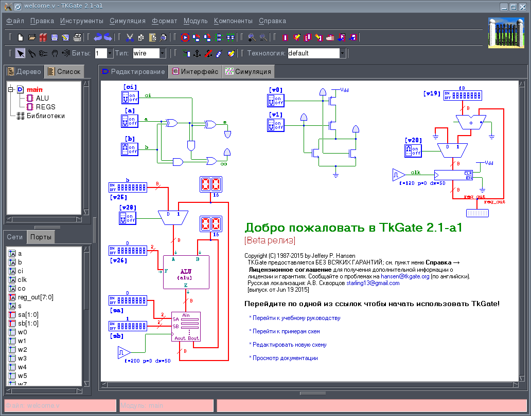
Under cat more detailed analysis of TKGate.
I used TKGate around 2005-2006, and I have the most positive memories of it. Then, around 2009, the development of the project stopped, and I did not have projects with digital electronics that needed to be modeled. Since that time, I have not seen this simulator and thought that the project has died. Now, fortunately, there was a developer who raised this project from the dead. Now let's take a closer look at this simulator. The key features of the simulator are as follows:
The schematic file is a regular Verilog script, the comments of which contain data on the location of components and wires. This Verilog code, for example, can then be transferred to CAD for FPGA synthesis.
The TKGate GUI is written in Tk / Tcl and therefore for those who are used to modern KDE and Gnome it looks a bit old-fashioned. Nevertheless, this does not harm the functionality of the program.
The simulator works only under Linux, the version for Windows can probably be compiled from the source code yourself.
The previous version of TKGate-1.8 is in the Debian repository, and to install it, just run the command:
There are no ready-made packages for the latest version, so you need to assemble it yourself. The following dependencies are required:
You can either download the source archive from the official website or clone the project repository on Bitbucket:
If you took the archive with the sources from the official site, then it should be unpacked in the directory where it was unpacked to execute:
If the repository is cloned, then the build sequence is more complicated:
You can replace make install with checkinstall, which will build the package for your distribution.
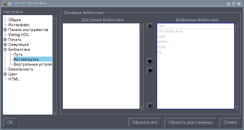
After installation, you need to configure the libraries loaded at program startup. You can download all libraries or some of them. To do this, click in the main menu Tools-> Settings and then in the dialog that appears, the Library-> Startup. Select the libraries loaded at startup. In particular, the program contains an IMS library of the 74th series (TTL and TTLSh). This completes the setup.
Libraries can be dynamically loaded by right-clicking on the Libraries item in the project tree in the left part of the program window and selecting the Library Manager item in the context menu.
Consider a small example. We model element 2I-NOT. To do this, create a new file: File-> Create.
An empty diagram opens. The central part of the main program window is the actual input field for the circuit.
Now you need to add the components. Components are added via the
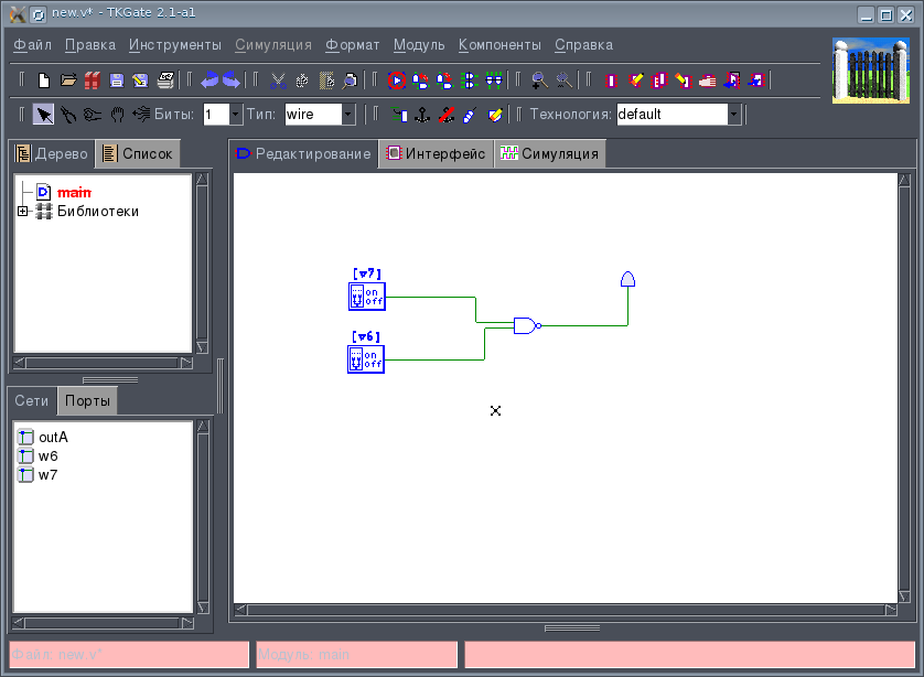
right-click menu on the schematic field. Select Components-> Valve-> NAND. The inputs of the valve must be connected to the switches, which will supply them with a log.0 or log.1, and an LED to the output in order to monitor the status of the valve 2AND. We select the switches again through the context menu Components-> Input / Output-> Switch. The LED is in the same place: Components-> Input / Output-> LED. Now we connect everything with wires. This should be a diagram like this:
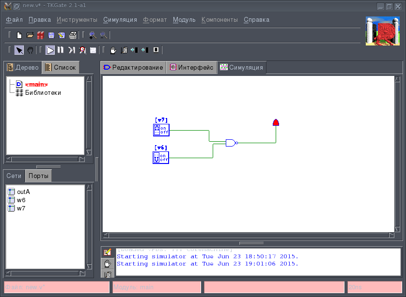
Now the circuit can be modeled. To do this, go to the Simulation tab. The Simulation menu becomes active. Now run the simulation: Simulation-> Start. Modeling is fully interactive, unlike, for example, modeling digital circuits in Qucs. The modeling approach in TKGate resembles Multisim or Proteus. During simulation, you can manually change the state of switches, etc. and watch the response of the circuit. In our scheme, if you click on the switches, we will see that the output state of the logic element changes depending on the state of the inputs according to the truth table of the 2AND-NOT element. To stop the simulation, you need to call the command Simulation-> End Simulation. The simulation result is shown in the figure:
More complex circuits may include mid-range integrated circuits, Verilog modules, RAM, and ROM.
Thus, we can conclude that, despite the break in development and the old-fashioned interface, TKGate is a fairly powerful tool for analyzing digital circuits.
- Official site of the tkgate.org project
- Bitbucket project repository: bitbucket.org/starling13/tkgate/branch/2.0
Under cat more detailed analysis of TKGate.
History and Key Features
I used TKGate around 2005-2006, and I have the most positive memories of it. Then, around 2009, the development of the project stopped, and I did not have projects with digital electronics that needed to be modeled. Since that time, I have not seen this simulator and thought that the project has died. Now, fortunately, there was a developer who raised this project from the dead. Now let's take a closer look at this simulator. The key features of the simulator are as follows:
- Interactive digital circuit modeling
- Available types of components: logic elements, triggers, registers, counters, decoders, multiplexers, RAM, ROM, ALU, keys on the MOS transistor, input signal simulators, LEDs, seven-segment indicators, scales, clock generators.
- Using custom Verilog scripts.
The schematic file is a regular Verilog script, the comments of which contain data on the location of components and wires. This Verilog code, for example, can then be transferred to CAD for FPGA synthesis.
The TKGate GUI is written in Tk / Tcl and therefore for those who are used to modern KDE and Gnome it looks a bit old-fashioned. Nevertheless, this does not harm the functionality of the program.
Installation
The simulator works only under Linux, the version for Windows can probably be compiled from the source code yourself.
The previous version of TKGate-1.8 is in the Debian repository, and to install it, just run the command:
apt-get install tkgate
There are no ready-made packages for the latest version, so you need to assemble it yourself. The following dependencies are required:
- Tk / tcl
- Gcc
- Autotools
You can either download the source archive from the official website or clone the project repository on Bitbucket:
hg clone https://bitbucket.org/starling13/tkgate
If you took the archive with the sources from the official site, then it should be unpacked in the directory where it was unpacked to execute:
./configure
make
make install
If the repository is cloned, then the build sequence is more complicated:
./configure
aclocal
automake
make
make install
You can replace make install with checkinstall, which will build the package for your distribution.
Customization
After installation, you need to configure the libraries loaded at program startup. You can download all libraries or some of them. To do this, click in the main menu Tools-> Settings and then in the dialog that appears, the Library-> Startup. Select the libraries loaded at startup. In particular, the program contains an IMS library of the 74th series (TTL and TTLSh). This completes the setup.
Libraries can be dynamically loaded by right-clicking on the Libraries item in the project tree in the left part of the program window and selecting the Library Manager item in the context menu.
Work with the program
Consider a small example. We model element 2I-NOT. To do this, create a new file: File-> Create.
An empty diagram opens. The central part of the main program window is the actual input field for the circuit.
Now you need to add the components. Components are added via the
right-click menu on the schematic field. Select Components-> Valve-> NAND. The inputs of the valve must be connected to the switches, which will supply them with a log.0 or log.1, and an LED to the output in order to monitor the status of the valve 2AND. We select the switches again through the context menu Components-> Input / Output-> Switch. The LED is in the same place: Components-> Input / Output-> LED. Now we connect everything with wires. This should be a diagram like this:
Now the circuit can be modeled. To do this, go to the Simulation tab. The Simulation menu becomes active. Now run the simulation: Simulation-> Start. Modeling is fully interactive, unlike, for example, modeling digital circuits in Qucs. The modeling approach in TKGate resembles Multisim or Proteus. During simulation, you can manually change the state of switches, etc. and watch the response of the circuit. In our scheme, if you click on the switches, we will see that the output state of the logic element changes depending on the state of the inputs according to the truth table of the 2AND-NOT element. To stop the simulation, you need to call the command Simulation-> End Simulation. The simulation result is shown in the figure:
More complex circuits may include mid-range integrated circuits, Verilog modules, RAM, and ROM.
Thus, we can conclude that, despite the break in development and the old-fashioned interface, TKGate is a fairly powerful tool for analyzing digital circuits.