LabView in robotics - creating a SCADA system for controlling a robot
Good afternoon, dear Habravites!
What is LabView and what does it eat with?
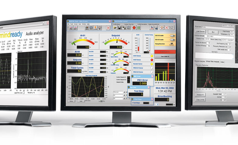
LabView is a cross-platform graphical development environment by National Instruments. LabView is widely used in data acquisition systems, as well as for the management of technical objects and technological processes.
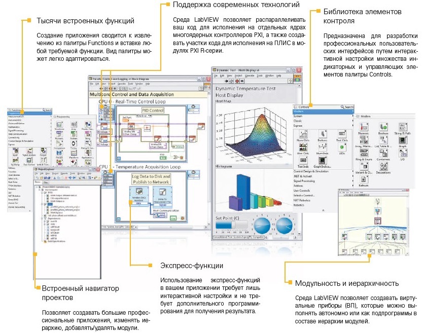
A distinctive feature of LabView is the "sharpened" environment for development under the "iron". A large number of libraries designed to interact with equipment from various manufacturers, allows you to quickly and comfortably prototype solutions to various problems, including for controlling robots and machine vision systems. In addition to the official LabVIEW Robotics Module, offered by National Instruments, and containing libraries for interacting with various robotic components, enthusiasts themselves develop a large number of libraries and, most importantly, distribute them for free. Today, you can see a large number of solutions in robotics using LabView - one of the most striking in recent years in our country - the Autonomous robot of the NAMT team at Robocross 2013 and Eurathlon 2013.
How it all began.
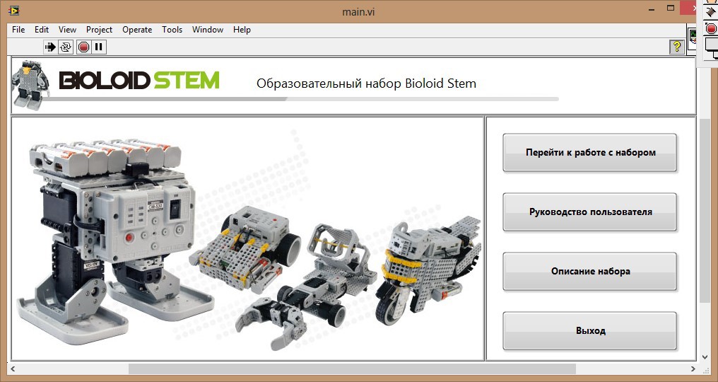
I am a graduate of MSTU. N.E.Bauman and am fond of robotics, although the main focus of my activity is industrial automation. Having met LabView a few years ago, I fell in love with this environment, and since then I have been trying to use it wherever possible. Currently, in addition to using LabView in various projects, I am conducting optional classes and laboratory work for students related to the use of LabView in data collection systems. Recently, thanks to our robot center, I managed to get robotic kits for using them for various scientific purposes. In this regard, I would like to publish a series of works related to the use of LabView in robotics, and the main emphasis will be on the implementation of the simplest examples, for further use in laboratory work for students. Not so long ago, I was asked to deal with a robotic designer from the Korean company Robotis and develop some simple examples on LabView to interact with this designer. Of particular interest was the fact that data exchange had to be arranged through the Zigbee wireless interface. As prototypes, the OLLO BUG and Bioloid STEM kits came to me.
Composition of the OLLO BUG
Bioloid STEM Kit Composition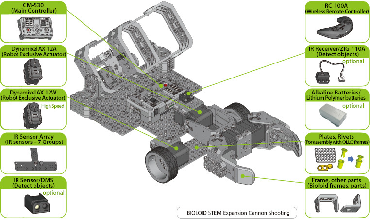
A distinctive feature of OLLO are more "simple" components in comparison with Bioloid. In particular, the OLLO kit includes the CM-100 controller, while the CM-530 is supplied with the Bioloid kit.
SM-100
SM-530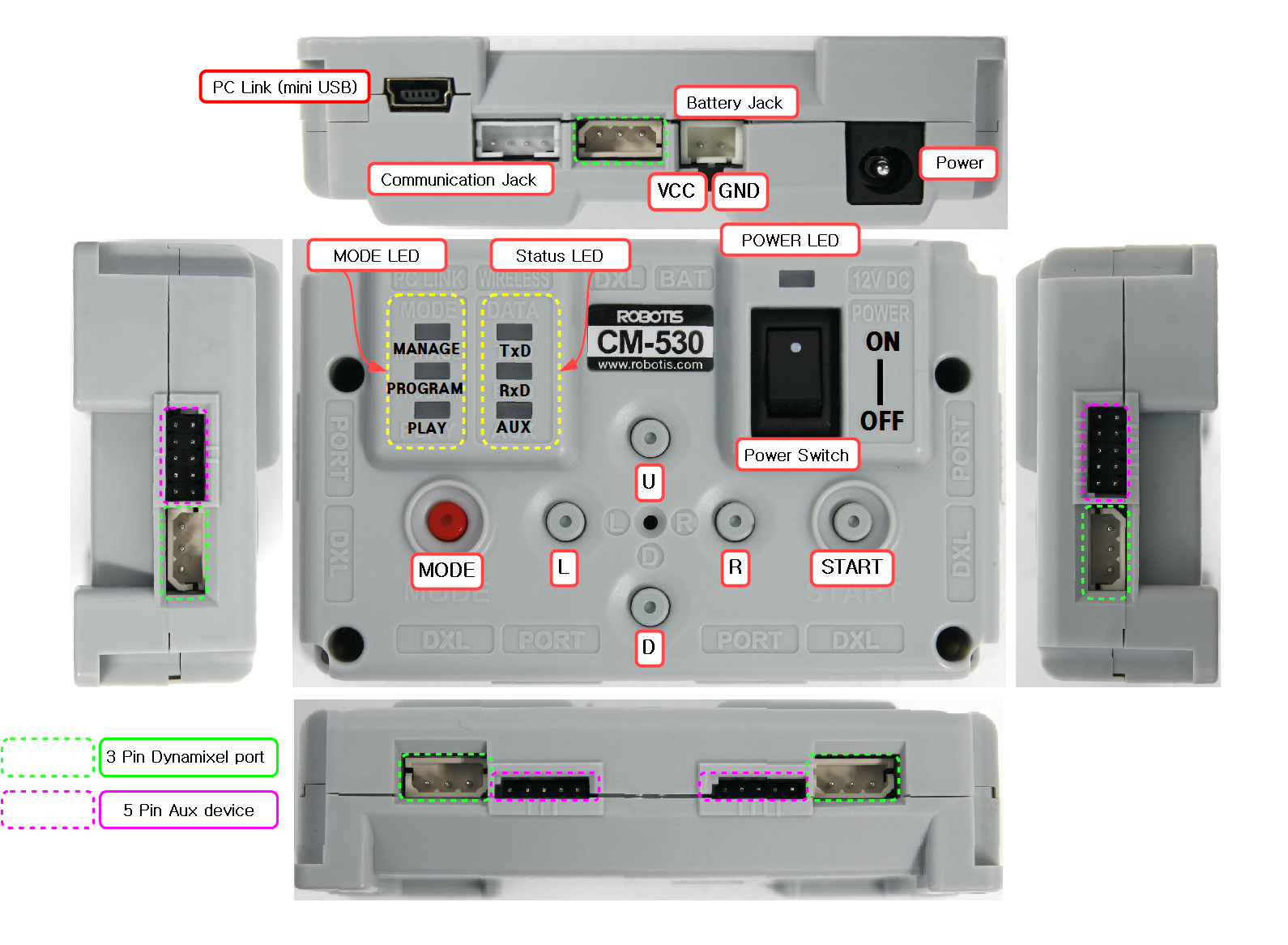
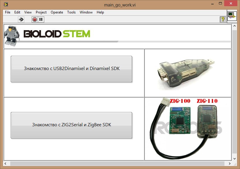
To organize the wireless interface, a bunch of “native” adapters supplied by Robotis was used:
1. ZIG-100 / 110A - connects to the controller (the one with the tail) and installs on the adapter (which is made in the form of a chip).
ZIG-100 / 110A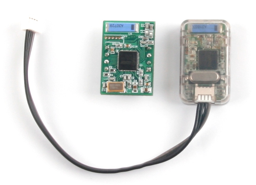
2. ZIG2Serial - a scarf, which is essentially an adapter from the zigbee module to the standard rs-232.
Zig2serial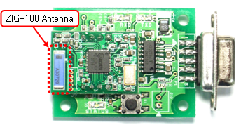
3. USB2Dynamixel is a very interesting and useful thing. It can work in 3 modes - TTL, RS485, RS232 - our option. We use this adapter as an adapter from USB to RS232.
USB2Dynamixel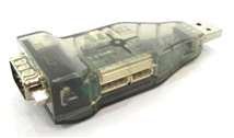
The result was such a design:
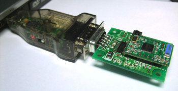
The only thing left to do is to establish a connection between the two “halves” of the ZIG-100 / 110A and proceed to actually
In order for our controllers to understand that the ZigBee module is connected to them and to exchange data between it and the peripherals connected to them, it was necessary to write the appropriate firmware for them. The firmware was written using the native RoboPlus Task. The process of writing the firmware is as follows:
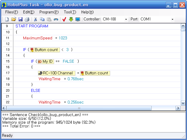
Since it is impossible to extract the firmware code from the RoboPlus Task in a form that is pleasing to the eye and compact, I will not upload the screenshots of the firmware in the future. Moreover, the development process itself is quite intuitive and does not cause any special problems. If someone is interested in the firmware itself - I will add them in .tsk format.
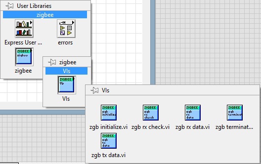
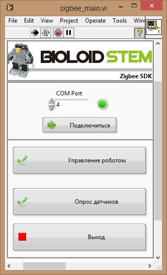
Initially, it was assumed that I would have to develop the library myself to work with ZIG2Serial, but rummaging around, on the official Robotis website I found the Zigbee SDK, which seamlessly integrated into LabView via the classic Import Shared Library (.dll). I conducted this process on LV2010 and LV2012 - no integration problems were found. As a result, we have another palette in User Libraries:
To demonstrate the capabilities of LabView, it was decided to implement the following as training examples:
1. Sending control commands to the controller through the Zigbee interface.
2. Poll array of infrared sensors connected to the controller.
3. Poll infrared sensors.
4. Interaction with Dynamixel servos.
So, let's start in order:
1. Sending control commands to the controller through the Zigbee interface.
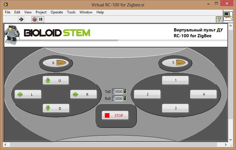
By control commands in this example, I mean commands that the controller perceives as commands sent from the RC-100 control panel, but nothing prevents us from sending any others - just in this case we would have to modify the firmware additionally.
RC-100 remote control diagram and codes corresponding to each button
The principle of operation in this case is as follows - it is connected via the com-port to the adapter, and we transfer data to the controller. The controller interprets them and sends the appropriate commands to the servos of the robot.
Vi development process
We implement this program in several stages.
1. Create a new block diagram. Place 2 Case Structures, a Round LED indicator with the name ZGB_Connected, and a Square LED indicator with the name TxD_LED. Create an OK Button named ZGB_Connect and connect it to the Case Selector input of the first structure. Set the behavior of this Mechanical Action button to Switch Until Released. Place the Flat Sequence structure with three windows (Frame) inside this structure in the True window.
2. Place the zgb_terminate.vi function from the Zigbee library inside the first window. This must be done to close the session with the COM port, in the case when the previous session was not correctly completed. Also in this window we place the local variable ZGB_Connected and assign it the value FALSE.
3. In the next window we place the function zgb_initialize.vi whose input we connect to the numeric control of the COM Port, and the output, comparing with the value “0”, is sent to the input Enable express-vi Display Msg. In the Message to Display window, write Initialization Failed. In this window, the connection with the COM port to which the ZIG-100 module is connected using ZIG2Serial and USB2Dinamixel will be initialized. If the connection is successfully initialized, the zgb_initialize.vi function will return the value 1, and if the connection is not successful, the value 0 will return a message about the failed initialization.
4. In the last window, place the Case Structure, connecting the input of which with the output of OK express-vi Display Msg. We put the False constant in the True window, and the True constant in the False window and connect them to the ZGB_Connected indicator.
5. Create an OK Button named Transmit. Set the behavior of this Mechanical Action button to Switch Until Released, and now move on to the second of the two Case Structures created at the beginning. We pass the value of the variable ZGB_Connected to the input of the structure using a local variable. Inside the True window, place the While Loop loop. Inside the loop, place the Case Structure, whose input is connected to the Transmit button.
6. Inside the structure we place the function zgb_tx_data.vi, the input of which is connected to the numeric control data to transmit, and the output, comparing with the value "0", is sent to the input Enable express-vi Display Msg located outside the structure. In the Message to Display window, write Transmission Failed. Also inside the True window of the current Case Structure, set the local variable TxD_LED to true. This step is necessary for sending data via Zigbee interface
7. In the False window of the current Case Structure, we place another Case Structure, passing in the value of the local variable TxD_LED to it, and in its True window we put the function zgb_tx_data.vi, with the value "0". This is necessary to filter the re-sending of commands.
8. Create a While Loop loop and put our entire block diagram inside it. Create a Stop button and set its behavior to Switch When Released. Connect the Stop button and Loop Condition of the last created While Loop loop. Also inside the current While Loop loop we place the Case Structure structure in its True window and place the zgb_terminate.vi function. We connect the input of the structure to the Stop button.
9. Let's go back to the first While Loop cycle created. By combining the local variables stop and ZGB_Connect with the logical OR operation, we connect the result of the operation with the Loop Condition of this loop.
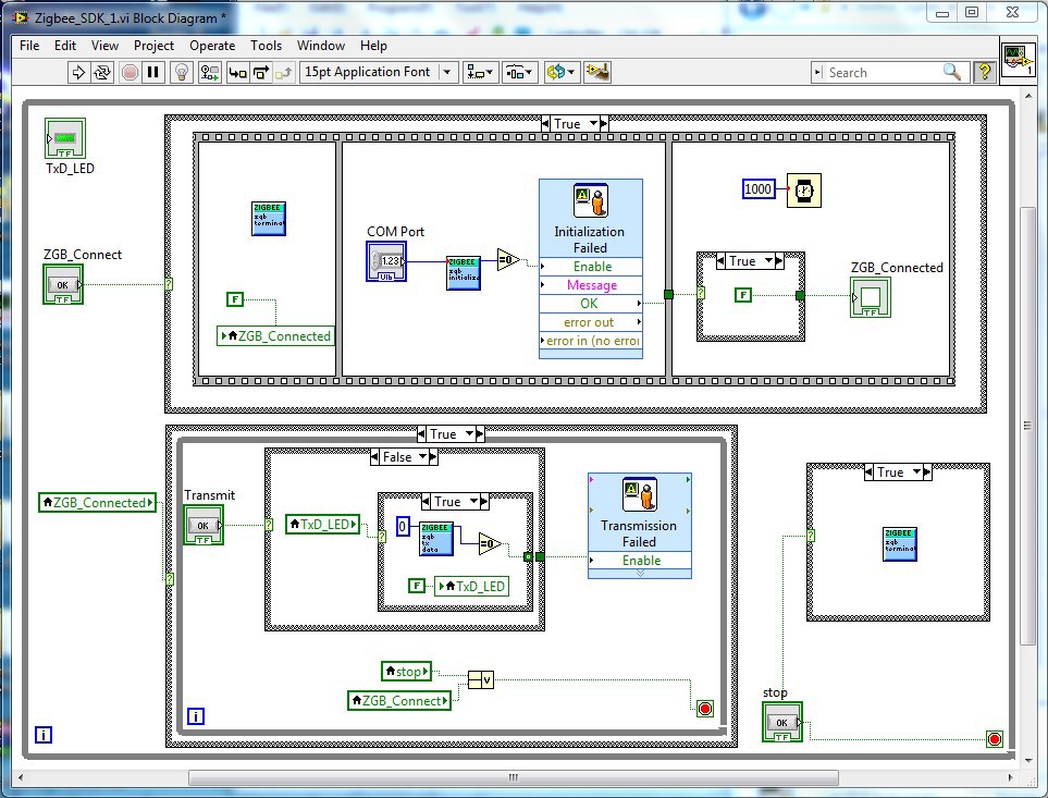
As a result, for this example, the block diagram is as follows:
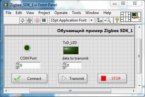
and the front panel:
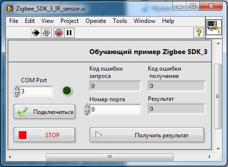
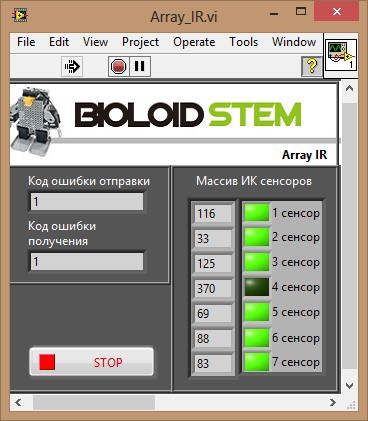
2. Poll array of infrared sensors connected to the controller.
An array of IR SENSOR ARRAY sensors can be connected to the CM-530 controller.
IR SENSOR ARRAY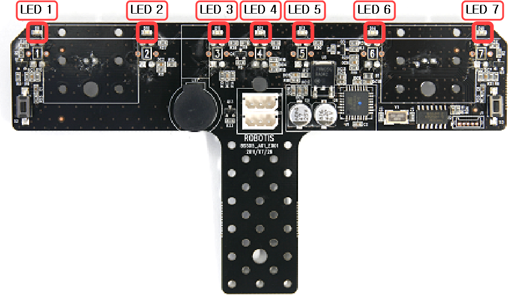
As an example, we will poll the sensor of interest to us on demand.
The principle of operation in this case is as follows - it connects via the com port to the adapter, we send to the controller the number of the sensor of interest to us - in response we get the value from it.
Vi development process
To complete this exercise, modify the previous vi in the following way:
1. Clear the first While Loop loop that we created from the contents.
2. Create a Case Structure and a control (control) with the name Request inside it. Connect this control to the input of Case Structure.
3. In the True window, place the Flat Sequence structure with three windows (Frame). Place the zgb_tx_data.vi function from the Zigbee library inside the first window. In this case, this function sends to the controller the number of the sensor of interest to us from the array. Therefore, we will create a control (control) with the name Sensor number and an indicator with the name Request error code and connect them, respectively, with the input and output of this function.
4. Inside the second window we place the function zgb_rx_data.vi. This function is responsible for receiving this computer via the Zigbee interface. Create an indicator with the name result and connect it to the output of the function, passing through the 3rd window of the Flat Sequence structure. In the third window we put the function zgb_rx_check.vi. This function is responsible for outputting the results. We also create the indicator Error code for receiving and connect it to the output of this function.
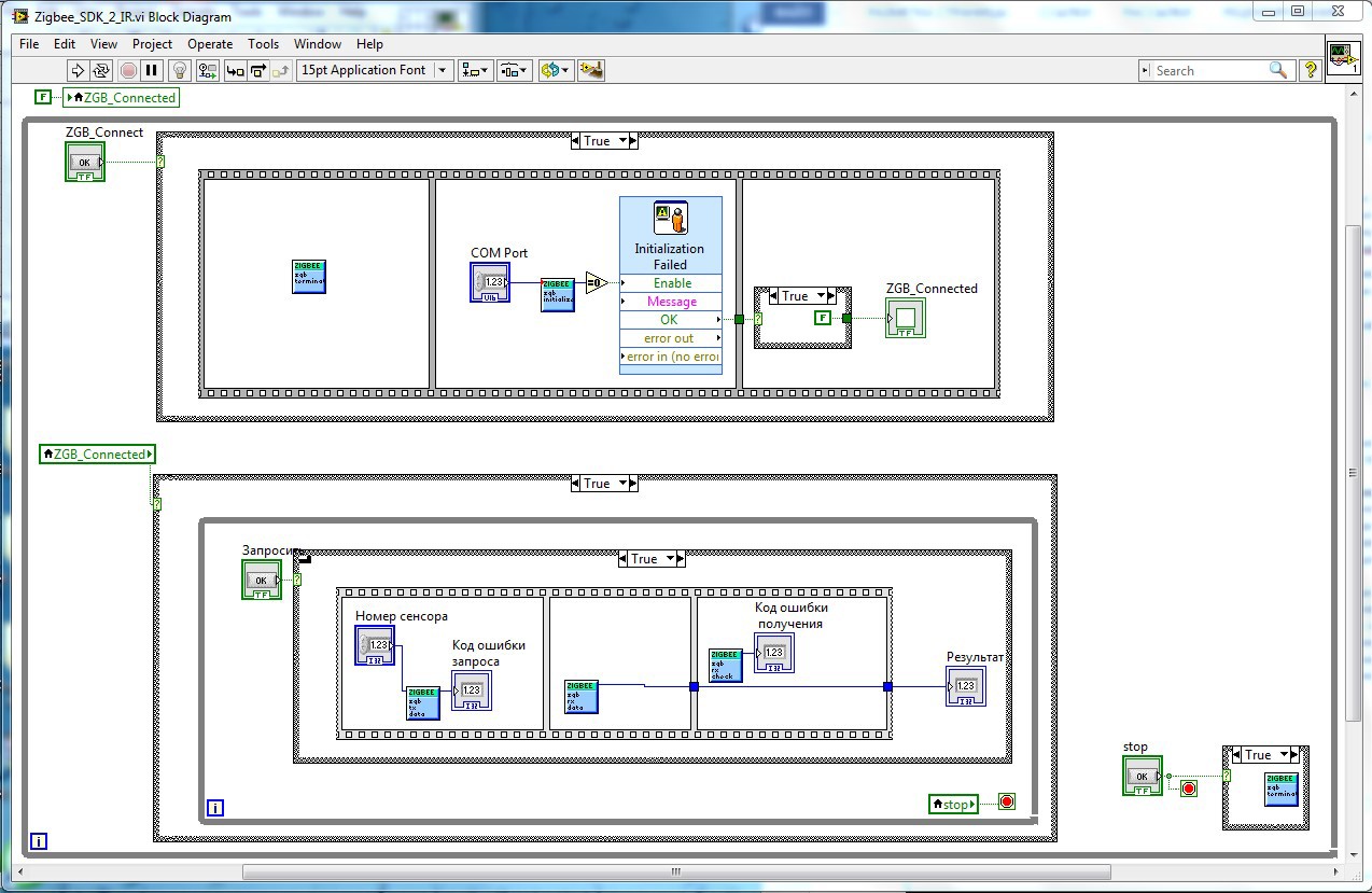
As a result, the block diagram is as follows:
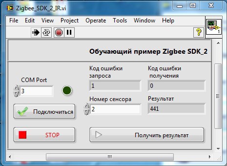
and the front panel:
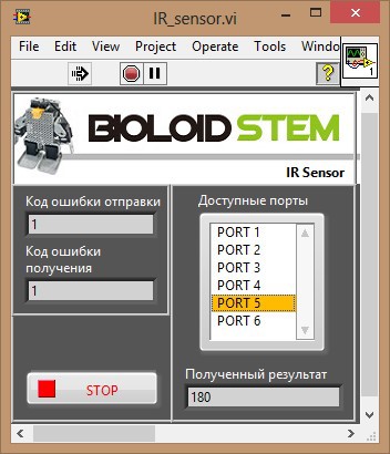
3. Poll infrared sensors.
In addition to the array of IR sensors, separate IR Sensor can be connected to the controllers.
IR Sensor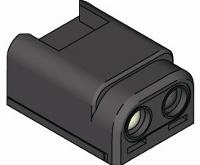
The implementation of this example does not differ significantly from the implementation of the previous one, so I will allow myself not to stop at the development process, I will just show what happened in the end.
The block diagram is as follows:
front panel:
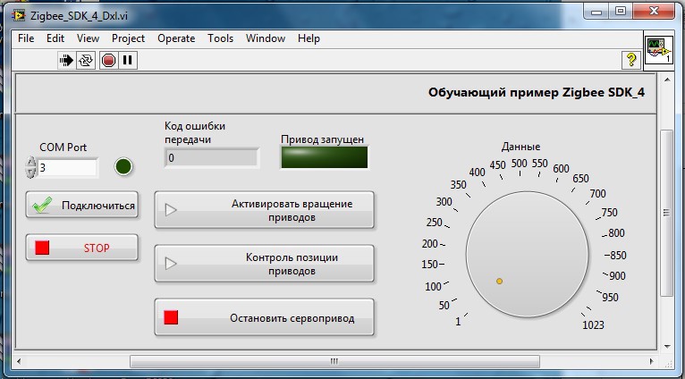
4. Interaction with Dynamixel servos.
The Bioloid STEM kit includes 2 Dynamixel AX-12A servos, and you can work with them in 2 modes - Joint and Wheel. In Wheel mode, the servo acts as a rotating motor, the main indicator is the speed of rotation. In Joint mode, the servo acts as a hinge, the main indicator of which is the deviation by a certain amount from its initial position. Operating modes are switched through RoboPlus Manager. A distinctive feature of this example is the continuous exchange with the controller via the Zigbee interface. To do this, parallel while loops were added to the block diagram. After selecting the operating mode (rotation of the drives or control of their deviation), the data are continuously sent to the controller, which are integer values from 1 to 1023.
The block diagram is as follows:

front panel:
As a result, these examples were included in the training courses on the basics of robotics offered by us.
Conclusion
Well, in conclusion, I want to say that the development of rather primitive examples did not end there. For a “quick” familiarization with the sets, a demo application was developed, which included “brought to mind” capabilities based on the above examples, as well as advanced capabilities for controlling and configuring servo drives in a “wired” mode of operation.
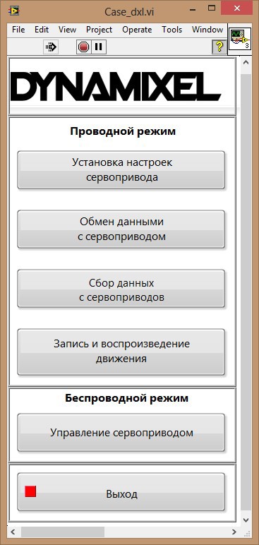
The main source of information during the development was www.robotis.com - the official website of the manufacturer.