We control the iRobot Roomba robot vacuum cleaner via IR
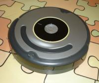
Before the new year I had a useful pet - iRobot Roomba 630. This is the most idle Roomba model without the scheduler functions. In general, I do not need these functions, I would rather control the robot from a PC, then it would be possible to run it remotely. To control the robot, iRobot manufactures an IR remote control, “Here it is!” - I thought and decided to try to make an IR transmitter to control the Roomb. All interested please ask for a cut!
How it works
Of course, the first thing I did was start looking on the Internet for the Roomb exchange protocol. There is not much information, but I found the most detailed description on the forum www.robotreviews.com , in particular, an interesting post , here is an abbreviated quote:
The remote control IR stream consisting of 8 bits each 4ms in duration. According to the paper, each bit is started by a 1ms low period. If the value is 0, the pulse stays low for 2 more ms. If the pulse goes high for 2ms if the value is 1. The bit is ended by sending a 1ms high burst.
The author also gives the codes of the teams he found.
Remote Button IR Stream Sensor Code
Left: 10000001 129
Forward: 10000010 130
Right: 10000011 131
Spot: 10000100 132
Max: 10000101 133
Clean: 10001000 136
Pause: 10001001 137
Power: 10001010 138
Forward / Left: 10001011 139
Forward / Right: 10001100 140
Docking station: Behind: 11110010 242
Docking station: Right: 11110110 246
Docking station: Slightly right: 11110111 247
Docking station: Left: 11111010 250
Docking station: Slightly left: 11111011 251
Docking station: Middle: 11111110 254
=== codes found by me ... not exactly sure ===
Docking station: Distant ???????? 248
Docking station: Distant ???????? 244
Docking station: Distant ???????? 240
Not sure ???? ???????? 252
At the indicated intervals, it didn’t work for me and I went the other way: on the same forum, the codes for irshell for managing with PSP were laid out .
Here they are
TITLE = Roomba
UP = Up
0000 0069 0000 0008 0070 0027 0023 0070 0023 0070 0023 0070 0023 0070 0023 0070 0070 0027 0023 030B
LEFT = Left
0000 0069 0000 0008 0070 0027 0023 0070 0023 0070 0023 0070 0023 0070 0023 0070 0023 0070 0070 02C8
RIGHT = Right
0000 0067 0000 0008 0072 0024 0024 0072 0024 0072 0024 0072 0024 0072 0024 0072 0072 0024 0072 02D0
CIRCLE = Spot
0000 0067 0000 0008 0074 0024 0024 0074 0024 0074 0024 0074 0024 0074 0074 0024 0024 0074 0024 0324
CROSS = Clean
0000 0069 0000 0008 0071 0027 0023 0071 0023 0071 0023 0071 0071 0027 0023 0071 0023 0071 0023 030B
TRIANGLE = Dock (MAX on older models?)
0000 0069 0000 0008 0070 0027 0024 0070 0024 0070 0024 0070 0024 0070 0070 0027 0024 0070 0070 02C8
L_SQUARE = Power off
0000 0069 0000 0008 0070 0027 0023 0070 0023 0070 0023 0070 0070 0027 0023 0070 0070 0027 0023 0023 030B
L_TRIANGLE = Pause
000069 0069 0000 0008 0070 0023 0023 0070 0023 0070 0023 0070 0070 0023 0023 0070 0023 0070 0070 02C8
Here the commands are written in codes in the hexadecimal system, this is the so-called Pronto IR format. I found a good description ( Yandex.Disk - just in case) their record turned out to be quite simple.
Some illustrations from the format description

Consider the Clean command as an example. it was most interesting to me:
0000 0069 0000 0008 0071 0027 0023 0071 0023 0071 0023 0071 0071 0027 0023 0071 0023 0071 0023 030B0000 - Tells us that it is a Pronto RAW format, illustrations of its recording are higher.
0069 - Carrier Frequency: 69 16 = 105 10 ; f = 4.145146 MHz / 105 = 39.477663 kHz.
0000 - So there is no starting non-repeating command.
0008 - The repeating command consists of 8 bits.
Next is a record of a repeating command, in the form of the number of periods of the carrier frequency.
0071 - The first pack lasting 71 16 periods, i.e. approximately 2862 μs.
0027 - We don’t transmit anything 27 16 periods, i.e. approximately 988 μs.
Further - by analogy. It turns out that the signal should look like this:

If the first pack is one, and the second is zero, then the command codes from the message from the forum are correct:
| Command | The code |
|---|---|
| Left | 129 |
| Forward | 130 |
| RIGHT | 131 |
| Spot | 132 |
| DOCK | 133 |
| Clean | 136 |
| PAUSE | 137 |
| Power | 138 |
| FORWARD_LEFT | 139 |
| FORWARD_RIGHT | 140 |
Manufacture
Of course, you could buy any IR transmitter with a USB connection and feed a special program to the above Pronto Raw codes and that's it! I did not like this idea, at first I wanted my IR transmitter to be used separately from a PC, i.e. it should be with buttons and a battery, but then decided to control the remote with buttons and leave it for later. I wanted the transmitter to be controlled via USB-UART and that it understood just text commands, then it could even be connected to a router.
The scheme is quite simple:

Components:
- FTDI FT232RL
- Atmel ATtiny2313-20SU in SOIC20 package
- Quartz at 7.3728 MHz
- 4 capacitors 0.1 microfarad SMD0805
- 2 capacitors at 20pF
- 1 x 10 uF tantalum capacitor
- 1 SMD LED (frame size 1206) to indicate FT232 operation (optional)
- 1 560 ohm SMD resistor for LED (again optional)
- 1 IR LED, I used L-34F3C
- 1 SMD resistor per 100 ohms for IR LED.
The signal to the IR diode is fed through 5 pins of the MK, of course, it would be more correct to control the transistor, but I wanted to make the circuit as simple as possible. When choosing a resistor R2, you need to remember that the maximum current for ATtiny2313 is 200 mA for all pins, and for 1 pin 40 mA.
The information LED is connected to the CBUS3 pin of the FT232 chip, by default, the PWREN # signal is output to it, i.e. The LED is on when the FT232 is connected to the PC and initialized. You can also assign another function to this output, for example, RXTXLED # - then the LED will blink when transmitting data. This can be done using the FT_PROG utility . There are no utilities for Linux that can change the pin assignment.
Because I use Ubuntu OS at home, I decided to distribute the board in KiCAD (this is certainly not Altium Designer, but it does its job), I used all the components from the standard libraries:

Archive with the KiCAD project: Remote_USB_PCB.zip The
board is single-sided, etched using the LUT method a.
It is worth noting that I specifically chose the controller in the SOIC package, because it is easier to place on the board and etching / soldering is also easier. But the distance between the legs of the FT232RL is quite small, so after transferring the toner to the board, before etching, you need to clean the distance between the terminals from the remnants of the paper with some sharp object. I was too lazy and did not do this, as a result I had to cut platforms in some places, otherwise they merged.
Due to my desire for simplicity, the board was originally without quartz, and it looked like this:

But apparently, the stability of the internal RC generator was not enough and Roomba did not react to commands, although the waveforms of several periods showed that everything was fine. As a result, I attached quartz to trim the unnecessary board from above:

Programming
The program is written in C (AVR-GCC), I wrote mainly in CodeBloks, but I had to debug it once in Atmel Studio. The code does not pretend to be “correct” and “beautiful”, incl. I ask you to take this into account and do not criticize much (but useful instructions are welcome).
Listing
/*
Управление роботом-пылесосом Irobot Roomba с ПК через USB-UART (FTDI FT232R). Программа для контроллера Atmel ATTINY2313.
FUSE-биты:
Fuse Low Byte:
CKDIV|CKOUT|SUT|SKSEL|
  0  |  1  |10 |0100 | 0x64 Default
  1  |  1  |10 |1100 | 0b11101100=0xEC  для кварца 7.3728 МГц
*/
#define F_CPU 8E6
//#define __AVR_ATtiny2313__
#include
//#include
//#include
//#include
//#include
//#include
//#include
/*------<Макросы>-----*/
//Частота 39477 Гц
//39500 Гц Переод 25,3 мкС
#define P_GEN {TCNT0=0; PORTB |= 0x1F; while (TCNT0 < 93); PORTB &= ~0x1F; while (TCNT0 < 186);}
#define TX_LFCR tx_uart(0x0A); tx_uart(0x0D);
//Roomba коды:
#define LEFT 			129
#define FORWARD 		130
#define RIGHT 			131
#define SPOT 			132
#define DOCK 			133
#define CLEAN 			136
#define PAUSE 			137
#define POWER 			138
#define FORWARD_LEFT  	139
#define FORWARD_RIGHT 	140
/*------< Глобальные переменные >------*/
volatile unsigned char data;
unsigned char status;
/*----------------<Функции:>----------------*/
void init(void)
{
//Установка делителя частоты на /1:
	//CLKPR = (1<> cnt))
            {	//Если 1
                while (TCNT1 < 330) P_GEN;
                while (TCNT1 < (330+114)) ;
            }
            else
            {	//Если 0
                while (TCNT1 < 113) P_GEN;
                while (TCNT1 < (330+114)) ;
            }
        }
        TCNT1=0;
        while (TCNT1 < 1950)  ;
    }
}
void tx_uart(unsigned char tx_data)
{
	UDR = tx_data;
	while (!(UCSRA & (1<-----------------------*/
int main(void)
{
	init();
	for(;;)
	{
		while (!(UCSRA & (1<': ir_tx(FORWARD_RIGHT); TX_LFCR break;
			default: tx_help();  TX_LFCR break;
		}
	}
}
Archive with the project: Roomba_Remote_USB.zip | Separately, the hex file was
flashed by the USBasp programmer using the avrdude utility.
For flashing Fuse-bits you need to run with the parameters:
avrdude -p t2313 -c usbasp -U lfuse:w:0xEC:m
To flash the hex file:
avrdude -p t2313 -c usbasp -U flash:w:./bin/Debug/Roomba_Remote.elf.hex
To send a command, you need to type the appropriate character in the terminal:
| Command | Symbol |
|---|---|
| Left | L |
| Forward | F |
| RIGHT | R |
| Spot | S |
| DOCK | D |
| Clean | C |
| PAUSE | P |
| Power | W |
| FORWARD_LEFT | < |
| FORWARD_RIGHT | > |
There is another undocumented function - see listing. ;-)
The controller responds to the correct command with a line feed, to the wrong one with brief help.
A small video with a demonstration of work:
Now I am not satisfied with the working range: you need to direct the LED exactly at Roomb, and this is not very convenient. In this connection, I am thinking of replacing the R2 resistor with a resistor with a lower nominal value, for example 68 Ohms, or changing the IR LED.
I’m also thinking about a conventional remote with buttons, in connection with which there is a poll below.
PS
Please inform about spelling errors and design errors via LAN.
Only registered users can participate in the survey. Please come in.
When I assemble a simple remote with buttons, do I need to write an article about it?
- 81.5% needed, it will be interesting to read. 283
- 6.6% is needed, even though I have an iRobot factory remote control. 23
- 6.3% No need, I already have an iRobot factory remote control. 22
- 13.5% No need - so everything is clear! A little fix the program and that's it. And in general, I have already assembled it. 47