Determination of resistance by a controller without ADC
Actually, there was such a task - to read the potentiometer readings several times per second. The target information receiver is the ATmega32 controller. It has a built-in ADC, but the result issued by it had a resolution of 2-3 bits, and the remaining bits carried garbage.
The first thing that came to mind was to buy an external ADC and screw it to the controller. But there was neither the time nor the desire to deal with another device. I decided to try another method, whose performance I was not sure about, but nevertheless the circuit turned out to be quite working and gave an accuracy of the order of 8 bits (maybe more, did not check).
Actually, the idea is that the digital input of the controller measures the discharge rate of the capacitor. The capacitor is charged to the supply voltage through a low resistance, then a time report is started, and the capacitor is discharged through the potentiometer. When the voltage on the capacitor drops to 1.4V (voltage switching the controller input to low), the value of the logic level at the input will switch and the time report will stop. The resulting discharge time is proportional to the current resistance of the potentiometer.

A0, A1 - MK legs, digital port A. The
transistor in the circuit is used so that the voltage to which the capacitor is charged does not depend on the current position of the potentiometer.
To ensure good measurement accuracy, it is necessary to select the elements of the circuit in such a way that the discharge time at the extreme positions of the potentiometer differs by approximately an order of magnitude. In general, the more the better, but there’s a chapel for everything.
The formula for the discharge time of a capacitor through a resistor (from a wiki):

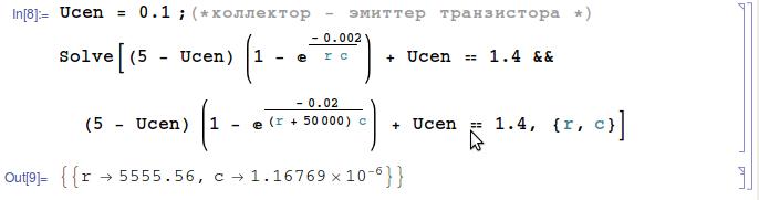
It is necessary to select R and C in such a way as to ensure the discharge time from 5V (VU) to 1.4V (the level of switching the port to logical 0) for a time of 0.02 seconds at maximum resistance, and for a time of 0.002 seconds at minimum resistance. In this case, the value of C is constant in both cases, and R differs by 50 kOhm (potentiometer value). The time was chosen for reasons of accuracy, the speed of the microcontroller, and was selected to most closely match the available values of resistors and capacitors. (the controller operates at a frequency of 8 MHz)
Solving the system of equations, we determine the value of resistor R13 and capacitor C1.
Here, the internal resistance of the controller input is not taken into account, but the speed of the controller made it possible to programmatically configure the circuit and select a coefficient for transferring the discharge time to the range 0..255.
R12 is used to charge the capacitor and should be small, R14 should provide the saturation mode of the transistor at any possible current.
R12 = 220 ohms;
R13 = 6.8 kΩ;
R14 = 1 kΩ;
R 15 = 0..50 kΩ;
C1 = 1 uF.
To charge the capacitor, the transistor is turned off, and the leg A0 is set to a high level output (DDRA = 3, PORTA = 1). and a delay is made for a sufficiently longer time for charging the capacitor. Then A0 switches to the input state, and the transistor opens (DDRA = 2, PORTA = 2). the capacitor starts to discharge, the discharge time is monitored by an empty cycle.
Below is the actual code of the function involved in measuring the discharge rate.
The circuit works well, 8-bit removable are stable. You can probably speed up the circuit by recounting the parameters for less time, but the limitations on this are the input parasitic input capacitance and controller operating time.
I did not check, but I think that it is possible to reduce the discharge time by 10-20 times, and this will not affect the accuracy of the result.
The first thing that came to mind was to buy an external ADC and screw it to the controller. But there was neither the time nor the desire to deal with another device. I decided to try another method, whose performance I was not sure about, but nevertheless the circuit turned out to be quite working and gave an accuracy of the order of 8 bits (maybe more, did not check).
Actually, the idea is that the digital input of the controller measures the discharge rate of the capacitor. The capacitor is charged to the supply voltage through a low resistance, then a time report is started, and the capacitor is discharged through the potentiometer. When the voltage on the capacitor drops to 1.4V (voltage switching the controller input to low), the value of the logic level at the input will switch and the time report will stop. The resulting discharge time is proportional to the current resistance of the potentiometer.
Device Diagram:
A0, A1 - MK legs, digital port A. The
transistor in the circuit is used so that the voltage to which the capacitor is charged does not depend on the current position of the potentiometer.
Calculation scheme.
To ensure good measurement accuracy, it is necessary to select the elements of the circuit in such a way that the discharge time at the extreme positions of the potentiometer differs by approximately an order of magnitude. In general, the more the better, but there’s a chapel for everything.
The formula for the discharge time of a capacitor through a resistor (from a wiki):
It is necessary to select R and C in such a way as to ensure the discharge time from 5V (VU) to 1.4V (the level of switching the port to logical 0) for a time of 0.02 seconds at maximum resistance, and for a time of 0.002 seconds at minimum resistance. In this case, the value of C is constant in both cases, and R differs by 50 kOhm (potentiometer value). The time was chosen for reasons of accuracy, the speed of the microcontroller, and was selected to most closely match the available values of resistors and capacitors. (the controller operates at a frequency of 8 MHz)
Solving the system of equations, we determine the value of resistor R13 and capacitor C1.
Here, the internal resistance of the controller input is not taken into account, but the speed of the controller made it possible to programmatically configure the circuit and select a coefficient for transferring the discharge time to the range 0..255.
R12 is used to charge the capacitor and should be small, R14 should provide the saturation mode of the transistor at any possible current.
The final choice of values of the elements of the circuit:
R12 = 220 ohms;
R13 = 6.8 kΩ;
R14 = 1 kΩ;
R 15 = 0..50 kΩ;
C1 = 1 uF.
To charge the capacitor, the transistor is turned off, and the leg A0 is set to a high level output (DDRA = 3, PORTA = 1). and a delay is made for a sufficiently longer time for charging the capacitor. Then A0 switches to the input state, and the transistor opens (DDRA = 2, PORTA = 2). the capacitor starts to discharge, the discharge time is monitored by an empty cycle.
Below is the actual code of the function involved in measuring the discharge rate.
uint8_t readADC()
{ 	// контенсатор уже заряжен
	DDRA = 2;
	PORTA = 2;
	int i = 0, t = 0;
	while (PINA & 1){
		t++;
		if (t == 43) i++, t = 0; // константа 43 подобрана экспериментально
	}
	PORTA = 1; // что бы конденсатор опять заряжался
	DDRA = 3;
//если необходимо оцифровывать беспрерывно,
//нужно сделать небольшую задержку, что бы конденсатор
//успел зарядится до высокого уровня напряжения
	i -= 40; // подобрано экспериментально
	if (i < 0) i = 0; // вдруг появятся помехи и значения будут неожиданные
	if (i > 255) i = 255;
	return i;
}
The circuit works well, 8-bit removable are stable. You can probably speed up the circuit by recounting the parameters for less time, but the limitations on this are the input parasitic input capacitance and controller operating time.
I did not check, but I think that it is possible to reduce the discharge time by 10-20 times, and this will not affect the accuracy of the result.