Wiren Board 5: flexibility and modularity
Hello!
Recently we wrote about ( once and twice ) that we released a new version of the controller for automation - Wiren Board 5. Today we will tell in detail, perhaps, about the most important thing in the controller - its expansion modules.
Why it is needed.
Our first idea was to make a sufficiently versatile controller for home and commercial automation - with different wired and wireless interfaces, RS-485, inputs for connecting buttons, relays, etc. The advantage of this approach is a very high functionality / price ratio: for little money the user gets a bunch of interfaces.
The experience of using the first versions of controllers showed that only a few interfaces are usually used.
And if wired interfaces are used, they quickly begin to be missed: for example, if the meters and peripheral devices are connected via RS-485 and have different protocols, then often they are not compatible and they need to be connected to different ports. If buttons, counters and sensors with “dry contact” outputs are connected, there are a lot of corresponding inputs needed and they are not enough, etc.
Often customers ask for some very specific functions. Of course, you can “redraw” the controller to implement the necessary functionality, but the launch of a new revision of equipment, even with minor changes, is a big deal, working for 2-3 months:
- Four-layer board - long production time, as a prototype, and a series.
- Manually boards of such complexity are poorly soldered - the series must be given to automatic installation, and not to manual.
- For each new version of the board, a new hardware and software is required for testing.
Because of this, I would very much like to have a controller in the form:
- Basic controller, with basic functionality and a large reserve for expansion
- A series of simple expansion cards, “brainless”, with convenient connectivity.
This scheme has the following advantages:
- Specific functions are easy to add to the controller. Expansion boards are easily made for the customer. They are double-layered, easy to design and convenient for manual soldering.
- New revisions (bug fixes, improved design) for the controller and expansion cards are made separately. Accelerated development and launch on sale.
As a result of much thought, the modular design of the WB5 was born.
The first type of modules is soldered to the microassembly controller board.
- GSM (when installing on an automatic line, we do not install a module on a part of controllers). It is inconvenient, but no other method was invented.
- Wi-Fi and 433MHz radio. Small scarves, soldered on their own capacities before assembling a batch for a customer.
About other types we will tell more.
Mezzanine Modules
These modules are installed on the DIN-rail on the second floor:
- Battery module. With his development had pretty tricky. Everything is complicated there, but not interesting.
- Second Ethernet (coming soon)
- Display (in plans)
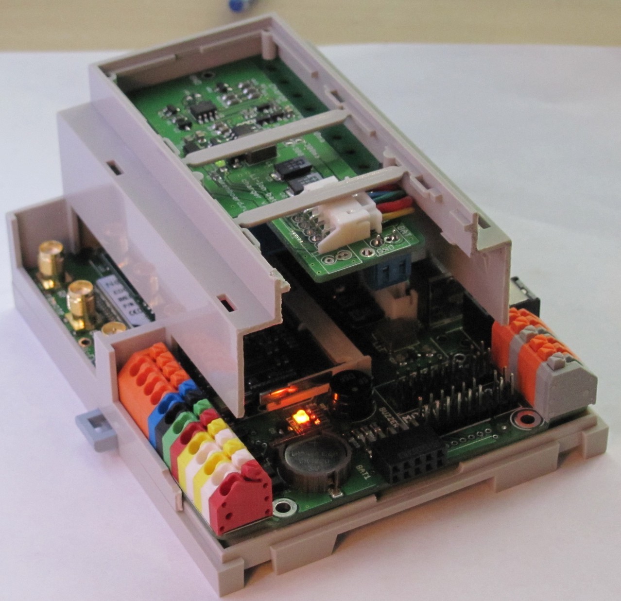
Expansion modules.
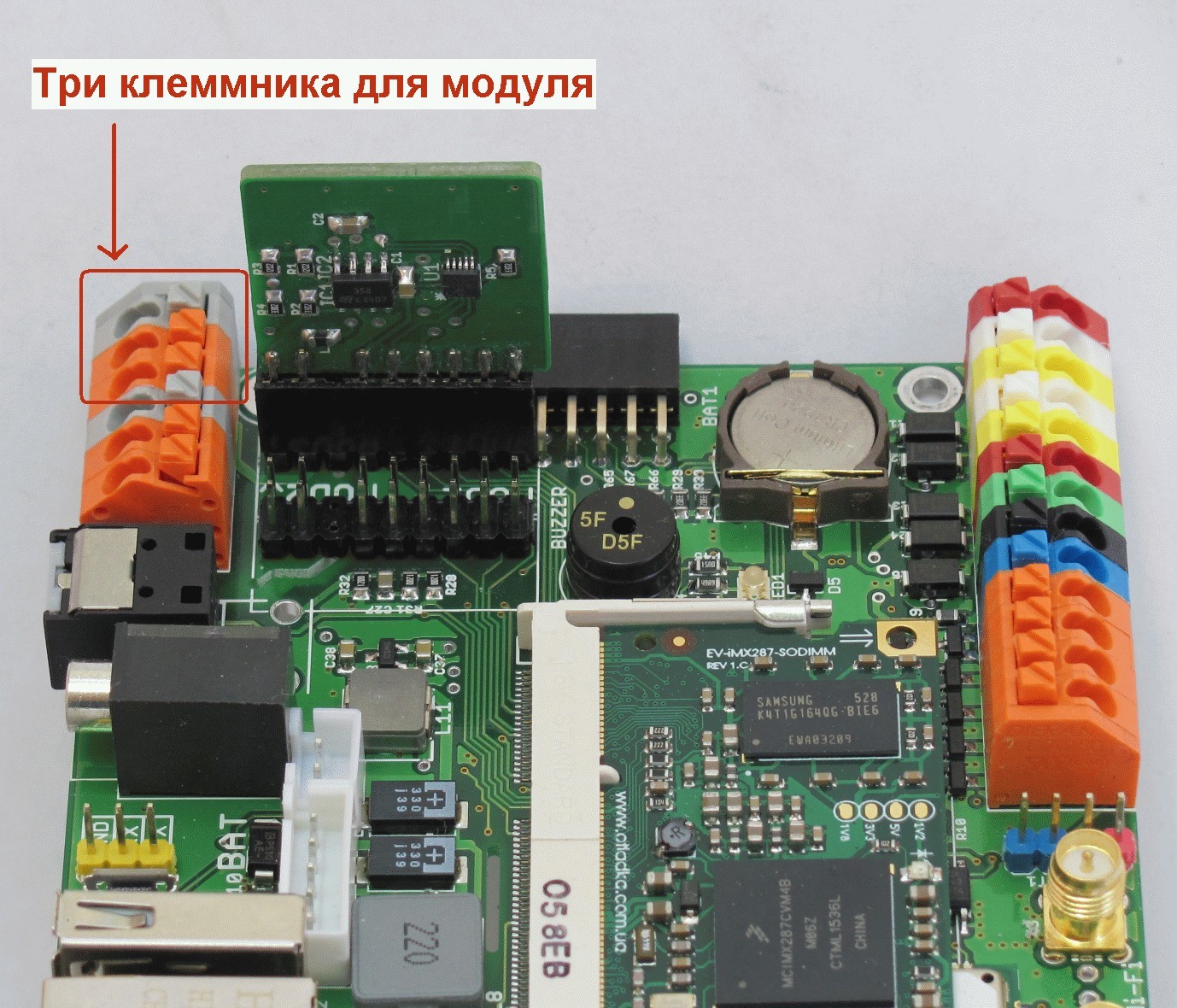
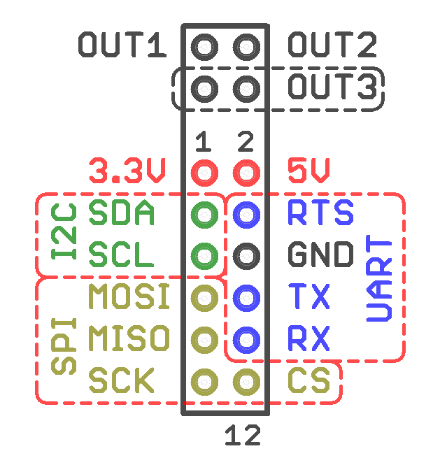
These are small scarves, placed vertically in the controller. In the Wiren Board 5 controller there are two slots for them, for each slot there are three terminals. Power, interfaces UART, SPI, I2C, GPIO are brought to the combs. When assembling, the boards are pressed against the case from above, so they cannot fall out of vibration.
Already developed:
-RS-232.
-CAN (insulated)
-RS-485 (isolated)
-ATSP - (soon to be) voltage inputs, the inputs 0-20mA, PT100 and PT1000 sensors
-TSAP - outputs 0-10V
-3 input "dry contact"
-GPS / Glonass
- Additional 1-Wire
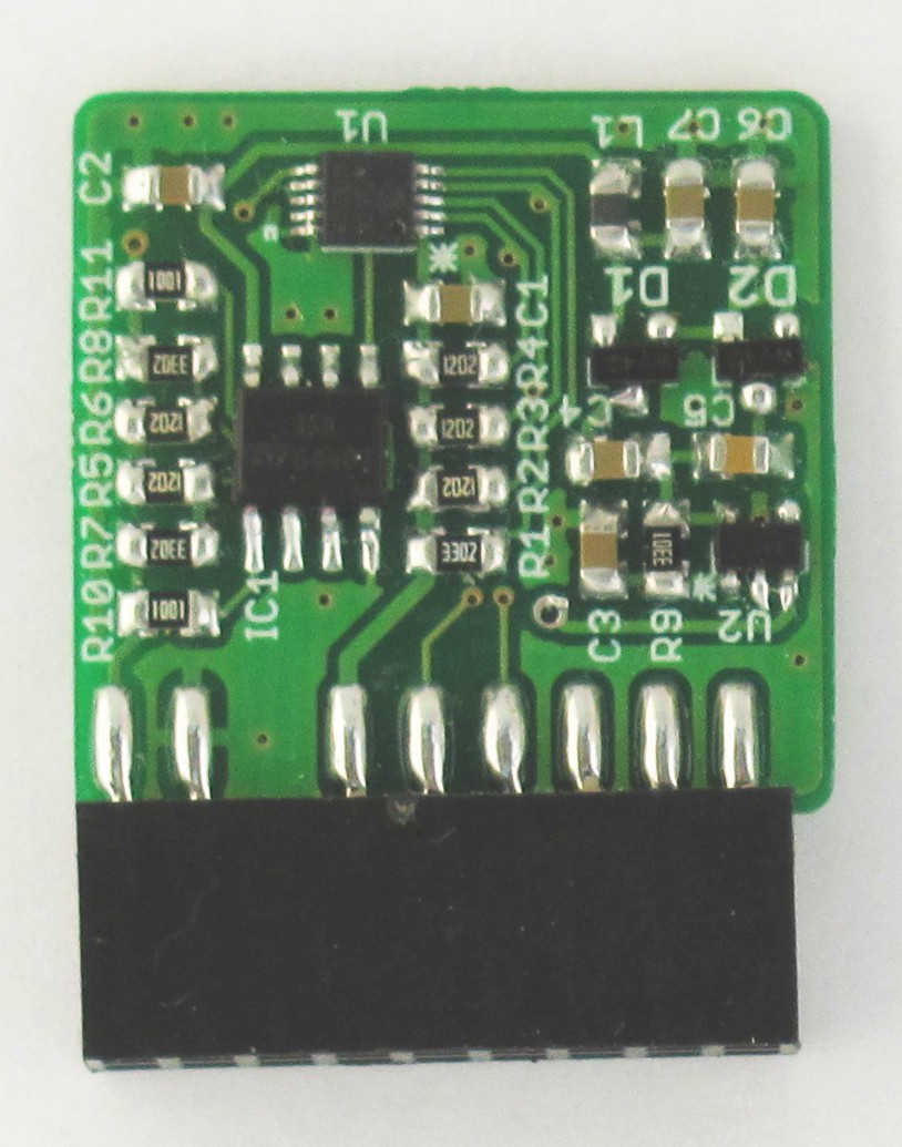
-microSD card
-Relay SPDT 6A
Mostly they are simple, there is really nothing to tell about the circuitry, so we go ahead.
I / O modules.
But about this type is to tell more.
Often there are tasks when you need a large number of I / O channels - connecting pulse meters, controlling contactors, etc. In this case, we connect external, side modules, which are joined to the controller in series up to 8 pieces.
An I / O module needs additional GPIOs. The easiest way to do this is using the so-called GPIO extenders for I2C. We use extenders MCP23008 and MCP23016. They have three legs for setting the address, so it is possible to have up to 8 devices on the bus. Addresses are distributed as follows - 000 100 010 001 - sequentially by module.
Addresses are inverted on the input modules, and they get the addresses 111 011 101 110. This allows you to connect up to 8 pieces (4 + 4) and in the future automatically determine their type - input it or output.
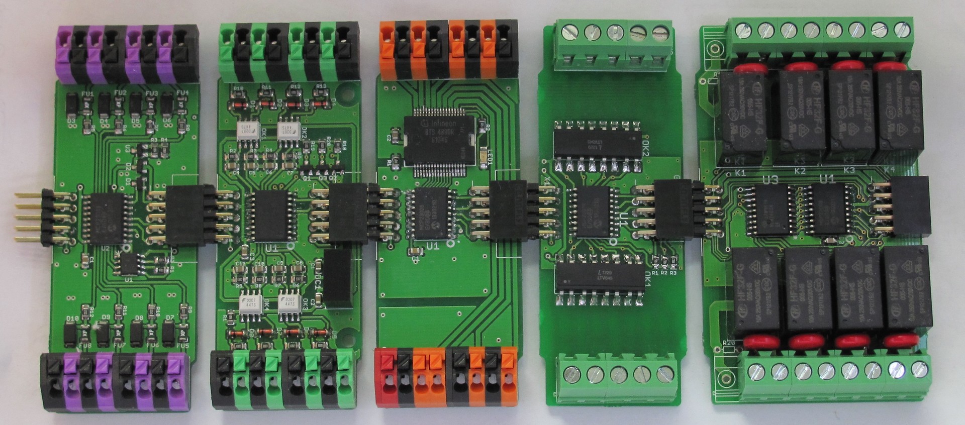
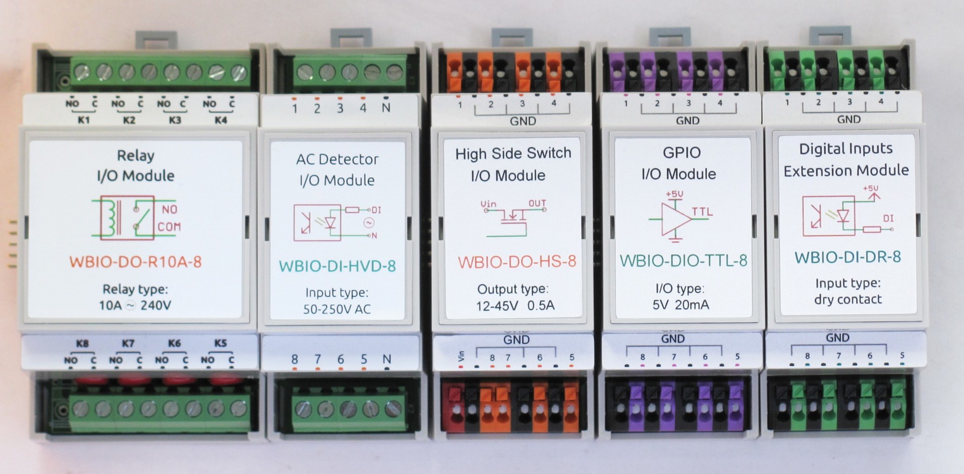
From left to right are the modules: TTL I / O, “dry contacts”, “High side switch”, “Inputs 220V”, relay block.
More about each:
Relay unit.
8 Relays for 10A @ 230V, with protection against arcing of contacts on varistors.
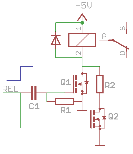
To reduce consumption and heat, after turning on the relay, you can reduce the current on the control coil by 2 times. The simplest way is to use the circuit as in Figure 1 - Turn on the relay with two transistors, one with a resistor. We give a signal - both transistors open - the nominal current flows, through time R1C1 the transistor Q1 closes - the current flows through R2. By reducing the current by 2 times, we reduce consumption by 2 times.
A more reasonable way to control a relay is to use PWM. Then, reducing the current by 2 times, reduce the consumption by 4 times. It is good when there is a microcontroller: it has many shima channels, you can control it directly with a transistor. But what if SHIMA is not? Need to do it. Take the 555th timer, or rather its reincarnation MIC1557, and let it generate PWM for us with a duty cycle of 50%. On the diodes collect the logical element “OR”. So when you turn on any of the relays, the timer is turned off and the relay receives a full 5V.

Module “Inputs 220V”
Module to determine the presence of voltage in the network. 8 channels.
The simplest solution for monitoring 220 V is an optocoupler with a resistor. The problem with such a simple solution is that the optocouplers have a large CTR (current transfer ratio) and reliable operation requires at least 1 mA of current, and the input must be from 50V AC - as a result, a lot of heat is generated on the resistor. And since inputs 8 - then the board will be very hot.
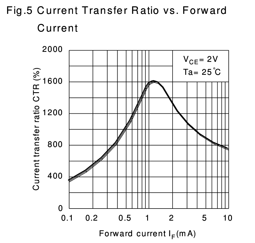
There are different ways to reduce heat. For example, you can use an optocoupler with a transistor Darlington output (large CTR), and use a capacitor instead of a resistor. We didn’t put the capacitor, but used the following trick: if you look at the “CTR vs. input current” characteristic of the optocouplers, you can see that the curve has a peak at a current of 1-2 ma. Therefore, if current is supplied with short pulses of 1 ma each, it is possible to ensure a high CTR with a low average input current. The dinistor and the capacitor form these pulses to us.
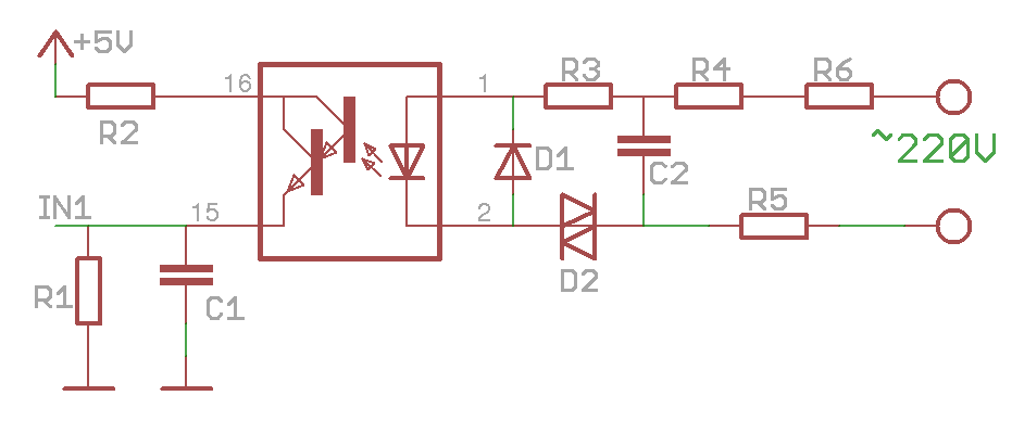
Explanations of the scheme: R4-R6 charge C2, when reaching ~ 35V, the dynistor is triggered, while R3 sets a current of 1-2 ma through the optocoupler. D1 protects the optocoupler against reverse polarity. R1 C1 average pulses.
Dry contact module
For connecting buttons, impulse counters, etc. The
input is activated when a short to earth.
There is a group galvanic isolation. Protection against voltage supply up to 30 V.
TTL I / O Module
This is a GPF with overvoltage protection on a polyfuse and a protective diode. Levels - 5V TTL.
“High side switch” module
Designed to control low-voltage load (the output delivers a voltage of 12-45 V, current up to 0.5A).
Here we decided to move away from the beloved principle of reinventing our bicycle and used a ready-made chip like the smart key BTS4880R . The chip has built-in protection against overvoltage, overheating, short circuit, etc.
Conclusion
In this article, we talked about the hardware solutions that are used in the expansion and input-output modules for the Wiren Board. In the next article we will tell about their use, why they are needed and how to use the controller as a whole.
PS
Our company is expanding, and we are looking to the team for another Linux system programmer - to develop software for our devices. The tasks are interesting, the conditions are flexible, we write the code immediately to the github . Details in the job description .