The talking prefix to the washing machine that does not violate the warranty
- Transfer
- Tutorial
Having purchased a washing machine with a seemingly mechanical control, the author and his blind wife Sue soon realized that they were mistaken. Instead of a command device, there was an encoder, the absolute position of which, for obvious reasons, is not connected with the selected program. The proven method — sticking tactile marks — no longer worked. It is unlikely that the author is familiar with the magazine "Young Technician", which means that he came to this decision independently - to read the status of the LEDs located around the encoder knob with photoresistors.
The video shows the essence of the problem, but it is already clear to anyone who knows what an encoder is:
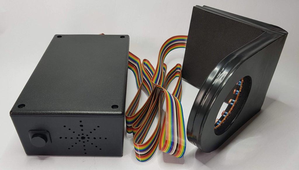
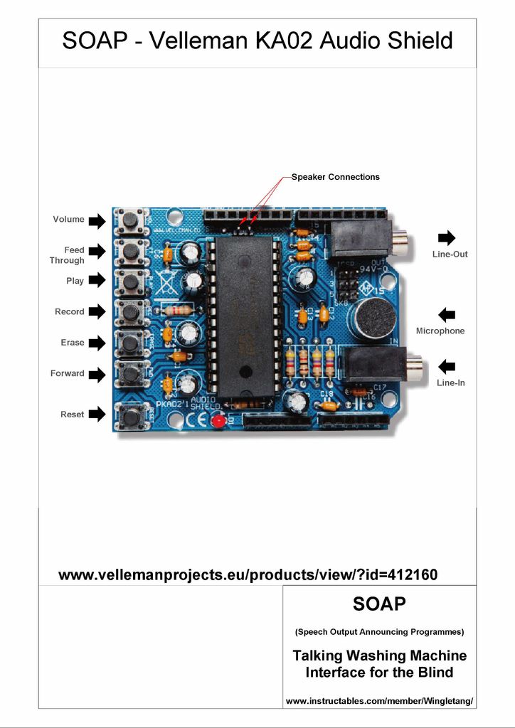
So, a device is born called SOAP - Speech Output Announcing Programs. For convenience, it is divided into two blocks. The first contains fourteen photoresistors arranged in a ring; its design depends on the geometry of the front panel of the machine. In the second is actually the "talker", the design of which is unchanged. Between themselves they are connected by a loop. Intervention in the washing machine does not occur, the warranty is not lost.
The device diagram is shown below. Connections to the shield for storing sound fragments are not shown, since it is simply mounted on an Arduino clone like any other shield. The number of photoresistors is equal to the number of programs on the machine. The pull-up resistors require selection so that when the LED in the car is on, the voltage on the photoresistor is less than 3 V, and when it is off, more.

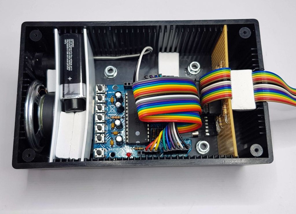
The device is powered by Krona via a latching button and a stabilizer located on an Arduino-compatible board. It’s more convenient, of course, to power the powerbank past this stabilizer, especially if you choose a board where it is not.
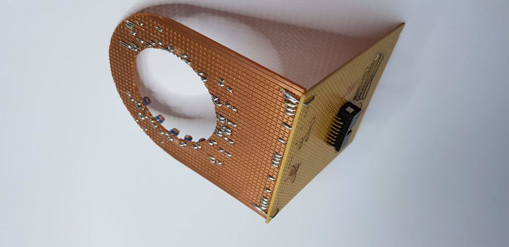
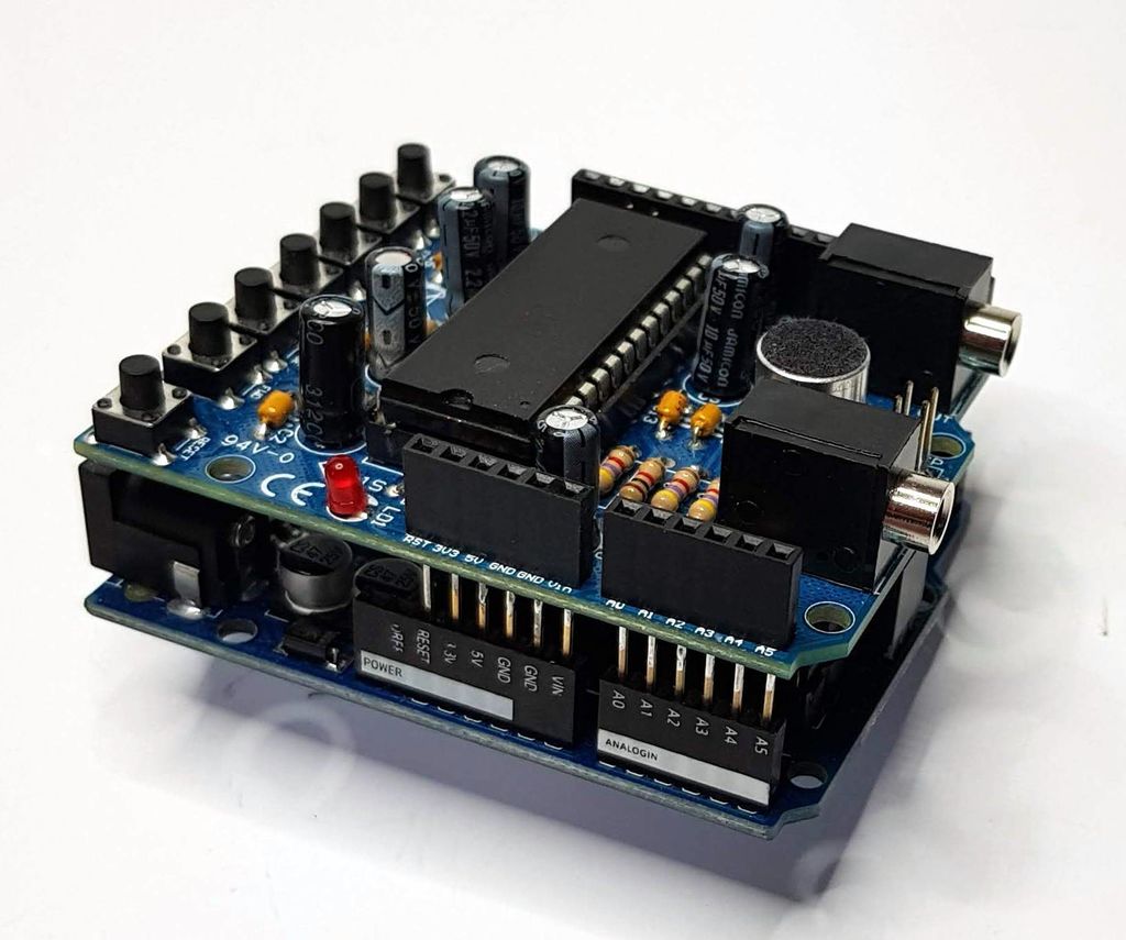
Without cases and a hood, the device looks like this: The

loop contains 16 conductors, of which 14 go to the photodiodes, and the remaining 2 to the common wire.
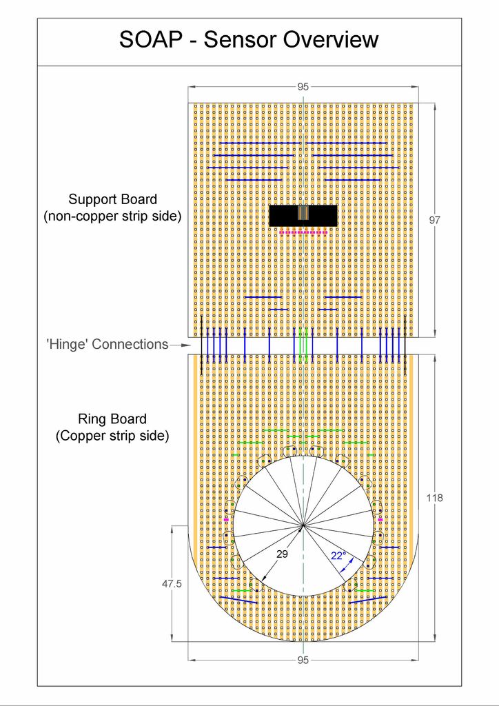
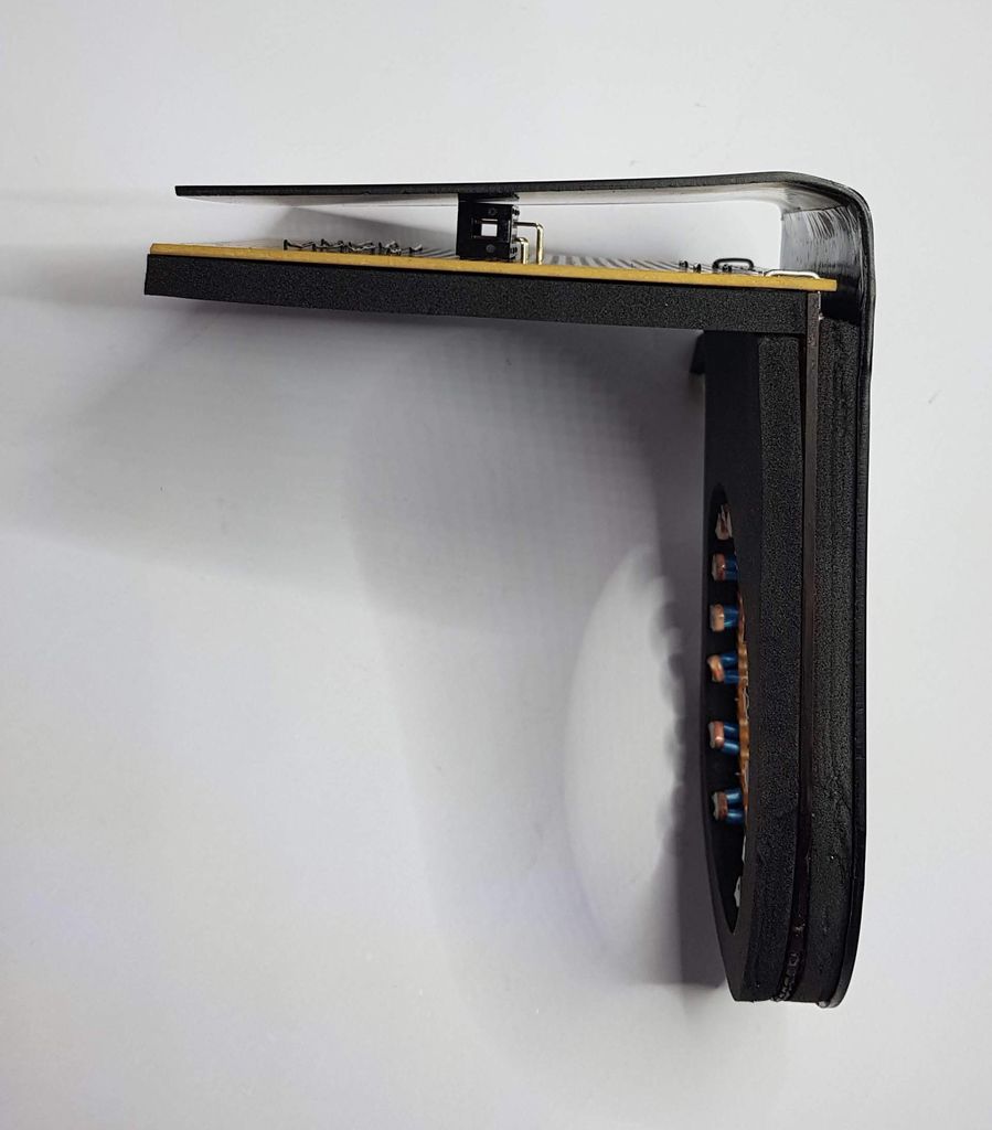
For the sensor, it is necessary to saw out two parts from the standard breadboard according to the drawing, then install photoresistors, jumpers and a connector (16 pins in 2 rows):
Assembly result ...
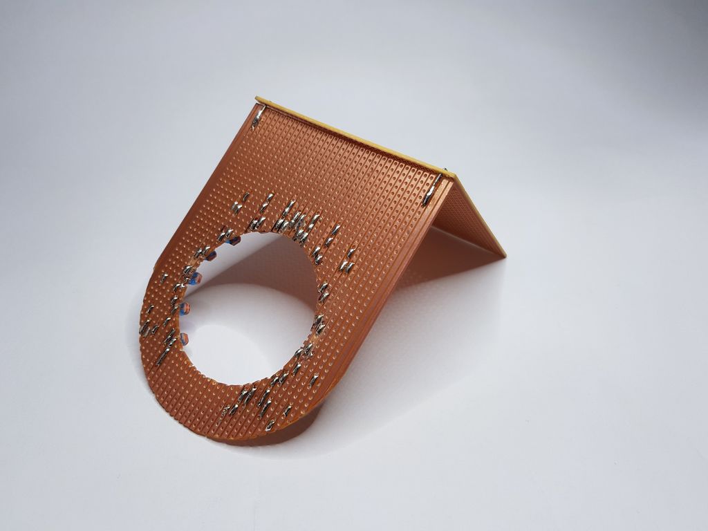
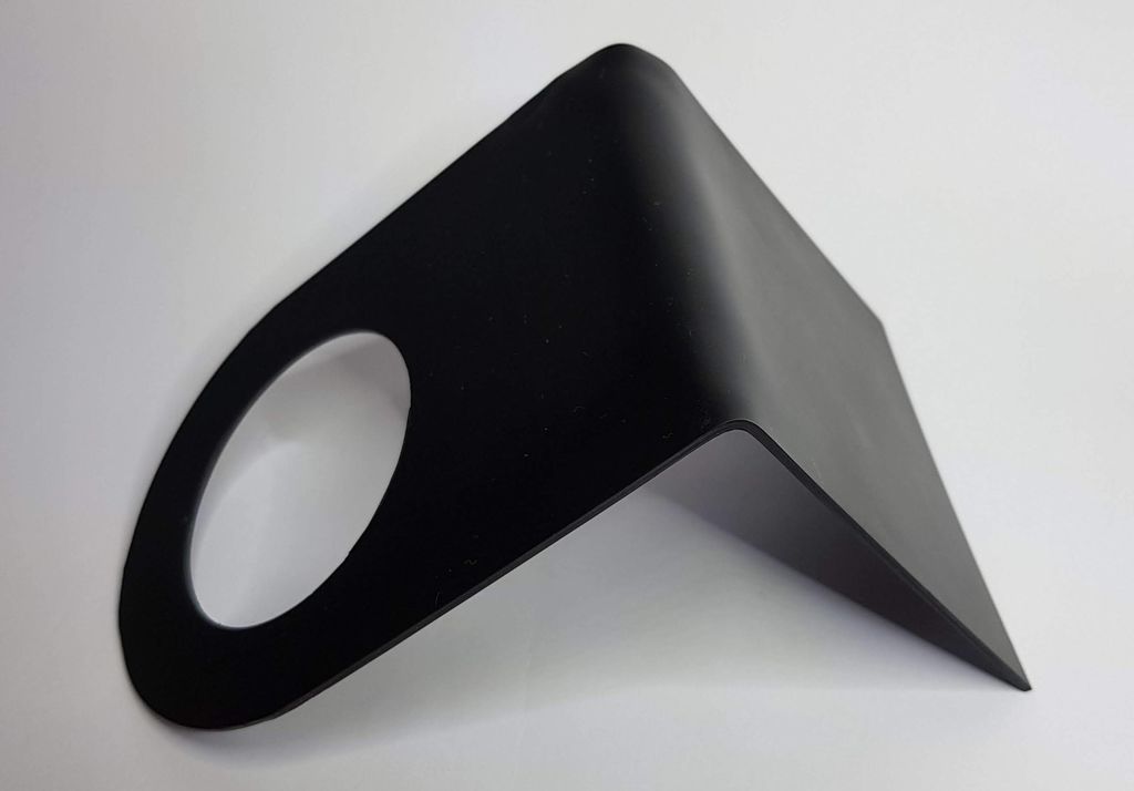
... paste on the front with soft, opaque material from the mouse pad, on the back with it, as well as thin black plastic sheet:

The following shows the methods of rounding cutting board with photoresistors and holes in it:


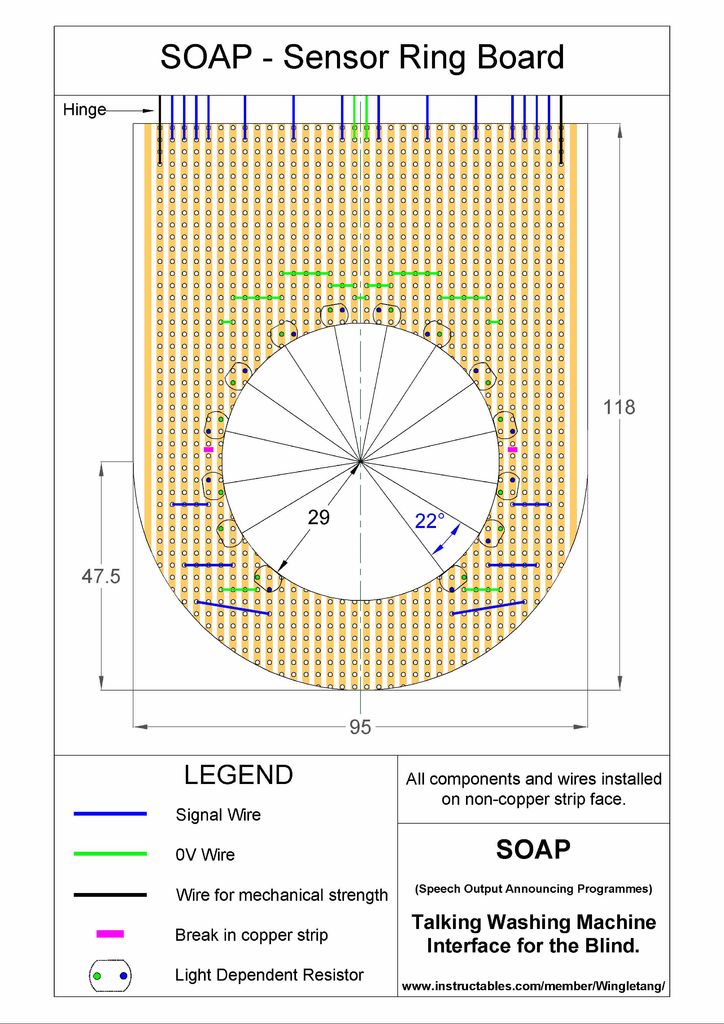
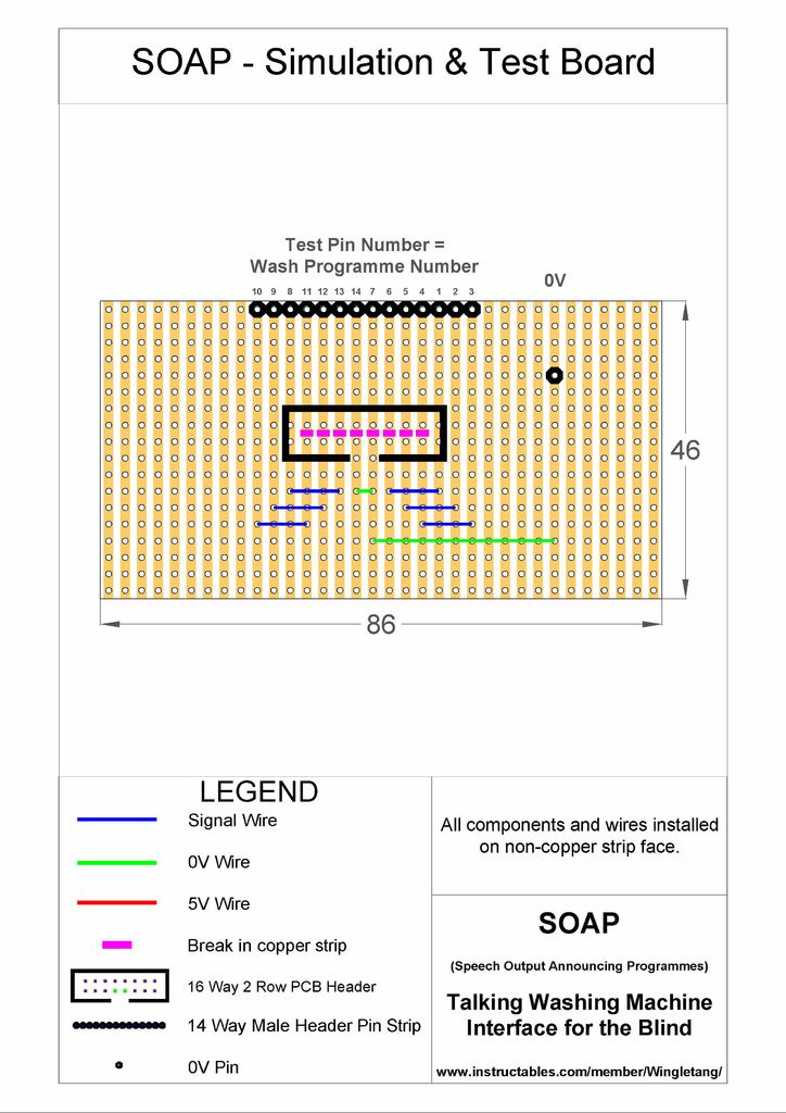
in the figure denote: blue - signaling jumper green - bridge, connected to the common wire, black - bridge imparting IU anicheskuyu stiffness, lilac - cut by the conductor tracks, ovals - photoresists. Photoresistors and jumpers must be soldered from the side opposite to the printed conductors.
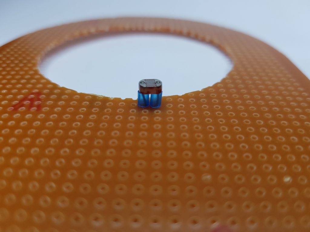
Put the tubes on the terminals of the photoresistors before soldering:

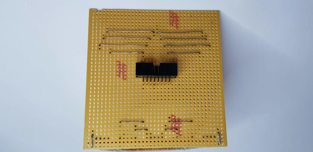
On the board drawing with the connector, the designations are the same:

Ready board:
Two boards connected together:
Circuit board gluing with porous material and thin plastic:

Parts before gluing:

After:
Now add the electrical tape from the sides:

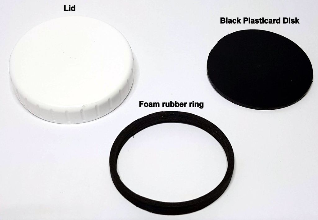
To the encoder handle be worn outside handle consisting of a lid ring (porous material) and the disk (thin plastic sheet):


The test card can operate in one of two modes:
- connected only loop from block photoresistors - can be measured x resistance with and without light
- only the Arduino loop is connected - you can simulate a decrease in the resistance of the photoresistors and check whether this leads to sound fragments.
Having put the first block on the washing machine, you need to connect its loop to the test board and, by switching the encoder modes, measure the resistance of the lighted photoresistors, thereby determining their scatter of parameters. The table shows the results obtained by the author and the results of selecting pull-up resistors based on them:

As can be seen from the table, the selection method is simple: the pull-up resistor should be slightly larger than the resistance of the illuminated photoresistor. If the LEDs in the washing machine are overloaded and will lose brightness over time, in the future a new selection of pull-up resistors may be required.
After setting up, it is necessary to replace the test board with a adapter board, into which the selected pull-up resistors are soldered, and connect both loops to it:

Now you can assemble the “talker”:
Phrases corresponding to the washing regimes must be recorded on the sound storage section. To do this:
- connect the dynamic head as shown in the drawing:
- put the board on the Arduino or its clone and apply power:
- by holding the play button, put the board in the recording mode and pronounce the phrase corresponding to the first mode, for example: “one - washing cotton”
- release the button
- short press on it to make the board lose the recorded phrase
- if you didn’t like it, rewrite it
- by pressing the “forward” button, go to the second cell
- write down the phrase corresponding to the second mode, for example: “two - economical washing of cotton”
So write down all fourteen phrases, remembering that the total should be no more than one minute, so fragments should not be made too long.
The next task is to adjust the start and end addresses of the fragments:

The sketch necessary for thistaken from the Velleman website and slightly redone. You need to fill it in Arduino, and then enter the number 1 in the serial port monitor. The first phrase will sound. If its beginning and end are defined correctly, nothing needs to be done, if it is wrong, adjust the corresponding addresses in the sketch (lines 14 and 15) and fill it again. Enter the number 2 and do the same with the second fragment, this time the lines 18 and 19 are subject to correction. The fragment numbers are hexadecimal, that is, instead of 10, the letter a must be entered in the serial port monitor, the letter b must be entered instead of 11, and so on.
Save the adjusted sketch - the addresses from it must be transferred to the working sketch . Here, each of the lines (from 14 to 27) contains both addresses - both the beginning and the end of the corresponding fragment.
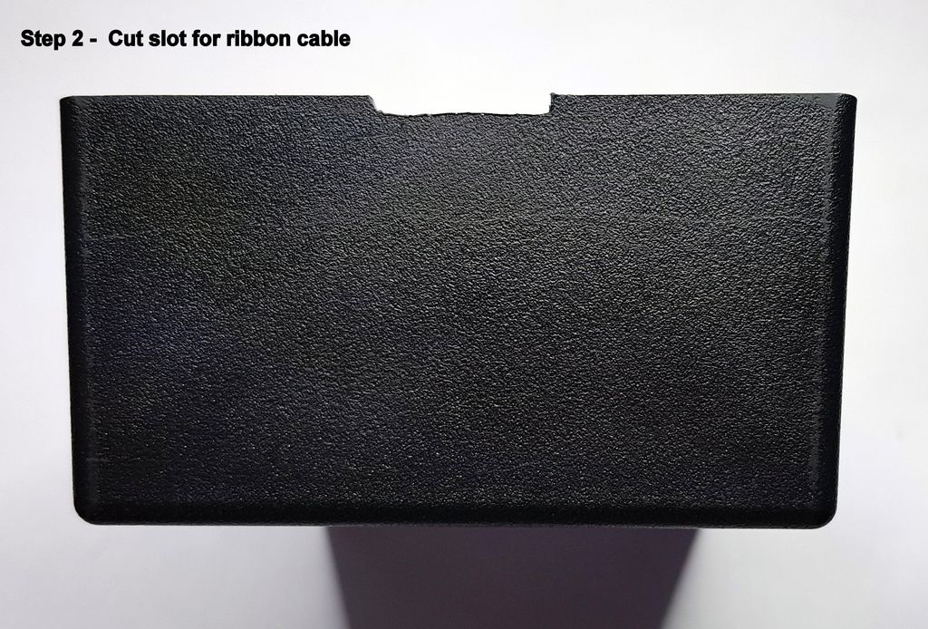
Now you can make holes in the “talker” case for the button with a fixation, a dynamic head and a loop:

Put the boards back in place:

And close the case:
However, you can first temporarily replace the adapter board with a test one again and listen to all the fragments, simulating the operation of photoresistors:
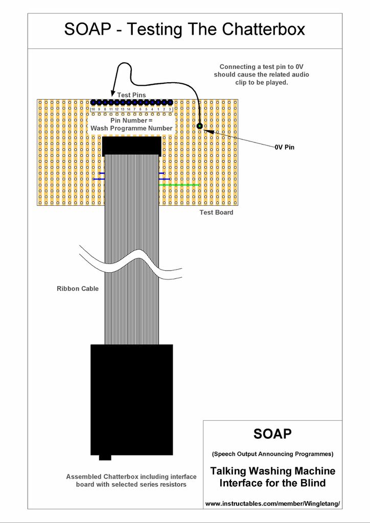
While the jumper is in place, the fragment will sound every three seconds.
Having returned the adapter board, we install the block with photoresistors on the washing machine:

And we check how everything works:
The nuts in the housing are not accidental. They allow you to fix the unit, pre-drilling holes in the bottom. Immediately after choosing the operating mode of the machine, the power of the talker must be turned off. The result of observing this rule: a year has passed, and the battery has not yet been replaced.