10 years on one battery: wireless humidity and temperature sensor
 Texas Instruments leads the way in many segments of the semiconductor market. Following the tradition, the company itself develops examples of the use of its electronic components and publishes materials on its website: theory, circuits, reference designs, training videos, etc. Electronic components and finished boards (development kits and tools) are also sold there. TI also has its own forum e2e.ti.com and supports a third-party resource www.43oh.com for development engineers and just amateurs. He is actively working with schools and colleges, teaching microcontroller programming even to junior high school students.
Nevertheless, our fans are not familiar with the remarkable products of this company. Most likely, this is due to the price and almost lack of materials in Russian, which limits the audience of amateurs who are familiar with semiconductor products from TI. There is also one unpleasant nuance - some things will not be missed by the customs of the Russian Federation, while others are not exported from the United States to the Russian Federation (and this is not the result of recent sanctions - “it happened”). However, there are ways to get what you need.
With this article I want to draw the attention of amateur developers to TI solutions, in particular, applicable to smart homes. A number of published articles on GT about smart home could borrow some interesting solutions. For example, the avs24rus article, Wireless Lighting-Sensor powered by CR2450, published, вызвала, запомнившееся мне, обсуждение в комментариях: «Как сделать так, чтобы датчик «поставить и забыть» на улице в условиях экстремальных минусовых температур? Аккумулятор, солнечная батарея, ионистор?
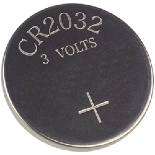
Предлагаю познакомиться с решением этой проблемы от TI на примере референс-дизайна TIDA-00484 TI Design: Датчик влажности и температуры на электронных компонентах TI может работать от популярного литиевого миниатюрного элемента питания CR2032более 10 лет в диапазоне –30°C… 60°C, что ограничено рабочим диапазоном CR2032, а не электронных компонент для коих этот диапазон равен –40°C… 85°C (для элемента питания BR2032 рабочий диапазон -30… 85 °C).
TIDA-00484 TI Design:
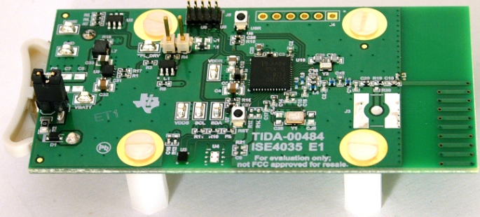
Пойдем от общего к частному. И сначала характеристики TIDA-00484 TI Design:
| Параметры | Описание |
| Source of power | CR2032 (240 mAh capacity) |
| Sensor type | Humidity and temperature |
| Temperature accuracy | ± 0.2 ° C |
| Relative humidity measurement accuracy | ± 3% |
| Measurement interval | One measurement per minute |
| Average power on | 3.376 mA |
| On time | 0.03 seconds |
| Average consumption at rest | 269.75 nA |
| Time at rest | 59.97 seconds |
| Estimated time from power supply | 11.90 years |
| Operating temperature range | –30 ° C to 60 ° C (limited by operating temperature range for CR2032) |
| Working conditions | Indoor and outdoor |
| The size | 3.81 cm × 7.62 cm |
Decide on the operating time from an autonomous power source. The system can be in two states: on and off. The duration and average current of each state are factors that determine the total duration of operation from the power source. The calculation of time is carried out according to the following formula:

where
- Battery life, estimated battery life in years
- Battery capacity, mAh
And the main parameters that affect the estimated battery life of the entire system are:
- Average power on, I ON , in mA
- On time, T ON , in seconds
- Average consumption at rest, I OFF , in nA
- Time at rest, T OFF , in seconds
Formula for Excel
Those interested can independently calculate in a table processor. Data in cells B9..B13
Battery capacity, mAh
B9 = 240
I on, mA
B10 = 3.376
T on, s
B11 = 0.03
I off, nA
B12 = 269.75
T off, s
B13 = 59.97
Battery life , years
= B9 / ((B10 * B11 + B12 * B13 * 0.000001) / (B11 + B13)) * 0.85 / 8760
Battery life it turned out 11.89
Battery capacity, mAh
B9 = 240
I on, mA
B10 = 3.376
T on, s
B11 = 0.03
I off, nA
B12 = 269.75
T off, s
B13 = 59.97
Battery life , years
= B9 / ((B10 * B11 + B12 * B13 * 0.000001) / (B11 + B13)) * 0.85 / 8760
Battery life it turned out 11.89
T OFF , fully controlled by the end user since in this case, the measurement system wakes up every minute and T OFF = 1 minute - T ON . The minimum time T ON can hardly be influenced by the user since it is determined by the time necessary to turn on the system, take measurements, transmit a radio packet and turn off the system.
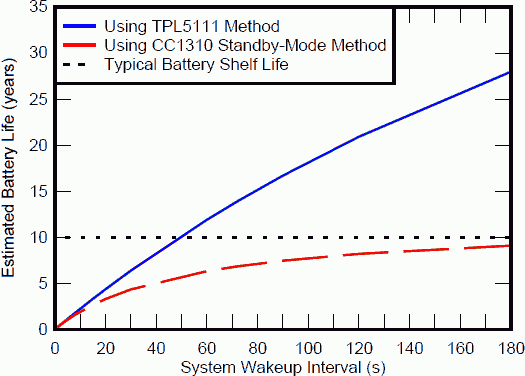
I offdefined as the average current consumed by the battery in the off state. This current is usually determined mainly by the leakage current through the capacitors and the operating current of the sensors and microcontroller systems providing sleep mode. Texas Instruments microcontrollers have long been known for ultra-low power consumption, to which competitors are only approaching, nevertheless, even such record-breaking efficiency is not enough to operate the device from the CR2032 element for 10 years. In this reference design, a method has been developed for measuring the relative humidity of the ambient air and temperature, which achieves an extremely long battery life due to the use of a timer in the operating cycle of the device.
The following graph shows two methods for organizing the device’s operating cycle — using the normal sleep mode of the microprocessor (red) and the system timer (blue). Black dashed line - CR2032 manufacturer declared life expectancy of 10 years.
Reference design is intended for use in:
- Industry
- Internet of Things (IoT)
- Building Automation
- Security systems
- HVAC sensors
- Smart Thermostats
- Battery Powered Systems
Let's see how the record efficiency of this prototype device is obtained. The device is built using the following components:
| Component | Description |
| TPS61291 | Step-up DC-DC voltage converter with bypass mode |
| Tpl5111 | System timer |
| TPS22860 | Load switch |
| HDC1000 | Humidity and temperature sensor |
| CC1310 | "Wireless Controller" |

CC1310 is a multi-core single-chip system, a low-cost, energy-efficient wireless controller, optimized for operations in the sub-GHz range. The high-performance transceiver is controlled by a dedicated Cortex-M0 processor core , which executes low-level protocols that are flashed into its ROM .
Top-level protocols are executed on a separate 32-bit Cortex-M3 processor core with a clock frequency of up to 48 MHz. The sensors are polled by an independent micropower controller (a 16-bit RISC processor capable of operating at frequencies from 32 kHz while the rest of the system is in sleep or standby mode), which can work with both analog and digital sensors.
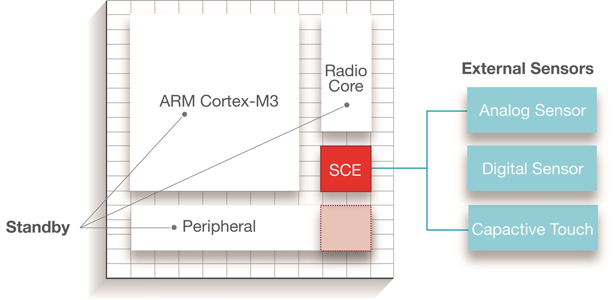
The Cortex M3 controller core has a rich set of peripherals and contains:
- temperature sensor;
- four general-purpose timer modules (2x16- or 1x32 bits with PWM mode);
- 8-channel 12-bit ADC (up to 200 qui / s);
- watchdog timer;
- analog comparator;
- UART, I2C;
- three SPIs (one of them is micropower);
- - AES module;
- - 10 ... 31 I / O lines (depending on the current configuration and case);
- - support for up to eight capacitive buttons
| Parameter | |
| Frequency range and supported modulation types | Sub 1 GHz: MSK, FSK, GFSK, OOK, ASK, 4GFSK, CPM (shaped 8 FSK) |
| Supported Protocols | Star Topology Networks: WMBUS, SimpliciTI |
| Flash, kB | 128 |
| RAM, kB | 20 |
| Supply voltage | 1.65 ... 3.8 |
| Temperature range, ° C | 40 ... 85 |
| Sensitivity 2.4 Kbps, dBm | -121 |
| Sensitivity 50 Kbps, dBm | -111 |
| Maximum output power at 868 MHz, dBm | fifteen |
| Maximum reception bandwidth, kHz | 400 |
| Minimum reception bandwidth, kHz | 40 |
| Data Rate, kMbit / s | up to 4 |
| power usage |
|
| Process technology | 65 nm |
Using the TPL5111 nanopower timer provides an obvious advantage since in fact, by the end of the life of the battery, the entire device can be replaced, for example, during the planned repair of premises, maintenance or modernization of equipment. If a smart home rarely needs more than two such devices (external and internal), then in the case of industrial facilities, buildings and ventilation systems, there will be much more such sensors and their periodic maintenance can be a serious expense.

If you calculate by the formula above, then the result will be 6.75 years.
The description of the working cycle is much shorter than the description of the design and its characteristics.
In the on state, after a certain interval, the TPL5111 timer supplies power to the TPS61291 boost converter, which raises the output voltage to 3.3 volts and to the TPS22860 load switch, which connects the increased output voltage to the rest of the system. After the appearance of the supply voltage, CC1310 via I2C receives the current temperature and relative humidity from the HDC1000 sensor, then transmits a “non-connected” data packet with this information (that is, without initializing and establishing a connection with any network node), and then signals to TPL5111 that the system can be turned off.
In the off state, the TPS22860 load switch completely disconnects part of the system (CC1310 and HDC1000 devices) from the lithium battery. The only current consumers from the lithium battery are the recharge and capacitor leakage currents of the lithium battery, the operating current of the timer TPL5111, the quiescent current TPS61291 to bypass mode, and the leakage current in the TPS22860 load switch.
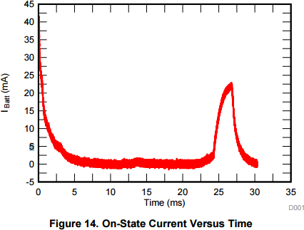
Graph of the current consumption from the battery when the system is turned on.
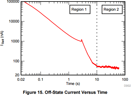
Graph of the current consumption from the battery in the off state of the system. Logarithmic scales.
A similar duty cycle can be used in other devices, for example, some sensors for water leakage, sensors for opening and closing doors, etc. where information is not required in real time, and the device’s power issue has priority.
Reference design can be found in detail in the documentation on the TI website:
- TIDA-00484. Humidity & Temp Sensor Node for Sub-1GHz Star Networks Enabling 10+ Year Coin Cell Battery Life
- TIDA-00374. TI Designs Humidity and Temperature Sensor Node for Sub-1GHz Star Networks Enabling 10+ Year Coin Cell Battery Life
- Taking power to a new low with the SimpleLink ULP wireless MCU platform
