The tale of how perfectionism controller reset me

I thought about buying a yogurt maker somehow. Yes, such that yogurt makes good and always the same quality. What is needed for this? Firstly, raw materials, secondly, accurate and stable temperature, thirdly, setting the cooking time. I began to choose and faced with the following ambush: cheap yogurt makers were unregulated. That is, inside the heating wire, and this wire, in fact, is connected to the network. What temperature will be inside the yogurt maker, depends on the hands of the collector, the ambient temperature, the phases of the moon and the depth of sleep of Cthulhu (Cthulhu fhtagn, by the way).
Of course, this situation did not suit me. And even more annoying was the situation around the yogurt makers, who, by their functions and parameters, suited me. For some reason, manufacturers of such yogurt makers believe that they are supplying space products to the market and the prices of such products should be appropriate. Strong mental anguish in the selection process drove me to the point that I expressed my indignation to my beloved wife about the inhumane pricing policy of yogurt makers and in the course of verbal outpourings I phrased the phrase “I’ll do it better for five hundred rubles,” after which then clicked ...
That was the backstory. And now the story. In the process of building a wonderful device, I ran into a bug. When the current temperature was displayed, the controller periodically went into reboot. That is, sometimes it worked for hours normally, and sometimes it was reset every few seconds. Since this began to happen after the ds18b20 sensor polling function was introduced into the firmware, it is natural that I turned to her for a bug search. And did not find anything. The stack did not break, the function did not write anything to its memory areas. In general, it worked, as it should be. Moreover, disabling this function removed the bug, which clearly indicated (as it seemed to me at that moment) the hero of the occasion. I thought that everything was to blame for the synchronization system.
Since I have a small stone (attiny2313a) and there aren’t enough timers for all lotions, I got out of the situation by writing a task manager that receives tasks and the required delay time from functions, puts them in the queue. Then, after counting down the necessary amount of time, he transfers control to them. I set the minimum delay time to 1 millisecond. Which allowed me to set delays from milliseconds to a minute. But if you look at the ds18b20 sensor datasheet, you will see that communication with the temperature sensor sometimes lasts more than 500 microseconds (reset and wait for presence).
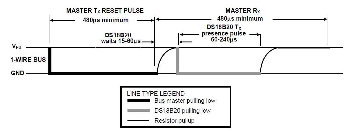
But what if, in the process, an interruption interferes with the communication function? There will be a time slot offset, due to which the controller will not be able to read the bit or correctly recognize the presence. I found a way out in using synchronization. The process is simple. When the sensor polling function sees that it will have long-term communication with the sensor, it sets up an interrupt in register B of timer 1 at the same time as the “time manager” interrupt, which is located in register A of timer 1. And since interrupts are processed in strict accordance with the address of the interrupt vector in the interrupt table, it turns out that after the synchronization process, the sensor polling function will receive control immediately after the interruption of the “time manager”.
Well, where can there be a bug? Yes everywhere. But personally, I thought that the problem could be at the intersection of interrupts. That is, when another one comes in during the execution of one interrupt. The cleaning of the code to solve this problem continued until I discovered that my actions led to the fact that the problem began to occur even with the sensor not connected. Having disabled the sensor polling function, I was convinced that now the controller resets do not depend on its operation. And then a brilliant guess struck me. Need to measure the voltage! The multimeter cheerfully reported that there are 4.2 volts on the controller. “Well, of course, BOD, I thought. And I connected external power to the board (before that I was content with USB power). The multimeter grunted quite a bit, which is 4.98 volts on the board. With a feeling of victory, I turned on the board to see the incredible. A bug was present! And it became even more vigorous. Now the controller was reset every couple of seconds, and sometimes in a split second. Searches continued with a vengeance and led to a function that displays information on the screen.
As you probably guessed, everything was fine with her, especially since after writing her, she was properly tested. And, nevertheless, everything said that my elusive bug lies in it. It turned out that the bug only occurs when displaying the current temperature page. Pages displaying power, start, time of the bug did not cause. Not finding anything that could cause this behavior, I decided to build on food. Namely, the fact that under normal voltage a bug occurred more often. By lowering the voltage, I found that at 3.8 volts on the controller, the latter works stably. The situation tore all the patterns. And then I remembered Ohm's law. Current is proportional to voltage. Is always? Not. On LEDs, this law does not work. It works more precisely, but with its gadgets.
The proportionality of the current through the diode is not the same as on a conventional resistor, because semiconductor devices are mostly non-linear. Remember at least a thyristor or a diode zener (zener diode). Here is a comparison of the current-voltage characteristic of the LED from the datasheet (black line) and the current-voltage characteristic of the resistive load (red line)
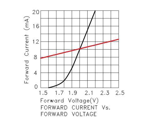
It is seen that for resistive loading Ohm's law is god and master. If the voltage increased by 10%, then the current will increase by the same 10%. But no one decree to the LED. If you raise the voltage on the LED by only 10% (from 2 volts to 2.2 volts), its current will jump 100%, that is, twice! But in my case, the main thing was that an increase in voltage also increased its drawdown at the moment of switching on the diode. And I had 32 diodes! Four seven-segment indicators with eight LEDs in each (seven segments and a point). They are connected to me not through multiplexing, but through shift registers because:
1. The conclusions of the attiny2313 controller were sorely lacking.
2. I am annoyed by their flickering when connected by multiplexing (perfectionism number of times)
3. Multiple controller resources are spent on output by multiplexing (perfectionism number two).
In addition, I connected shift registers with the function of turning off the screen for the duration of the display update (perfectionism number three). Why this feature has surrendered to me - I do not know. After all, the logic I have chosen can work up to a frequency of 100 MHz. Accordingly, the data can be pushed into it at the full frequency of the controller, which I have is 10 MHz. Well, who has time to notice the movement of bits in the bits of the indicator at such a frequency?
Move on. The power of my circuit is provided by the L7805 regulator, here is its connection diagram.
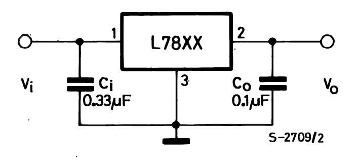
The regulator provides a current of 1A without any problems. At the output of the regulator there is a 0.1 microfarad capacitor, which, in theory, should smooth current fluctuations. Its charge at 5 volts is 0.5 microcoulomb. At 3.8 volts, the charge is respectively 0.38 microcoulomb. At 3.8 volts, the LEDs consume about 288 mA, and at 5 volts about 416 mA. Accordingly, when the voltage is raised from 3.8 volts to 5 volts, the charge stored by the capacitor will increase by 24%, but the current consumption will increase by more than 30 percent at the same time. The calculations are of course exemplary but show that the voltage drop in such a circuit is the greater the greater the supply voltage. At 3.8 volts, the drawdown was not critical for the controller. But at 5 volts the drawdown increased and began to reset the controller. And the controller was reset precisely on the temperature display page because
The solution was simple. In the code, you just had to comment out the lines for turning on and off the indicators sbi displayPort, offDispWire and cbi displayPort, offDispWire.
                ldi XL, videoMem
		cbi displayPort, shiftWire
		cbi displayPort, storageWire
		;sbi displayPort, offDispWire
		ZpushToDisplay:
		ldi temp2, 8
		ld temp, X+
		ZnextbitToDisplay:
		cbi displayPort, dataWire
		sbrc temp, 7
		sbi displayPort, dataWire
		sbi displayPort, shiftWire
		cbi displayPort, shiftWire
		lsl temp
		dec temp2
		cpi temp2, 0
		brne ZnextbitToDisplay
		cpi XL, videoMem+sizeVideoMem
		brne ZpushToDisplay
		sbi displayPort, storageWire
   		cbi displayPort, storageWire
		;cbi displayPort, offDispWire
Discharges have stopped. And the controller lived happily ever after.
Z.Y. the elusive bug search process pointed to another cant in the scheme. The fact is that the maximum dissipated power of the shift registers is about 0.5 watts, and the current through the power output or ground is about 70 milliamps. If the figure eight with a dot is displayed, the current through the shift register should be about 104 milliamps, which, as you know, is an excess. It's not that I did not take this moment into account. I have taken into account. But in the process of calculating the resistor for the LED, it succumbed to a minute weakness and forgot that the LED is a nonlinear element and to reduce the current through it twice it is not enough to double the resistance of the current-limiting resistor. In general, in any incomprehensible situation, see the CVC!