Nixie clock on one port - ATmega8
It's about such a thing as a clock on gas discharge indicators. Many have seen, or even read about them.
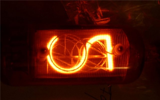
For those who don’t know, I explain: a gas discharge indicator is a bulb filled with rarefied gas, in our case neon. The cathodes are made in the form of symbols, and the anode in the form of a grid that surrounds them. If a high voltage is applied to the indicator, that is, about 200 volts, then a luminous region of a glow discharge is formed around the selected cathode.
So, the task was set: to make a clock on gas-discharge indicators, which in this case will duplicate all the information on the liquid crystal screen, and time will be received from the real-time clock microcircuit. AtMega8 microcontroller was chosen as the device’s core. This is a common microcontroller, tested by many, and a lot of different libraries are written on it, which helps a lot.
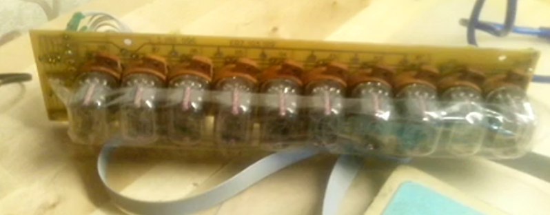
For the indication itself, I got a bar of as many as ten gas discharge indicators IN-12 and IN-15, so there can be no talk of a static indication.
We will deal with the device of the control module:
First we connect the ATmega8 microcontroller to the power supply, and pull the reset leg to the plus with a 10k resistor so that it does not work when it is not needed.
The LCD screen is connected via a six-wire bus, not counting power. I used the screen model wh1602a, but they differ from each other only in the order of the conclusions on the board, so replacing the screen is easy.
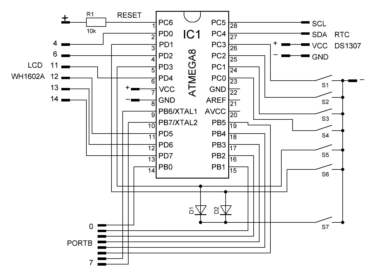
Next, go to the real-time clock chip. It should count the time, and, if necessary, report it to the microcontroller. I used the real-time clock module on the ds1307 chip. This method is much more accurate than calculating the time in the microcontroller itself, and besides, the time is saved when the clock is turned off, since they have their own battery. Like the BIOS clock on the motherboard.
To configure the clock, seven buttons are used, six of them directly go to the outputs of the microcontroller, and the seventh is connected by diodes to two outputs simultaneously. That is, when it is pressed, the program will think that these two buttons are pressed at once. This is done to save conclusions, the microcontroller, otherwise they simply are not enough.
Well, in the end, to display time for gas-discharge indicators, we have only one free port B. This is quite enough for a dynamic indication if you use two decoders.
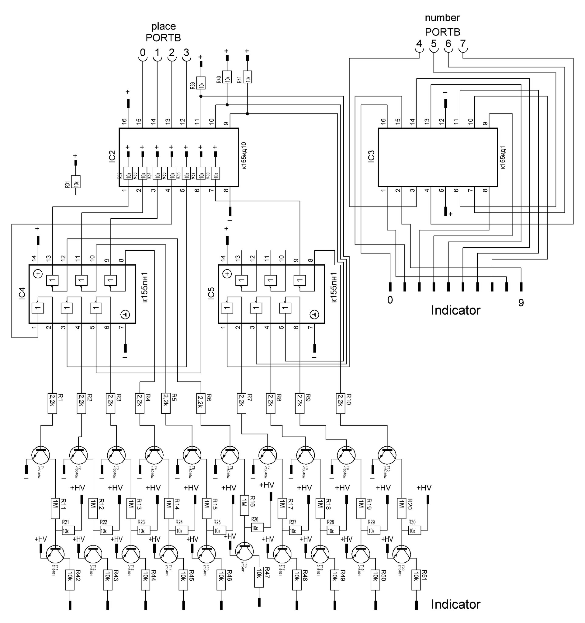
The first decoder is the well-known high-voltage logic chip k155id1. For it, the pins of port B are used from the fourth to the seventh. It receives the symbol number from the microcontroller on a four-bit bus, and opens the necessary output. Thus, it removes high voltage from the cathodes of the indicator, and resets it to minus, bypassing the microcontroller.
The development is carried out through the decryptor k155id10, connected to the pins of port B from zero to third. It works the same as the previous decoder, only with low voltage. Its findings have an open collector, so they are attracted to the plus by external resistors. Next, the signal is inverted using the “not” logic elements, and opens these two stages of transistors that protect the logic from high voltage. The scheme of these cascades was taken from an article on schem.net, where this process is described in great detail. Only the transistors I replaced with more affordable analogs. NPN transistor - kt604BM, PNP - 2n5401.

That is, you can use only one port of the microcontroller for indication on this screen. This saves both the outputs of the microcontroller and the processor time.
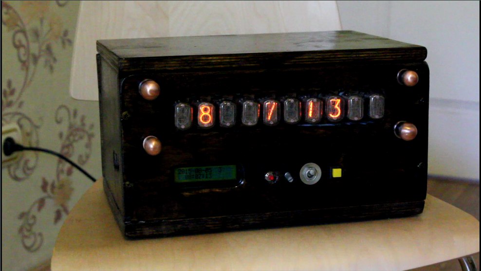
I designed the watch in such a case, there are two adapters in the case from the power supply, and the fan does not work, as you might think.

The photo shows: a control unit with a real-time clock, a step-up voltage converter, a module with high-voltage logic and transistors, and the bar itself with ten gas discharge indicators.
On the front of the case there are toggle switches to turn on the LCD screen backlight, to turn on the boost converter itself, the LCD screen contrast control, and the F button to switch modes.
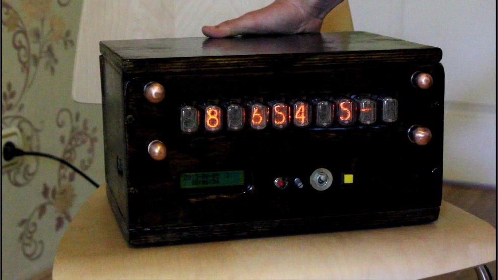
On the side are five buttons for setting the time.
The watch has three time display modes: time and date, only time, and time without displaying seconds.

Video with a demonstration of work (closer to its end):
I will leave all materials on the project (source codes, circuits, and printed circuit boards) here: yadi.sk/d/-Gw5HAAgiLJbE
Materials used : Transmotor isolation
article on schem.net: cxem.net/mc/mc187.php
Voltage converter article : e-kit.su/main/1562
For those who don’t know, I explain: a gas discharge indicator is a bulb filled with rarefied gas, in our case neon. The cathodes are made in the form of symbols, and the anode in the form of a grid that surrounds them. If a high voltage is applied to the indicator, that is, about 200 volts, then a luminous region of a glow discharge is formed around the selected cathode.
So, the task was set: to make a clock on gas-discharge indicators, which in this case will duplicate all the information on the liquid crystal screen, and time will be received from the real-time clock microcircuit. AtMega8 microcontroller was chosen as the device’s core. This is a common microcontroller, tested by many, and a lot of different libraries are written on it, which helps a lot.
For the indication itself, I got a bar of as many as ten gas discharge indicators IN-12 and IN-15, so there can be no talk of a static indication.
We will deal with the device of the control module:
First we connect the ATmega8 microcontroller to the power supply, and pull the reset leg to the plus with a 10k resistor so that it does not work when it is not needed.
The LCD screen is connected via a six-wire bus, not counting power. I used the screen model wh1602a, but they differ from each other only in the order of the conclusions on the board, so replacing the screen is easy.
Next, go to the real-time clock chip. It should count the time, and, if necessary, report it to the microcontroller. I used the real-time clock module on the ds1307 chip. This method is much more accurate than calculating the time in the microcontroller itself, and besides, the time is saved when the clock is turned off, since they have their own battery. Like the BIOS clock on the motherboard.
To configure the clock, seven buttons are used, six of them directly go to the outputs of the microcontroller, and the seventh is connected by diodes to two outputs simultaneously. That is, when it is pressed, the program will think that these two buttons are pressed at once. This is done to save conclusions, the microcontroller, otherwise they simply are not enough.
Well, in the end, to display time for gas-discharge indicators, we have only one free port B. This is quite enough for a dynamic indication if you use two decoders.
The first decoder is the well-known high-voltage logic chip k155id1. For it, the pins of port B are used from the fourth to the seventh. It receives the symbol number from the microcontroller on a four-bit bus, and opens the necessary output. Thus, it removes high voltage from the cathodes of the indicator, and resets it to minus, bypassing the microcontroller.
The development is carried out through the decryptor k155id10, connected to the pins of port B from zero to third. It works the same as the previous decoder, only with low voltage. Its findings have an open collector, so they are attracted to the plus by external resistors. Next, the signal is inverted using the “not” logic elements, and opens these two stages of transistors that protect the logic from high voltage. The scheme of these cascades was taken from an article on schem.net, where this process is described in great detail. Only the transistors I replaced with more affordable analogs. NPN transistor - kt604BM, PNP - 2n5401.
That is, you can use only one port of the microcontroller for indication on this screen. This saves both the outputs of the microcontroller and the processor time.
I designed the watch in such a case, there are two adapters in the case from the power supply, and the fan does not work, as you might think.
The photo shows: a control unit with a real-time clock, a step-up voltage converter, a module with high-voltage logic and transistors, and the bar itself with ten gas discharge indicators.
On the front of the case there are toggle switches to turn on the LCD screen backlight, to turn on the boost converter itself, the LCD screen contrast control, and the F button to switch modes.
On the side are five buttons for setting the time.
The watch has three time display modes: time and date, only time, and time without displaying seconds.
Video with a demonstration of work (closer to its end):
I will leave all materials on the project (source codes, circuits, and printed circuit boards) here: yadi.sk/d/-Gw5HAAgiLJbE
Materials used : Transmotor isolation
article on schem.net: cxem.net/mc/mc187.php
Voltage converter article : e-kit.su/main/1562