Source Code Quake III
- Transfer
[Translator's note: the translation of the first part of this article already have Habré, but its author for some reason did not complete the job.]
Renderer Quake III
The Quake III renderer was the evolutionary development of the Quake II hardware-accelerated renderer: the classic part is built on the architecture of “binary splitting” / “potentially visible sets”, but two new noticeable key aspects are added:
- Shader system built on top of the OpenGL 1.X fixed pipeline This was a great achievement for 1999. It provided a large space for innovation in the era to vertex, geometric, and fragment shaders that are ubiquitous today.
- Support for multi-core architecture: the OpenGL client-server model blocks some methods and the threading system partially solves this problem.
Architecture
The renderer is fully contained in
renderer.liband is statically linked to quake3.exe: 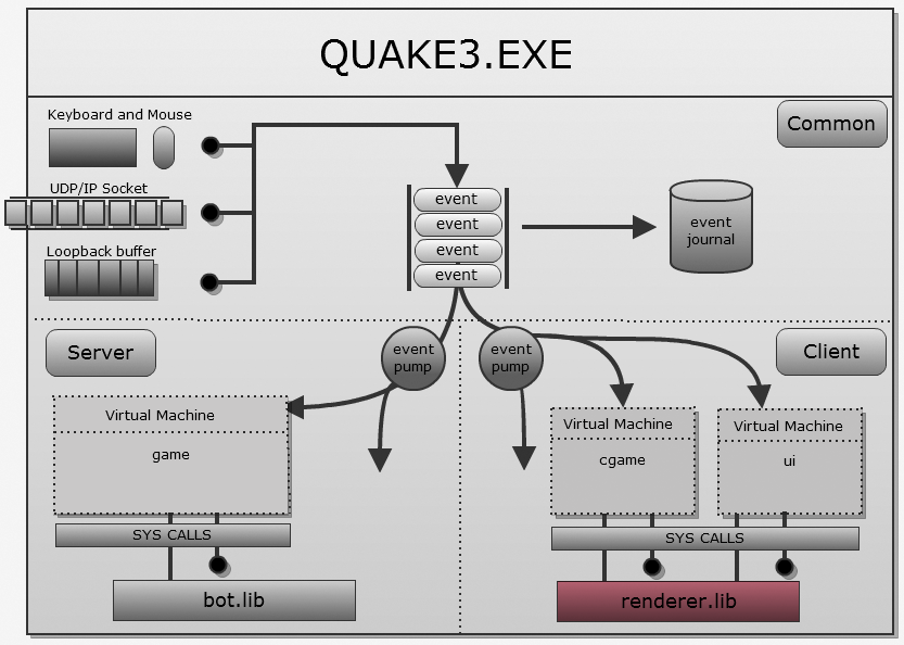
The general architecture repeats Quake Classic: it uses the famous combination of BSP / PVS / lighting maps:
- Preliminary processing:
- The game designer creates using QRadiant .map and saves it.
- q3bsp.exe cuts the map with binary space partitioning (BSP). I wrote about this in a review of Quake1's renderer.
- A portal system is generated from BSP: I wrote about this in an article about the Doom3 Dmap tool .
q3vis.exeuses a portal system and generates a PVS (potentially visible set) for each sheet. Each PVS is compressed and stored in a bsp file, as described in a previous article.- The portal system is cleared.
q3light.execalculates the lighting for each polygon on the map and saves the result as the texture of the irradiance map in a bsp file.- At this point, all pre-calculated data (PVS and lightmaps) are stored in a .bsp file.
- Lead time:
- The engine loads the map and bsp.
- When visualization is needed:
- The engine will unzip the PVS for the current sheet and determine what is actually visible .
- For each polygon, using multitexturing, he combines a lighting map with color.
The stage of multitexturing and lighting maps is clearly visible if you change the engine and display only one or the other:
Texture drawn by the level designer / artists:

Lighting map generated
q3light.exe: 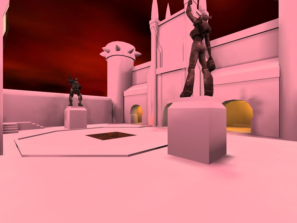
Final result when connecting using multitexturing at runtime:
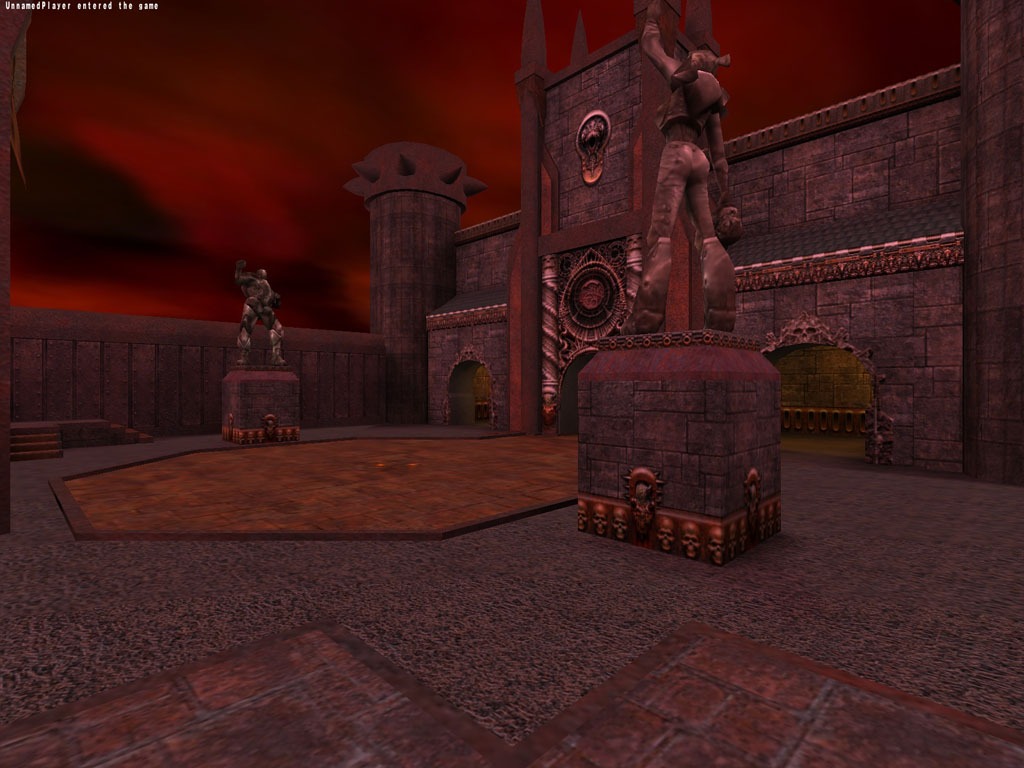
The rendering architecture was reviewed by Brian Hook (Brian Hook) at the Game Developer Conference in 1999. Unfortunately, the video from the GDC Vault is no longer available! [But it is on youtube .]
Shaders
The shader system is built on top of the OpenGL 1.X fixed pipeline, and therefore is very expensive. Developers can program vertex modifications, but also add texture passes. This is described in detail in the Quake 3 Shader bible shader bible:

Multi-core renderer and SMP (symmetric multiprocessing)
Многим неизвестно, что Quake III Arena была выпущена с поддержкой SMP с помощью cvariable
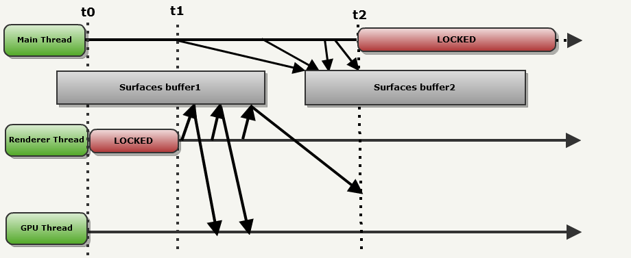
r_smp. Фронтэнд и бекэнд обмениваются информацией через стандартную схему Producer-Consumer. Когда r_smp имеет значение 1, рисуемые поверхности попеременно сохраняются в двойной буфер, расположенный в ОЗУ. Фронтэнд (который называется в этом примере Main thread (основным потоком)), попеременно выполняет запись в один из буферов, в то время как из другого выполняет чтение бекэнд (в этом примере называемый Renderer thread (потоком рендерера)).Пример демонстрирует, как всё работает:
t0-t1:
- Main thread решает, что отрисовывать, и записывает поверхности в surfacebuffer1.
- Для потока Renderer thread нет данных, поэтому он заблокирован.
- The GPU thread does nothing either.

t1-t2: processes start everywhere:
- The Main thread decides what will be visible in the next frame. It writes the surface to surfacebuffer2: this is a typical example of double buffering.
- Meanwhile, the Renderer thread makes an OpenGL call and patiently waits for the GPU thread to copy everything to a safe place.
- The GPU thread reads the surface from where the Renderer thread points.
Notice that in t2:
- Renderer thread is still transferring data to the GPU: using SurfaceBuffer1.
- Main thread has finished writing to SurfaceBuffer2 ... but cannot start writing to SurfaceBuffer1: it is locked
This case (when the Renderer thread blocks the Main thread) very often occurs when playing Quake III: We
demonstrate the restriction of blocking one of the OpenGL API methods.
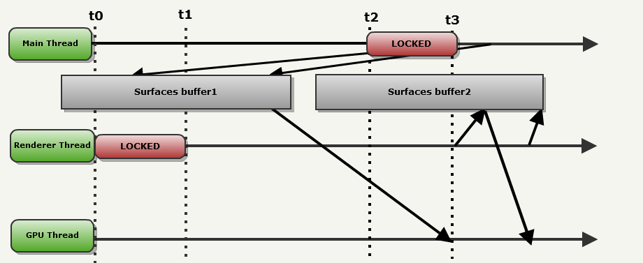
After t2:
- As soon as the Renderer thread finishes with SurfaceBuffer1 (t3), it starts uploading surfaces from SurfaceBuffer2.
- As soon as it is unlocked (in t3), the Main thread starts working in the next frame, writing to SurfaceBuffer1.
- In this configuration, the GPU is almost never idle.
Note: synchronization is performed through Windows Event Objects in winglimp.c (part with SMP acceleration at the bottom).
Network model
The Quake3 network model is without a doubt the most elegant part of the engine. At a low level, Quake III still abstracts the exchange of data with the NetChannel module, which first appeared in Quake World . The most important thing to understand:
In environments with a fast rhythm of change, any information that was not received during the first transfer is not worth re-sending, because it is still outdated.
Therefore, as a result, the engine uses UDP / IP: there are no TCP / IP traces in the code, because “reliable transmission” creates an unacceptable delay. The network stack has been enhanced with two mutually exclusive layers:
- Encryption using a pre-transmitted key.
- Compression using a pre-computed Huffman key.
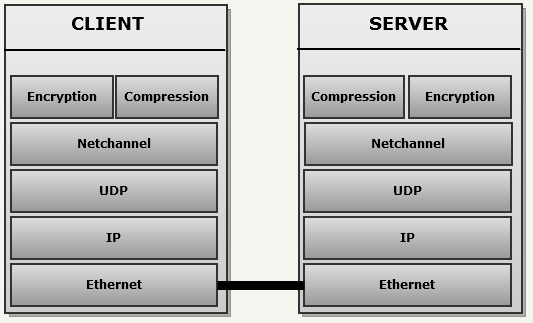
But the most amazing design is on the server side, where an elegant system minimizes the size of each UDP datagram and compensates for the unreliability of UDP: the snapshot history generates delta parquet using memory introspection.
Architecture
The client side in the network model is quite simple: the client sends commands to the server every frame and receives game status updates. The server side is a bit more complicated, because it must transmit the general state of the game to each client, taking into account the lost UDP packets. This mechanism contains three main elements:

- Master Gamestate is a general, true state of things. Customers send their teams to Netchannel. They are converted to event_t, which change the state of the game upon receipt by the server.
- For each client, the server stores the last 32 states of the game sent over the network in a circular array: they are called snapshots. The array is cycled using the famous binary mask trick, which I talked about in the Quake World Network article ( elegant solutions ).
- The server also has an “empty” state , with each field having a value of 0. It is used for delta snapshots that do not have “previous states”.
When the server decides to send the client an update, it uses all three elements in order to generate a message, which is then transmitted through NetChannel.
An interesting fact: storing such a number of game states for each player takes up a large amount of memory: according to my measurements, 8 MB for four players.
Snapshot System
To understand the snapshot system, I will give an example with the following conditions:
- The server sends the update to client Client1.
- The server tries to pass a state that has four fields to Client2 (three integer values for position [X], position [Y], position [Z] and one integer value for health).
- Communication is through UDP / IP: these messages are often lost on the Internet.
Frame 1 of the server:
The server received several updates from each client. They influenced the general state of the game (green). It is time to pass the state to Client1:
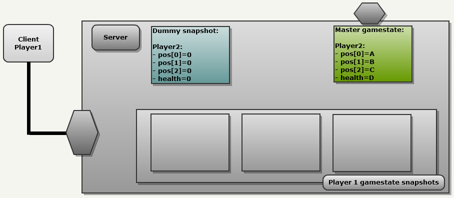
To generate a message, the network module ALWAYS does the following:
- Copy the general state of the game to the next slot in the client’s history.
- Compares it with another snapshot.
That is what we see in the following image.
- The general state of the game (Master gamestate) is copied with an index of 0 into the history of Client1: now it is called "Snapshot1".
- Since this is the first update, in the history of Client1 there are correct snapshots, therefore the engine uses an empty snapshot “Dummy snapshot”, in which all fields are reset. This results in a FULL update because each field is sent to NetChannel.
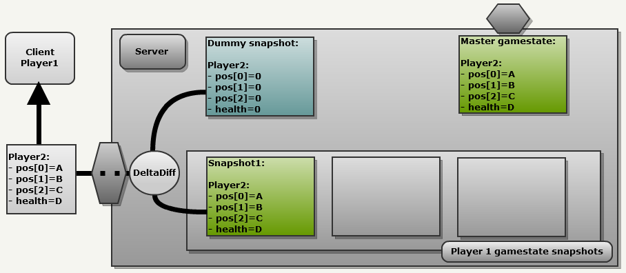
The most important thing here is to understand that if the client’s history does not contain the correct snapshots, the engine takes an empty snapshot to generate a delta message. This leads to a full update, the client sends a 132 bits (every field is preceded by a marker bit )
[1 A_on32bits 1 B_on32bits 1 B_on32bits 1 C_on32bits]. Server frame 2:
Now let's move a little to the future: here is the second server frame. As we can see, each client sent commands, and all of them affected the general state of the game Master gamestate: Client2 moved along the Y axis, so now pos [1] is equal to E (blue). Client1 also sent commands, but, more importantly, it confirmed the receipt of the previous update, so Snapshot1 was marked as confirmed (“ACK”):
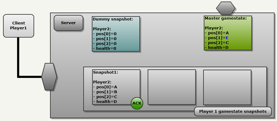
The same process is being performed:
- The general state of the game is copied to the following client history slot: (index 1): this is Snapshot2
- This time we have the correct snapshot in the client’s history (snapshot1). Compare these two snapshots
As a result, only a partial update is sent over the network (pos [1] = E). This is the beauty of this design: the process is always the same.
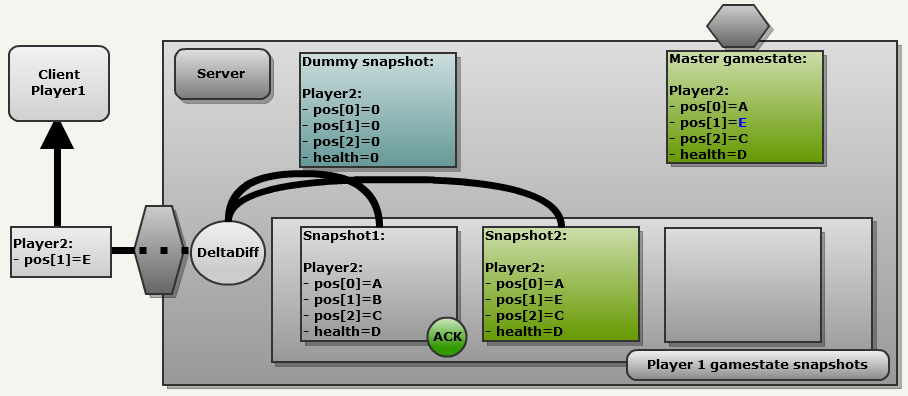
Note: since each field is preceded by a marker bit (1 = changed, 0 = no change), to partially update the above example uses 36 bits:
[0 1 32bitsNewValue 0 0]. Frame 3 of the server:
Let's take one more step forward to see how the system handles lost packets. Now we are in frame 3. Clients continue to send commands to the server.
Client2 suffered damage and health is now H. But Client1 did not confirm the latest update. The UDP server may have been lost, the client ACK may have been lost, but as a result, it cannot be used.
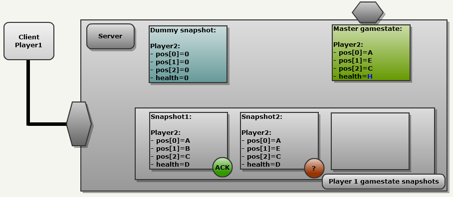
Despite this, the process remains the same:
- We copy the general state of the game into the following slot of the client’s history: (index 2): this is Snapshot3
- Compare the last valid confirmed snapshot (snapshot1).
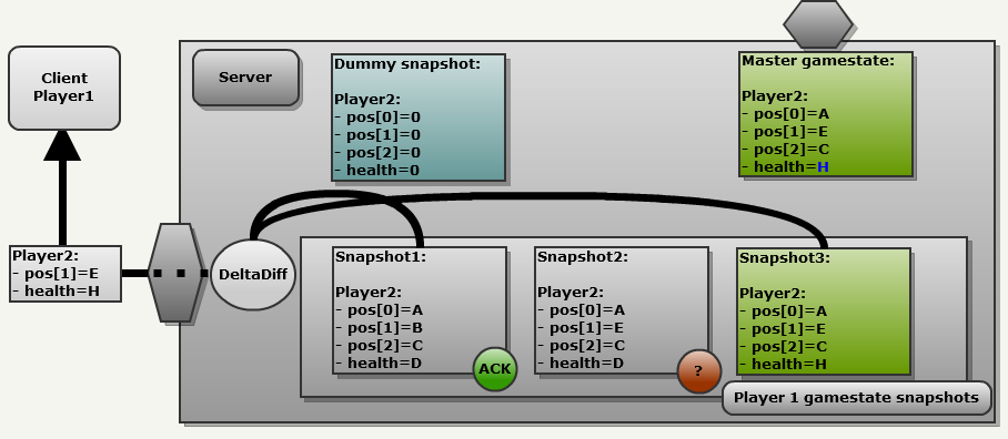
As a result, the message sends it partially and contains a combination of old and new changes: (pos [1] = E and health = H). Note that snapshot1 may be too outdated to use. In this case, the engine again uses the "empty snapshot", which leads to a complete update.
The beauty and elegance of the system lies in its simplicity. One algorithm automatically:
- Generates a partial or full update.
- Re-sends in one message the OLD information that was not received, and the NEW information.
Introspection C memory
You may wonder how Quake3 compares snapshots of introspection ... after all, C does not.
The answer is this: each field location for
netField_tis pre-created using an array and smart preprocessing directives: typedef struct {
char *name;
int offset;
int bits;
} netField_t;
// используем оператор преобразования в строку для сохранения типизации...
#define NETF(x) #x,(int)&((entityState_t*)0)->x
netField_t entityStateFields[] =
{
{ NETF(pos.trTime), 32 },
{ NETF(pos.trBase[0]), 0 },
{ NETF(pos.trBase[1]), 0 },
...
}The full code for this part is
MSG_WriteDeltaEntityfrom snapshot.c . Quake3 doesn't even know what it is comparing: it blindly uses index, offset, and size entityStateFieldsand sends differences over the network.Preliminary fragmentation
Having delved into the code, you can see that the NetChannel module cuts messages into blocks of 1400 bytes (
Netchan_Transmit), even though the maximum size of a UDP datagram is 65507 bytes. So the engine avoids breaking packets by routers when transmitting over the Internet, because most networks have a maximum packet size (MTU) of 1,500 bytes. Getting rid of fragmentation in routers is very important because:- Upon entering the network, the router must block the packet while it is fragmenting it.
- When leaving the network, the problems are even more serious, because you need to wait for all parts of the datagram, and then collect them with a lot of time.
Messages with reliable and unreliable transmission
Although the snapshot system compensates for UDP datagrams lost on the network, some messages and commands must be delivered necessarily (for example, when a player leaves the game or when the server needs the client to load a new level).
This binding is abstracted by the NetChannel module: I wrote about this in one of the previous posts .
Recommended Reading
One of the developers, Brian Hook, wrote a short article on the network model .
Unlagged author Neil “haste” Toronto also described her .
Virtual machine
If the previous engines gave the virtual machine only the gameplay, then idtech3 entrusts it with significantly more important tasks. Among other things:
- Visualization runs in the client virtual machine.
- The delay compensation mechanism is fully implemented in the client VM.
Moreover, its design is much more complex: it combines the protection / portability of the Quake1 virtual machine with the high performance of native Quake2 DLLs. This is achieved by compiling the bytecode into x86 commands on the fly.
An interesting fact: the virtual machine was originally supposed to be a simple bytecode interpreter, but the performance was very low. Therefore, the development team wrote a runtime x86 compiler. According to the .plan file dated August 16, 1999, this task was dealt with in one day.
Architecture
The Quake III virtual machine is called QVM. Three parts of it are constantly loaded:

- Client side: two virtual machines are loaded. Depending on the state of the game, messages are sent to one of them:
cgame: Receives messages in the battle phase. It only performs clipping of invisible graphics, predictions and controlsrenderer.lib.q3_ui: Receives messages in menu mode. Uses system calls to render menus.
- Server side:
game: always receives messages, executes game logic and usesbot.libAI to work.
QVM internals
Before we start describing the use of QVM, let's check how the bytecode is generated. As usual, I prefer to explain using illustrations and a brief accompanying text:
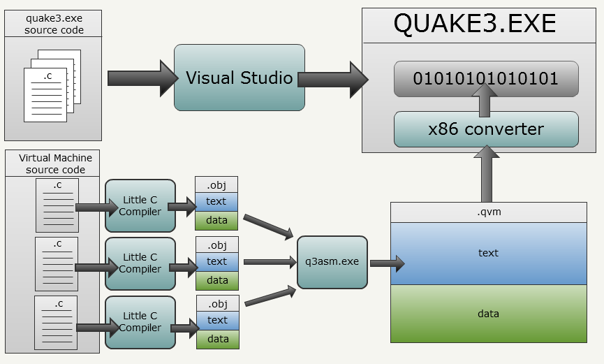
quake3.exeand its bytecode interpreter is generated using Visual Studio, but the VM bytecode uses a completely different approach:- Каждый файл .c (модуль трансляции) компилируется отдельно при помощи LCC.
- LCC используется со специальным параметром, благодаря которому выполняется вывод не в PE (Windows Portable Executable), а в промежуточное представление, которое является текстовой сборкой стековой машины. Каждый созданный файл состоит из частей
text,dataиbssс экспортом и импортом символов. - Специальный инструмент id Software под названием
q3asm.exeполучает все текстовые файлы сборок и собирают их вместе в файл .qvm. Кроме того, он преобразует всю информацию из текстового в двоичный вид (ради скорости, на случай, если невозможно применить нативные преобразованные файлы). Такжеq3asm.exeраспознаёт вызываемые системой методы. - After downloading the binary bytecode,
quake3.execonverts it to x86 commands (not required).
Inside LCC
Here is a concrete example starting with the function that we need to run in the virtual machine:
    extern int variableA;
    int variableB;
    int variableC=0;
    int fooFunction(char* string){
        return variableA + strlen(string);
    }
Stored in the translation module is
module.clcc.execalled with a special flag to avoid generating a Windows PE object and to output to the intermediate representation. This is the .obj LCC output file corresponding to the above C function: data
export variableC
align 4
LABELV variableC
byte 4 0
export fooFunction
code
proc fooFunction 4 4
ADDRFP4 0
INDIRP4
ARGP4
ADDRLP4 0
ADDRGP4 strlen
CALLI4
ASGNI4
ARGP4 variableA
INDIRI4
ADDRLP4 0
INDIRI4
ADDI4
RETI4
LABELV $1
endproc fooFunction 4 4
import strlen
bss
export variableB
align 4
LABELV variableB
skip 4
import variableAA few notes:
- The bytecode is divided into parts (
text,dataandbss): we clearly seebss(uninitialized variables),data(initialized variables) andcode(usually calledtext) - Functions are defined using the sandwich from
proc,endproc. - The intermediate representation of LCC is a stacked machine: all operations are performed on the stack and no assumptions about CPU registers are made.
- At the end of the LCC phrase, we have a group of files importing / exporting variables / functions.
- Each ad starts with the type of operation (eg,
ARGP4,ADDRGP4,CALLI4...). Each parameter and result is pushed onto the stack. - Import and export are here, so assembler can “link” translation modules together. Note that it is used
import strlenbecause neither q3asm.exe nor the VM interpreter accesses the standard C library,strlenis considered a system call and is executed by the virtual machine.
Such a text file is generated for each .c file in the VM module.
Q3asm.exe internals
q3asm.exereceives the text files of the intermediate LCC representation and collects them together in a .qvm file: 
Here you can notice the following:
- q3asm understands each of the import / export characters in text files.
- Some methods are predefined in the text file of system calls. You can see syscall for the client VM and for the server VM . System call symbols have attributes in the form of negative integer values so that the interpreter can recognize them.
- q3asm changes the presentation from text to binary in order to obtain space and speed, but nothing more, no optimizations are performed here.
- The first method to be assembled should be
vmMain, because it is a message manager. In addition, it must be in the0x2Dtext segment of the bytecode.
QVM: how does it work
Again, a picture showing a unique entry point and a unique exit point performing scheduling:

Some details:
Messages (Quake3 -> VMs) are sent to the virtual machine as follows:
- Any part of Quake3 can cause
VM_Call( vm_t *vm, int callnum, ... ). VMCallcan receive up to 11 parameters and writes each 4-bit value in the bytecode of the VM (vm_t *vm) from 0x00 to 0x26.VMCallwrites the message identifier to 0x2A.- The interpreter begins to interpret the opcodes in 0x2D (where he
q3asm.exewrote itvmMain). vmMainused to dispatch and route messages to the corresponding bytecode method.
A list of messages sent by the client VM and server VM is presented at the end of each file.
System calls (VM -> Quake3) are made like this:
- One by one, the interpreter executes the opcodes of the VM (
VM_CallInterpreted). - When it encounters an opcode
CALLI4, it checks the index of the method in int. - If the value is negative, then the call is system.
- The system call function pointer (
int (*systemCall)( int *parms )) is called with parameters . - The function pointed to
systemCallis used to dispatch and route the system call to the desired part of quake3.exe
The list of system calls provided by the client VM and server VM is at the top of each file.
An interesting fact: parameters always have very simple types, they are either primitive (char, int, float), or are pointers to primitive types (char *, int []). I suspect this is done to minimize the problems of struct communication between Visual Studio and LCC.
An interesting fact: Quake3 VM does not perform a dynamic connection, so the developer of the QVM mod did not have access to any libraries, even the standard C library (strlen, memset are here, but they are actually system calls). Some managed to emulate them using a predefined buffer: Malloc in QVM .
Unprecedented freedom
Thanks to the transfer of functions to the virtual machine, the modder community has received much greater opportunities. In Neil Toronto's Unlagged , the predictive system was rewritten using "backward matching ."
Performance issue and solution
Because of such a long tool chain, developing VM code was difficult:
- The toolchain was slow.
- Toolchain was not integrated into Visual Studio.
- Building QVM required the use of command line tools. This interfered with the development process.
- Due to the large number of tool chain elements, it was difficult to find the parts responsible for the errors.
Therefore, idTech3 also had the ability to load native DLLs for parts of the VM, and this solved all the problems:

In general, the VM system was very flexible, because the virtual machine has the ability to execute:
- Interpreted bytecode
- Bytecode compiled into x86 commands
- Code Compiled into Windows DLL
Recommended Reading


Artificial Intelligence
The modder community has written bot systems for all previous idTech engines. At one time, two systems were quite famous:
- For Quake1 was Omicron .
- For Quake2 they wrote Gladiator.
But for idTech3, the bot system was a fundamental part of the gameplay, so it had to be developed within the company and it had to be present in the game initially. But serious problems arose during development:
Source : page 275 of the book “Masters of Doom”:
К тому же не был готов фундаментальный ингредиент игры — боты. Боты — это персонажи, управляемые компьютером. Правильный бот должен хорошо вписываться в игру, дополнять уровни и взаимодействовать с игроком. Для Quake III, которая была исключительно многопользовательской игрой, боты оказались неотъемлемой частью игры в одиночку. Они должны были стать безусловно сложными и действовать подобно человеку.
Кармак впервые решил передать задачу создания ботов другому программисту компании, но потерпел неудачу. Он снова посчитал, что все, как и он, целеустремлённы и преданы работе. Но Кармак ошибался.
Когда Грэм попытался остановить работу, обнаружилось, что боты совершенно неэффективны. Они не вели себя, как люди, и были просто ботами. Команда начала паниковать. Это был март 1999 года, и причины для страха конечно же были.
Архитектура
As a result, Jean-Paul van Waweren (Mr.Elusive) worked on the bots, and this is funny, because he wrote Omicron and Gladiator. This explains why part of the server code of the bots is separated into a separate project
bot.lib: 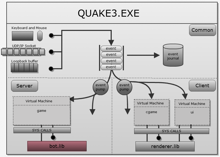
I could write about it, but Jean-Paul van Waveren himself wrote a
103-page work with a detailed explanation. Moreover, Alex Champagne (Alex J. Champandard) created a review of the code of the bot system , which describes the location of each module mentioned in the work of van Waverin. These two documents are enough to understand Quake3 AI.
