Duke Nukem 3D Source Code Analysis: Part 1
- Transfer

After leaving work at Amazon, I spent a lot of time reading great source code.
Having dealt with the incredibly wonderful idSoftware code , I set about one of the best games of all time : Duke Nukem 3D and its engine called " Build ". It turned out to be a difficult experience: the engine itself is of great importance and is highly valued for its speed, stability and memory consumption, but my enthusiasm came up against the source code, which was contradictory in terms of orderliness, compliance with recommendations and comments / documentation. While reading the code, I learned a lot about the legacy code and what allows the software to live long. As usual, I reworked my notes
to the article. I hope she inspires you to read the source code and improve your skills.
I want to thank Ken Silverman for the proofreading of this article: his patience and conscientious answers to my letters were important to me.
Origin
Duke Nukem 3D - not one, but two code bases:
- Build engine : provides rendering, networking, file system and caching services.
- Game module: uses Build services to create a game.
Why was this separation necessary? Because in 1993, when development began, only a few people had the skills and zeal needed to create a good 3D engine. When 3D Realms decided to write a game that would compete with Doom , it needed to find powerful technology. And at that moment Ken Silverman appears on the scene.
According to his well-documented website and interview , Ken (at the time he was 18) wrote a 3D engine at home and sent a demo to 3D Realms for evaluation. They considered his skills promising, and made an agreement:
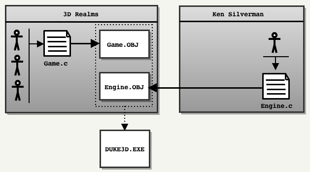
Silverman will write a new engine for 3D Realms, but will retain the source code.
It will provide only binary static library (
Engine.OBJ) with the header file Engine.h. For its part, the 3D Realms team will take over the work on the game module ( Game.OBJ) and will release the final executable DUKE3D.EXE. Unfortunately, the source code of both parts of the game was not open at the same time:
- The source code for the engine was released by Ken Silverman on June 20, 2000.
- The source code for the game module was released by 3D Realms on April 1, 2003.
As a result, the full source code became available only 7 years after the release of the game.
Interesting fact: the name of the engine " Build " was chosen by Ken Silverman when creating the catalog for the new engine. He used the thesaurus to find synonyms for the word "Construction" .
First contact
 Since the source code was released a long time ago (it was intended for the Watcom C / C ++ compiler and DOS systems), I tried to find something similar to Chocolate doom : a port that faithfully reproduces the Duke Nukem 3D gameplay as it was in 90 x, and seamlessly compiling on modern systems.
 It turned out that the Duke Nukem source code community is no longer too active: many ports are outdated again, some are for MacOS 9 PowerPC. Only one is still supported ( EDuke32 ), but it has evolved too much compared to the original code.
As a result, I started working with xDuke , although it did not compile on Linux and Mac OS X (which precluded the use of Xcode: a great IDE for reading code and profiling).
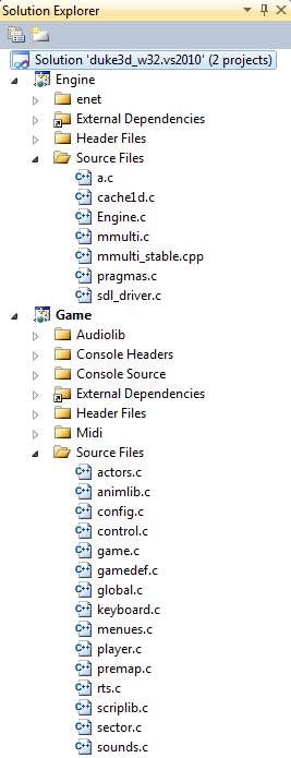
xDuke, made with Visual Studio, faithfully reproduces the original code. It contains two projects: Engine and Game. The Engine project is compiled into a static library (
Engine.lib), and the Game project (containing the method main) is linked to it to generate it duke3D.exe. When you open VS, the engine sources look rather unfriendly due to complex file names (
a.c, cache1d.c). These files contain something hostile to the eye and brain. Here is one of many examples in the Engine.c file (line 693) :if ((globalorientation&0x10) > 0) globalx1 = -globalx1, globaly1 = -globaly1, globalxpanning = -globalxpanning;
if ((globalorientation&0x20) > 0) globalx2 = -globalx2, globaly2 = -globaly2, globalypanning = -globalypanning;
globalx1 <<= globalxshift; globaly1 <<= globalxshift;
globalx2 <<= globalyshift; globaly2 <<= globalyshift;
globalxpanning <<= globalxshift; globalypanning <<= globalyshift;
globalxpanning += (((long)sec->ceilingxpanning)<<24);
globalypanning += (((long)sec->ceilingypanning)<<24);
globaly1 = (-globalx1-globaly1)*halfxdimen;
globalx2 = (globalx2-globaly2)*halfxdimen;Note: if the file / variable name contains a number, then this is quite possibly not a very good name!
Interesting fact: the last part of the code
game.ccontains a draft script Duke V ! Note: xDuke uses SDL, but the cross-platform API has lost the advantage of WIN32 (
QueryPerformanceFrequency)timers. It seems that the used SDL Timer is too inaccurate to emulate a frequency of 120 Hz in DOS.Assembly
By understanding the SDL and the location of the DirectX header / libraries, you can compile the code in one click. It is very nice. The last thing left is to get the resource file
DUKE3D.GRP, and the game will start ... well, or something like that. It looks like the SDL has some problems with the palette in Vista / Windows 7: 
Running in windowed mode (or better in Windows 8) seems to solve the problem:
Process immersion
Now the game is working. In a few seconds, Build appears in all its splendor, demonstrating:
- Sloping ceilings
- Realistic surroundings
- Free fall
- The feeling of true 3D.
The last point is probably the most affected players in 1996. The dive level was unsurpassed. Even when technology reached its limit due to two-dimensional maps, Todd Replogle and Allen Blum implemented “sector effectors” that allowed the player to teleport and enhance the feeling of immersion in the three-dimensional world. This function is used in the legendary LA Meltdown map:
When a player jumps into the ventilation shaft:


Sector effectors trigger and teleport the player to a completely different place on the map before landing:


Good games slowly age, and Duke Nukem was no exception: twenty years later She's still incredibly fun to play. And now we can also study its source!
Engine Library Overview

The engine code is in one file of 8503 lines and with 10 main functions (
Engine.c) and in two additional files:cache1.c: contains a virtual file system (sic!) and caching system procedures.a.c: C implementation of recreated reverse engineering code that was highly optimized x86 assembler. The code works, but reading it is a huge torment!
Three translation modules and several functions make up a high-level architecture that is difficult to understand. Unfortunately, these are not the only difficulties the reader will encounter. I dedicated an entire section to the
internals of the Build engine (see below).
Game Module Overview

The game module is built entirely on top of the engine module, system calls of the operating system are used by the process. Everything in the game is done through Build (rendering, loading resources, file system, caching system, etc.). The only exceptions are sounds and music, they are fully related to the Game .
Since I was more interested in the engine, I didn’t understand much here. But in this module you can see more experience and organization: 15 files divide the source code into understandable modules. It even has an
types.h(initiator stdint.h) to improve portability. A couple of interesting points:
game.cIs a monster of 11,026 lines of code.- There
menu.care 3,000 lines with a “switch case”. - Most methods have “void” parameters and return “void”. Everything is done through global variables.
- Method names do not use camelCase or the NAMESPACE prefix.
- The module has a good parser / lexical analyzer, although token values are transmitted via decimal values instead
#define.
In general, this part of the code is easy to read and understand.
Inherited source code
Looking at the infinite number of ports generated by Doom / Quake, I always wondered why there are so few Duke Nukem 3D ports. The same question arose when the engine was ported to OpenGL only after Ken Silverman decided to do it on his own.
Now that I have looked at the code, I will venture to explain this in the second part of this article
Chocolate Duke Nukem 3D
I love this engine and love the game, so I couldn’t leave it as it is: I created Chocolate Duke Nukem 3D , a port of “vanilla” source code, trying to achieve two goals in this way:
- Training: easy to read / understand and portability.
- Credibility: the gameplay should be similar to the one that we saw in 1996 on our 486s.
I hope this initiative helps to inherit the code. The most important modifications will be described in the second part of the article.
Build engine internals
Build was used in Duke Nukem 3D and many other successful games such as Shadow Warrior and Blood . At the time of release on January 29, 1996, he destroyed the Doom engine withinnovative features:
- Destructible surroundings
- Sloping floors and ceilings
- Mirrors
- The ability to look up and down
- The ability to fly, crawl and swim underwater
- Voxel objects (appeared later in “Blood”)
- Real immersion in 3D (thanks to teleporters).
The crown was taken from him in June 1996 by Quake, launched on powerful Pentiums ... but for several years Build provided high quality, freedom of designers and, most importantly, good speed on most computers of that time.
Essential Concept: Portal System
Most 3D engines split game cards using the Binary Space Partition or the Octree. Doom, for example, pre-processed each card with a time-consuming method (up to 30 minutes), resulting in a BSP tree that allowed:
- Sort walls
- Determine the position
- Detect collisions.
But for the sake of speed, I had to make concessions: the walls could not move . Build removed this restriction, he did not pre-process the cards, but instead used the portal system :


On this map, the game designer drew 5 sectors (above) and connected them together, marking the walls as portals (below).
As a result, the Build world database has become ridiculously simple: one array for sectors and one array for walls.
  Sectors (5 entries): Walls (29 entries):
  =================================================== ======================
  0 | startWall: 0 numWalls: 6 0 | Point = [x, y], nextsector = -1 // Wall in sector 0
  1 | startWall: 6 numWalls: 8 .. | // Wall in sector 0
  2 | startWall: 14 numWalls: 4 .. | // Wall in sector 0
  3 | startWall: 18 numWalls: 3 3 | Point = [x, y], nextsector = 1 // Portal from sector 0 to sector 1
  4 | startWall: 21 numWalls: 8 .. | // Wall for sector 0
  ============================== .. | // Wall for sector 0
                                               .. |
                  The first wall of the sector 1 >> 6 | Point = [x, y], nextsector = -1
                                                7 | Point = [x, y], nextsector = -1
                                                8 | Point = [x, y], nextsector = -1
                                                9 | Point = [x, y], nextsector = 2 // Portal from sector 1 to sector 2
                                               10 | Point = [x, y], nextsector = -1
                                               11 | Point = [x, y], nextsector = 0 // Portal from sector 1 to sector 0
                                               12 | Point = [x, y], nextsector = -1
                The last wall of the sector 1 >> 13 | Point = [x, y], nextsector = -1
                                               .. |
                                               28 | Point = [x, y], nextsector = -1
                                               =============================================
Another misconception regarding Build - it does not emit rays: the vertices are first projected into the player’s space, and then a column / distance is generated from the viewpoint.
Duty Cycle Overview
High-level description of the frame rendering process:
- The game module transmits to the engine module the sector from which the rendering should begin (usually this is the player's sector, but there may also be a sector with a mirror).
- The engine module bypasses the portal system and visits the sectors of interest . In each sector visited:
- Walls are grouped into sets called groups (“bunch”). They are saved on the stack.
- The sprites that are visible in this sector are determined and saved onto the stack.
- Groups are processed in order from near to far: solid walls and portals are rendered.
- Rendering stops: waiting for the game module to update visible sprites.
- All sprites and transparent walls are rendered in order from far to near.
- Buffers are switched.
Here are each of the steps in the code:
   //  1. При каждом перемещении игрока его текущий сектор должен быть обновлён.
   updatesector(int x, int y, int* lastKnownSectorID)
   displayrooms()
   {
      // Рендеринг сплошных стен, потолков и полов. Заполнение списка видимых спрайтов (они при этом НЕ рендерятся).
      drawrooms(int startingSectorID)
      {
          // Очистка переменной "gotsector", битового массива "visited sectors".
          clearbufbyte(&gotsector[0],(long)((numsectors+7)>>3),0L);
          // Сброс массивов umost и dmost (массивы отслеживания отсечения).
          // 2. Посещение секторов и порталов: построение списка групп ("bunch").
          scansector(startingSectorID)
          {
             // Посещение всех соединённых секторов и заполнение массива BUNCH.
             // Определение видимых спрайтов и сохранение ссылок на них в tsprite, spritesortcnt++
          }
          //На этом этапе уже назначен numbunches и сгенерирован bunches.
          // Итерация стека групп. Это операция (O)n*n, потому что каждый раз алгоритм ищет ближайшую группу.
          while ((numbunches > 0) && (numhits > 0))
          {
               //Поиск ближайшей группы методом (o) n*n
               for(i=1;i>numbunches;i++)
               {
                  //Здесь неудобочитаемый код
                  bunchfront test
               }
               //ОТРИСОВКА группы стен, определяемых по bunchID (closest)
               drawalls(closest);
          }
      }
      // 3. Остановка рендеринга и выполнение игрового модуля, чтобы он мог обновить ТОЛЬКО видимые спрайты.
      animatesprites()
      // 4. Рендеринг частично прозрачных стен, таких как решётки и окна, и видимых спрайтов (игроков, предметов).
      drawmasks()
      {
          while ((spritesortcnt > 0) && (maskwallcnt > 0))
          {
              drawsprite
                 or
              drawmaskwall
          }
      }
   }
   // Код игрового модуля. Отрисовка 2D-элементов (интерфейс, рука с оружием)
   displayrest();
   // 5. Переключение буферов
   nextpage()
An interesting fact: if you study the code, then there is a fully deployed cycle that I used as a map.
An interesting fact: why is the buffer switching method called
nextpage()? In the 90s, the joy of programming for VGA / VESA included the implementation of double buffering: two parts of the video memory were allocated and used in turn. Each part was called a “page”. One part was used by the VGA CRT module, and the second was updated by the engine. Switching buffers consisted in using the CRT of the next page ("next page") replacing the base address. You can read more about this in Chapter 23 of Michael Abrash's Black Book of Graphic Programming: Bones and sinew .Today, the SDL simplifies this work with a simple video mode flag
SDL_DOUBLEBUF, but the method name remains as an artifact of the past.1. Where to start rendering?
The absence of BSP means that it is impossible to take a point
p(x,y)and go through the nodes of the tree until we reach a sector of the sheet. In Build, the player’s current sector needs to be monitored after each position update with updatesector(int newX, int newY, int* lastKnownSectorID). The game module calls this method of the engine module very often. A naive implementation
updatesectorwould linearly scan each sector and each time check whether it is p(x,y)inside sector S. But it is updatesectoroptimized by a behavioral pattern:- When writing down
lastKnownSectorID, the algorithm assumes that the player has not moved very far and starts checking from the sectorlastKnownSectorID. - If step 1 could not be completed, the algorithm checks neighboring
lastKnownSectorIDsectors using portals . - And finally, in the worst case scenario, he checks all sectors with a linear search.
On the map on the left, the last known sector of the player’s position was a sector with an identifier 1: depending on the distance the player has moved, he updatesectorchecks in the following order:inside(x,y,1)(the player has not moved so far as to leave the sector).inside(x,y,0)(the player moved slightly to the neighboring sector).inside(x,y,2)inside(x,y,0)(the player has moved a lot: a check of all sectors of the game is potentially necessary).inside(x,y,1)inside(x,y,2)inside(x,y,3)inside(x,y,4)
The worst case scenario can be quite costly. But most of the time the player / shells do not move very far, and the speed of the game remains high.
Details about inside
Inside is a noteworthy method for two reasons:
- It can use only integers.
- It must be performed for sectors that may be concave.
I take a closer look at this method because it perfectly demonstrates how Build works : with the help of good old vector artwork and XOR.
The era of fixed-point computing and the ubiquitous vector artwork
Since most computers in the 90s did not have a coprocessor for floating point numbers (FPUs) (386SX, 386DX and 486SX), only integers were used in Build .

The example shows a wall with endpoints A and B: the task is to determine if the point is on the left or right.

In Chapter 61 of Michael Abrash's Black Book of Programming: Frame of Reference, this problem is solved by a simple scalar product and comparison.
bool inFrontOfWall(float plan[4], float point[3])
{
     float dot = dotProduct(plan,point);
     return dot < plan[3];
}
But in a world without floating point operations, the problem is solved by a vector product.
bool inFrontOfWall(int wall[2][2], int point[2])
{
     int pointVector[2], wallVector[2]  ;
     pointVector[0] = point[0] - wall[0][0];  //Синий вектор
     pointVector[1] = point[1] - wall[0][1];
     wallVector[0] = wall[1][0] - wall[0][0]; //Красный вектор
     wallVector[1] = wall[1][1] - wall[0][1];
     // Скалярное произведение crossProduct вычисляет только компоненту Z: нам нужен только знак Z.
     return 0 < crossProduct(wallVector,wallVector);
}
An interesting fact: if you set thesearch string “float”in the Build source code, then there will not be a single match.
An interesting fact: the use of the type
floatpopularized Quake, because it was intended for Pentium processors and their coprocessors for floating-point numbers.Inside a concave polygon
Having learned how a vector product can be used to determine the position of a point relative to a wall, we can take a closer look
inside. 
An example with a concave polygon and two points: Point 1 and Point 2.
- Point 1 is considered to be outside.
- Point 2 is considered to be inside.
The “modern” algorithm for determining a point in polygon (point-in-polygon, PIP) is to emit a ray from the left and determine the number of crossed sides. With an odd number, the point is inside, with an even number - outside.


The Build used a variation of this algorithm: it counts the number of edges on each side, and combines the results using XOR:


The interesting fact: engine Doom had to perform roughly the same tricks in R_PointOnSide . Quake used planes and floating point operations in Mod_PointInLeaf .
Interesting fact: if
insideyou find it difficult to read, I advise you to study the version of Chocolate Duke Nukem, there are comments in it.2. Gantry and opaque walls
The starting sector is passed to the Build engine by the game module . Rendering starts with opaque walls in
drawrooms: two steps connected by a stack.
- Pretreatment stage fills portal system (since
startingSectorID), and stores the walls in the stack:scansector(). - The stack consists of "bunch" elements.
- Stack elements are transferred to the method of the renderer:
drawwalls().

What is a "bunch"?
A group is a set of walls that are considered “potentially visible.” These walls belong to one sector and are constantly (connected by a point) directed towards the player.
Most of the walls in the stack will be dropped, as a result, only some will render on the screen.
Note: “wall proxy” is an integer that refers to a wall in the list of “potentially visible” walls. The pvWalls array contains a link to the wall in the world database, as well as its coordinates, rotated / moved to the player’s space and screen space.
Note:the data structure is actually more complex: only the first wall of the group is saved on the stack. The rest are in an array used as a list with links to identifiers: this is done in such a way that groups can be quickly moved up and down the stack.
An interesting fact: the fill process uses an array to mark visited “sectors”. This array must be cleared before each frame. To determine whether a sector has been visited in the current frame, it does not use the framenumber trick .
Interesting fact: in the Doom engine, quantification was used to convert angles to screen columns. In Build, the cos / sin matrix was used to transform the vertices of world space into player space .
When filling portals, the following heuristic is used: all portals directed towards the player and within the scope of 90 degrees will be flooded. This part is difficult to understand , but it is interesting because it shows how developers have sought everywhere to save cycles:
//Векторное произведение -> компонента Z
tempint = x1*y2-x2*y1;
// С помощью векторного произведения определяем, направлен ли портал на игрока, или нет.
// Если направлен: добавляем его в стек и увеличивает счётчик стека.
if (((uint32_t)tempint+262144) < 524288) {
    //(x2-x1)*(x2-x1)+(y2-y1)*(y2-y1) is the squared length of the wall
    if (mulscale5(tempint,tempint) <= (x2-x1)*(x2-x1)+(y2-y1)*(y2-y1))
          sectorsToVisit[numSectorsToVisit++] = nextsectnum;
}
Group Generation
Walls within a sector are grouped into “bunches”. Here is a picture to explain the idea:

The figure above shows that three sectors generated four groups:
- Sector 1 generated one group containing one wall.
- Sector 2 generated one group containing three walls.
- Sector 3 generated two groups, each of which contains two walls.
Why even group walls into groups? Because there is no data structure in Build that allows quick sorting. He retrieves the closest group using a process (O²), which would be very costly if performed for each wall. The cost of resources is much lower than when performing for many of the walls.
Using groups
After filling the stack of groups, the engine begins to draw them, starting from close to distant. The engine selects the first group that is not blocked by another group (there is always at least one group that satisfies this condition):
/* Почти работает, но не совсем :( */
closest = 0;
tempbuf[closest] = 1;
for(i=1; i < numbunches; i++){
     if ((j = bunchfront(i,closest)) < 0)
         continue;
     tempbuf[i] = 1;
     if (j == 0){
        tempbuf[closest] = 1;
        closest = i;
     }
}
Note: despite the name of the variable, the group you select is not necessarily the closest.
Explanation of the principle of choice given by Ken Silverman:
Пусть есть 2 группы. Сначала мы проверяем, не перекрываются ли они в экранных x-координатах. Если не перекрываются, но условие перекрытия не нарушается и мы переходим к следующей паре групп. Для сравнения групп находим первую стену в каждой из групп, которая перекрывается в экранных x-координатах. Потом проводится проверка между стенами. Алгоритм сортировки стен следующий: находим стену, которую можно продолжить в бесконечность без пересечения с другой стеной. (ПРИМЕЧАНИЕ: если они обе пересекаются, то сектор неисправен, и следует ожидать «глюков» отрисовки!) Обе точки на другой (не продолженной) стене должны находиться по одну сторону продолженной стены. Если это происходит на той же стороне, что и точка обзора игрока, то другая стена находится перед ним, в противном же случае — наоборот
bunchfront- Fast, complex and imperfect, so Build performs a double check before sending the result to the renderer. This freaks out the code, but as a result we get O (n) instead of O (n²). Each selected group is sent a
drawalls(closest)renderer: this part of the code draws as many walls / floors / ceilings as possible.Visualization of walls / floors / ceilings
To understand this part, it is important to understand that everything is rendered vertically: walls, floor and ceilings.
There are two clipping arrays in the renderer core. Together, they track the upper and lower clipping boundaries of each column of pixels on the screen:
//Максимальное разрешение программного рендерера - 1600x1200
#define MAXXDIM 1600
//FCS: (самый верхний пиксель в столбце x, который может быть отрисован)
short umost[MAXXDIM+1];
//FCS: (самый нижний пиксель в столбце x, который может быть отрисован)
short dmost[MAXXDIM+1];
Notes: the engine usually uses arrays of primitive types instead of a struct array.
The slider records the vertical range of pixels, starting from the top to the bottom. The boundary values move towards each other. When they determine that the pixel column is completely overlapped, the counter value decreases:

Note: most of the time, the clipping array is only partially updated: the portals leave “holes” in it.
Each wall in the group is projected into the screen space, and then:
- If it is a solid wall:
- The ceiling is rendered if it is visible.
- The floor is rendered if it is visible.
- The wall is rendered if it is visible.
- An entire column is marked as clipped in the clipping array.
- If this is a portal:
- The ceiling is rendered if it is visible.
- The floor is rendered if it is visible.
- The engine "looks" into the following sector:
- The clipping array is updated to reflect what was drawn.

Stop condition: this cycle will continue until all groups are processed or until all columns of pixels are marked as completed.
This is much easier to understand by an example dividing the scene, for example, a hall familiar to everyone:

On the map, portals are shown in red and solid walls in white:

Three walls of the first group are projected into the screen space: only the lower parts get onto the screen.

Therefore, the engine can render the floor vertically:

Then the engine "looks" into sectors adjacent to each of the three walls: since their value is not
-1, these walls are portals. Seeing the difference between the heights of the floors, the engine understands that it is necessary to draw a step up (“UP”) for each of them:
And that’s all that renders with the first group. Now the second group is projected into the screen space.

And again only the lower part gets. This means that the engine can render the floor:

Looking at the next sector and seeing the longest portal, the engine can draw a ledge up ("STEP UP"). However, the second portal in the group leads to the lower sector: the ledge is NOT drawn.

The process is repeated. Here's a video showing the full scene:
Inside the theater:
As a result of the door portal rendering, Build rendered the ledge up and the ledge down with two different textures. How is this possible with just one
picnum?: This is possible because the structure has a "
picnum", this is a " overpicnum" for one-sided walls or walls with masks, and a flag that allows you to "steal" the index of the lower texture from the wall of the opposite sector. It was a hack that allowed to keep the size of the sector structure small. I compiled two other scenes in the video:
Street:
From 0:00 to 0:08: the portal of the bottom line of the sidewalk is used to draw the vertical part of the floor.
At 0:08, the engine searches for the floor level of the sector after the sidewalk. As it rises, a portal wall is drawn: the rendering of the sidewalk is complete.
From 0:18 to 0:30: a group of two sidewalks on the left is used to render a huge piece of floor.
Outside the theater:
This is an interesting scene in which a window appears.
The last video shows the window. Here are the details of how it is created:
Map:

The first group contains four walls that, when projected into the screen space, allow you to draw a ceiling and floor: The

left wall of the group is a portal. After studying, it turns out that the floor of the next sector is at the same height, and the ceiling is higher: here you do not need to render any walls of the ledges. The second wall is opaque (marked on the map in white). As a result, a full column of pixels is drawn:

The third wall is a portal. Looking at the height of the next sector, you can see that it is lower, so you need to render the ledge wall down:

The same “peeping” process is performed for the floor. Since it is higher, the ledge wall is drawn up:

And, finally, the last wall is processed. It is not a portal, so full columns of pixels are drawn.

An interesting fact: since the walls are drawn vertically, Build stores the textures in RAM rotated 90 degrees. This greatly optimizes the use of the cache.
3. Pause
At this point, all visible solid walls are recorded in an offscreen buffer. The engine stops its work and waits for the game module to complete so that it can animate all visible sprites. These sprites are written to the following array:
#define MAXSPRITESONSCREEN 1024
extern long spritesortcnt;
extern spritetype tsprite[MAXSPRITESONSCREEN];
4. Rendering sprites
After the game module completes the animation of all visible sprites, Build starts rendering: from the far to the near
drawmasks().- The distance from the viewpoint to each sprite is calculated.
- Array of sprites sorted by Shell algorithm
- The engine alternately takes data from two lists (one for sprites and one for transparent walls).
- After exhausting one list, the engine tries to minimize branching and switches to a loop that renders only one type: sprites or walls.
Profiling
Running Duke Nukem 3D through the Instruments debugger prompted the idea of what processor cycles are spent on:
Main Method:

No wonder: most of the time is spent on rendering opaque walls and waiting for the buffer to switch (enabled vsync).
Displayrooms method:

93% of the time is spent painting solid walls. 6% is dedicated to visualization of sprites / transparent walls.
Drawrooms method:

Despite its complexity, the definition of visible surfaces (Visible Surface Determination) takes only 0.1% of the visualization stage of solid walls.
Drawalls method:

* scan functions - this is the interface between the engine and assembler procedures:
wallscan(): wallsceilscan(): ceilings without tiltflorscan(): floors without tiltparascan(): sky parallax (uses insidewallscan())grouscan(): наклонные потолки и полы — работает медленнее
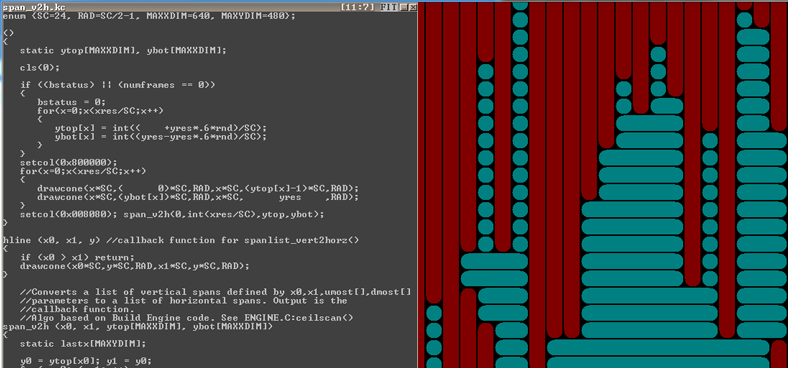
Комментарии Кена Силвермана:
ceilscan() и florscan() сложны, потому что они преобразуют список вертикальных диапапзонов в список горизонтальных диапазонов. Именно для этого нужны все эти циклы while. Я сделал это, потому что накладывать текстуры на потолки и полы без наклона гораздо быстрее в горизонтальном направлении. Это критически важная оптимизация движка, которую вы, наверно, не заметили. Я видел похожие циклы while и в исходном коде Doom.
Ken sent me an evaldraw script , span_v2h.kc , showing how ceilscan () and florscan () convert a list of vertical ranges to a list of horizontal ranges:
displayrest method:

displayrest taken from the game module . The main costs here are again for rendering (weapons). The status bar is not rendered every frame, it is inserted only when the ammunition counter changes.Interesting facts about VGA and VESA
Thanks to the X-Mode VGA, most players ran Build at 320x240. But thanks to the VESA standard, the engine also supports Super-VGA resolution. The vanilla sources are equipped with the VESA code, which provides a portable resolution definition and rendering.
Nostalgists can read about programming for VESA in this good guide . Today in the code leaving only the names of methods, for example
getvalidvesamodes().Sound engine
At one time, Duke3D had an impressive sound system engine. He could even mix sound effects to simulate reverb. You can read more about this in reverb.c .
Legacy code
Build code is very hard to read. I have listed all the reasons for these difficulties on the Duke Nukem 3D and Build engine: Source code issues and legacy page .
Recommended Reading
Nothing. Climb better - it's awesome!
But if you insist, then you can read id as Super-Ego: The Creation of Duke Nukem 3D
- If you want to read about another game based on portals, I recommend Sean Barrett's excellent post- mortem about Thief: The Dark Project.
- Lots of interviews with Ken Silverman:
- November 21, 2005 , classicdosgames.com ( mirror ).
- 2005 , strifestreams.com ( mirror ).
- February 27, 2006 , 3drealms.com ( mirror ).
- March 25, 2010 misterdai.yougeezer.co.uk ( mirror ).
- May 1, 2012 videogamepotpourri.blogspot.ca ( mirror ).
[Translation of the second part of the article is here .]