Optimization of multicast traffic transmission in the local network using IGMP snooping

Hello! Today I would like to touch on the topic of multicast traffic transmission on a local corporate network, namely the operation of IGMP snooping technology on switches. It so happened that over the past week several people have approached me with questions about this technology. And I decided to prepare a short article describing this technology. But in the process of preparation, it turned out that brevity will not get off here, as there is something to write about. If you are interested in the issue of IGMP snooping, welcome to cat.
Quite often, we don’t particularly think about how multicast traffic is transmitted within our corporate network L2 domain. Let me remind you that multicast traffic (aka “multicast traffic”) is designed to transfer data to a specific group of devices. By default, the switch transmits multicast traffic as broadcast (i.e., broadcast), i.e. to all ports without exception. This is due to the fact that in the multicast packet, a specially formed address that does not belong to anyone on the network is used as the MAC address of the recipient. If there is not much multicast traffic, this does not create big problems and most often the administrator does not take any measures to optimize its transmission. If there is a lot of such traffic or you just want to “comb” the network, the task is to limit its distribution. Here various technologies for optimizing the transmission of multicast traffic at the data link level (IGMP snooping, CGMP, etc.) come to the rescue. The most common and multi-vendor technology is IGMP snooping. IGMP snooping is enabled by default on many devices. For example, this is true for Cisco switches. But as often happens, happiness does not succeed in getting out of the box in all cases. Enabling IGMP snooping does not always give the intended result, and for some reason multicast traffic continues to flow from all ports for some reason. Let's try to figure it all out. happiness in the box is far from being obtained in all cases. Enabling IGMP snooping does not always give the intended result, and for some reason multicast traffic continues to flow from all ports for some reason. Let's try to figure it all out. happiness in the box is far from being obtained in all cases. Enabling IGMP snooping does not always give the intended result, and for some reason multicast traffic continues to flow from all ports for some reason. Let's try to figure it all out.
You should start with the abbreviation IGMP. We all know that when a device appears on the network that wants to receive certain multicast traffic, this device reports its desire through the IGMP (Internet Group Management Protocol) protocol. On many devices, IGMP version 2 is used by default. Messaging of this protocol in the simplest case is as follows:
- The device, when it decides to receive multicast traffic, sends its request in an IGMP Membership Report message (hereinafter IGMP Report). It indicates what exactly the device wishes to receive. The address of the requested multicast group is specified as the destination IP address. This message is primarily intended for the nearest router. After all, it is he who is responsible for the transfer of traffic between the local segment and the rest of the network.
- Upon receiving such a message, the router starts broadcasting the requested multicast traffic to this network segment. Of course, this happens provided that the router itself participates in the transmission of multicast traffic and receives the necessary traffic.
- To be sure that there are still multicast traffic recipients on the network, the router periodically sends an IGMP General Membership Query message (hereinafter IGMP General Query). After all, if nobody is already there, why in vain "clog" this segment of the network with traffic that nobody needs.
- In response to the IGMP General Query, the router receives an IGMP Report message . Usually it is sent by one of the recipients of multicast traffic. The rest, having heard this message, are simply silent, since one confirmation for each group is enough. The choice of who will respond to the router is implemented through the Report Suppression mechanism.Report suppressionIf we have many recipients of multicast traffic in our network, their responses to IGMP General Query can generate a sufficiently large number of IGMP Report messages. Since the router only needs to receive one such message, the following optimization mechanism is used. The IGMP General Query message indicates the Maximum Response Time (MRT) during which the router waits for a response. The client, having received the IGMP General Query, selects an arbitrary timer value from 0 to MRT. As soon as the selected timer expires, the client sends an IGMP Report message. This only happens if the client has not received an IGMP Report from some other recipient before.
- When a device no longer wants to receive multicast traffic for a specific group, it sends an IGMP Leave message .
- The router responds with an IGMP Membership Group-Specific Query (hereinafter IGMP Group-Specific Query) message , specifying whether there are devices on the network that want to receive traffic for this group. Typically, the router sends two of these messages. If there are such devices on the network, they will respond. If not, the router will stop broadcasting traffic to the local network segment.
You can read more about the operation of the IGMP protocol, and generally about multicast traffic, for example, in the series of articles in the network for the smallest .
Since all IGMP messages go through the switch, he could analyze them to determine which ports the multicast traffic recipients are on. And then, based on this information, transmit traffic only to where it is needed. Actually, this is exactly what IGMP snooping technology does.
The implementation of IGMP snooping by different manufacturers of network equipment may differ in some nuances. But in general, the scheme of work is similar. I propose in general terms to consider its work on the example of Cisco switches. Next, we look at the whole process in more detail:
- The first thing the switch does is determine where the router (s) are. To do this, he listens to the presence of IGMP General Query, PIM, DVMRP, etc. messages on the network.
- The device sends an IGMP Report when it wants to receive this or that multicast traffic. This message intercepts the switch. From it, the switch receives the following information: a device with such a MAC address located behind a specific port wants to receive traffic from such a multicast group. Moreover, for the switch when identifying a multicast group, the first thing that matters is not the IP address of this group (the IP addresses of multicast groups are in the range 224.0.0.0 - 239.255.255.255), but its MAC address. It is easier for a switch to work with addressing at the link level. As we know, a MAC address is formed according to a certain rule from the IP address of a multicast group. All this information is entered in the MAC address table of the switch.
Next, the switch sends an IGMP Report to the router.containing the same information as was received from the device. - When the router receives an IGMP Report message, it begins to transmit multicast traffic. But since the switch knows where the device is located that wants to receive it, it relays traffic only to a specific port. Now in the MAC address table there is an entry with the MAC address of the multicast group that looks at a specific port.
- Periodically, the router sends an IGMP General Query to the network . The switch sends it through all ports.
- Upon receiving the IGMP General Query , the device responds with an IGMP Report message . The switch intercepts it and sends it only towards the router. Other recipients of multicast traffic do not receive this message. And, therefore, they respond with their IGMP Report . Therefore, the operation of the Report Suppression mechanism is disrupted. This is necessary to identify all recipients of multicast traffic. Otherwise, the client, having heard the IGMP Report from another, decides that he does not need to respond, and the switch does not know about his presence. Having received from all IGMP Report, the switch updates its records. It makes no sense to send all IGMP Report messages to the router, so only one is sent - the very first.
- If a device decides to stop receiving traffic for a specific multicast group, it sends an IGMP Leave message . The switch, as usual, intercepts it.
- Firstly, the switch will check if there are other multicast traffic recipients behind the same port (where the IGMP Leave message came from). Indeed, another switch can be connected to this port. To do this, it sends an IGMP Group-Specific Query message. If there is no response, the switch simply removes the MAC address of the multicast group from this port. If a response is received, it continues to transmit traffic through this port.
- Next, the switch checks to see if there are other multicast traffic recipients for this group on it, but located behind other ports. To do this, he simply looks at his MAC address table.
- If there are such recipients, the switch does nothing else. It makes no sense to send an IGMP Leave message to the side of the router.
- If this was the last recipient for this multicast group, the switch sends an IGMP Leave message to the router.
- If there are such recipients, the switch does nothing else. It makes no sense to send an IGMP Leave message to the side of the router.
- After receiving an IGMP Leave message , the router sends IGMP Group-Specific Query messages , which the switch in turn sends through all its ports. Of course, no one responds and the router stops transmitting traffic for this group.
So, in general terms, we have analyzed the theoretical foundations. Let's try to see how it looks in practice. Our network topology will look like this:
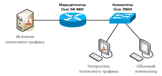
The source and receiver of streaming multicast traffic will be implemented through the VLC media player (hereinafter VLC player).
IGMP snooping is disabled, the source of multicast traffic is on a different network.
Let's start by considering the transmission of multicast traffic without using IGMP snooping technology. First, turn off IGMP snooping. As we recall, on Cisco equipment it is enabled by default:
cbs-sw-2960x#conf t
cbs-sw-2960x(config)#no ip igmp snooping
cbs-sw-2960x(config)#exit
cbs-sw-2960x#
cbs-sw-2960x#sh ip igmp snooping
Global IGMP Snooping configuration:
-------------------------------------------
IGMP snooping                : Disabled
On the router, turn on the routing of multicast traffic and run the protocol for routing multicast traffic PIM (Protocol Independent Multicast) in dense-mode. We do not have a regime. The main thing is that the router runs IGMP on the interface we need and ensures the transmission of multicast traffic through itself.
At the source, turn on the VLC player in streaming traffic mode. This will be our source of multicast traffic. We will use 230.255.0.1 as the group address. We will only transmit audio over the network. As the transferred composition, choose Adele Rolling in the Deep. The moment is important, since it is it that is best transmitted over the network (fact verified).
A bit of a thorny path at the very beginning
I ran into the problem of routing multicast traffic when setting up the first computer, which was supposed to be the source. As experimental, I took several laptops that are used by the company's engineers.
I installed the VLC player, set up the streaming audio and ... I did not see anything in the Wireshark dump on the external interface of this computer.
Looking at the routing table, I saw two routes to the network 224.0.0.0/4 with exactly the same metric 276. Moreover, the first route in the list went through a certain interface with the address 169.254.55.11. And only the second was the route through the normal interface of this computer (172.17.16.11).

In this regard, all multicast-packages were wrapped in an incomprehensible interface. Having looked at network connections, I found the activated Cisco Systems VPN Adapter interface. This interface appears on the system when the Cisco VPN client is installed on the computer. This is a fairly old solution for connecting via VPN and, apparently, they simply forgot to delete it.

Disabling this interface solved the problem.
I installed the VLC player, set up the streaming audio and ... I did not see anything in the Wireshark dump on the external interface of this computer.
Looking at the routing table, I saw two routes to the network 224.0.0.0/4 with exactly the same metric 276. Moreover, the first route in the list went through a certain interface with the address 169.254.55.11. And only the second was the route through the normal interface of this computer (172.17.16.11).
In this regard, all multicast-packages were wrapped in an incomprehensible interface. Having looked at network connections, I found the activated Cisco Systems VPN Adapter interface. This interface appears on the system when the Cisco VPN client is installed on the computer. This is a fairly old solution for connecting via VPN and, apparently, they simply forgot to delete it.
Disabling this interface solved the problem.
Next, on the client, turn on the VLC player in the mode of receiving streaming audio for the group 230.255.0.1.
And again the problems ...
When I moved on to setting up the streaming audio receiver, it didn't work right away. Then I was not at all surprised, but immediately climbed into the routing table. On this computer, the symptoms were identical: multicast packets did not appear on the wired interface.

And again, I found two routes to the network 224.0.0.0/4 with exactly the same metric 306. But now the first was the standard loopback interface route. Usually the route metric for this interface is larger, metrics through other interests. For some reason, in my case they were equal.
As it turned out, someone on this laptop manually set the wired interface metric.

After I checked the “Automatically learn metrics” checkbox, multicast packages began to leave normally from this computer.
As a result, both computers had a problem with routing multicast traffic, but in each case the source of the problem was its own.
And again, I found two routes to the network 224.0.0.0/4 with exactly the same metric 306. But now the first was the standard loopback interface route. Usually the route metric for this interface is larger, metrics through other interests. For some reason, in my case they were equal.
As it turned out, someone on this laptop manually set the wired interface metric.
After I checked the “Automatically learn metrics” checkbox, multicast packages began to leave normally from this computer.
As a result, both computers had a problem with routing multicast traffic, but in each case the source of the problem was its own.
We immediately see how multicast traffic went. In our case, these are streaming packets that use the UDP protocol at the transport level.

Do not forget about TTL
It is worth noting that by default the VLC player sets the TTL for streaming packets to 1. This means that such packets cannot be transferred to another network, i.e. routed. Therefore, for our case, in the VLC settings, the TTL value was set to more than one.
The dump shows that the recipient requested traffic (sent an IGMP Report message) and the router immediately started broadcasting the necessary multicast traffic to the network. There are two complete IGMP Report messages. Apparently, the second VLC player sends for fidelity. One message would be enough.
We check the routing table of multicast traffic on the router. Entries appeared in it, indicating where the traffic is coming from and where:
cbs-rtr-4000#sh ip mroute
IP Multicast Routing Table
Flags: D - Dense, S - Sparse, B - Bidir Group, s - SSM Group, C - Connected,
       L - Local, P - Pruned, R - RP-bit set, F - Register flag,
       T - SPT-bit set, J - Join SPT, M - MSDP created entry, E - Extranet,
       X - Proxy Join Timer Running, A - Candidate for MSDP Advertisement,
       U - URD, I - Received Source Specific Host Report,
       Z - Multicast Tunnel, z - MDT-data group sender,
       Y - Joined MDT-data group, y - Sending to MDT-data group,
       G - Received BGP C-Mroute, g - Sent BGP C-Mroute,
       N - Received BGP Shared-Tree Prune, n - BGP C-Mroute suppressed,
       Q - Received BGP S-A Route, q - Sent BGP S-A Route,
       V - RD & Vector, v - Vector, p - PIM Joins on route,
       x - VxLAN group
Outgoing interface flags: H - Hardware switched, A - Assert winner, p - PIM Join
 Timers: Uptime/Expires
 Interface state: Interface, Next-Hop or VCD, State/Mode
(*, 230.255.0.1), 00:29:20/stopped, RP 0.0.0.0, flags: DC
  Incoming interface: Null, RPF nbr 0.0.0.0
  Outgoing interface list:
    GigabitEthernet0/0/1.115, Forward/Dense, 00:29:20/stopped
(172.17.16.11, 230.255.0.1), 00:03:27/00:02:32, flags: T
  Incoming interface: GigabitEthernet0/0/1.116, RPF nbr 0.0.0.0
  Outgoing interface list:
    GigabitEthernet0/0/1.115, Forward/Dense, 00:03:27/stopped
We see that the source of multicast traffic is the host 172.17.16.11. At the same time, the recipients are behind the GigabitEthernet0 / 0 / 1.115 interface. The router only remembers where to send traffic. It does not maintain the base of the recipients themselves (such an opportunity is available in IGMPv3).
Let's look at a traffic dump on the client, filtered by IGMP messages:

- We press the “Play” button in the VLC player and our computer asks for multicast traffic for group 230.255.0.1 by sending an IGMP Report message. As we have already noted, he sends two such messages.
Upon receiving this message, the router begins broadcasting multicast traffic (streaming audio) to the local network and on our client we begin to hear music transmitted over the network. - Periodically (every 60 seconds), the router sends an IGMP General Query message.
- Our computer responds to this message by sending IGMP Report to group 230.255.0.1 in the opposite direction.
- We click the “Stop” button in the VLC player and our computer sends an IGMP Leave message that he no longer wants to receive multicast traffic for group 230.255.0.1.
- The router, in response to the IGMP Leave, sends an IGMP Group-Specific Query message for 230.255.0.1. He wants to understand if there are other recipients in this network segment. Exactly 1 second later, the router sends an IGMP Group-Specific Query retry message. And after another 1 second, not receiving a single IGMP Report, it stops transmitting multicast traffic to this network segment.
- Periodically, the router continues to send an IGMP General Query message. But since our computer is no longer interested in receiving anything, it does not answer anything.
Since IGMP snooping is turned off on the switch, all multicast traffic is sent (flooded) to all ports in our VLAN while there is at least one recipient. When there are no more recipients, the router will immediately stop transmitting traffic to this network segment.

Dump traffic from a computer in the same network segment, but not involved in receiving streaming traffic:

The same will be true for all IGMP messages. They will be sent to all ports without exception. Which is absolutely logical, since in all these messages a multicast address is used as the recipient address.
IGMP snooping is enabled, the source of multicast traffic is on a different network.
Now let's move on to the situation when IGMP snooping is enabled on the switch. Launch IGMP snooping on the Cisco 2960x:
cbs-sw-2960x(config)#ip igmp snooping
cbs-sw-2960x(config)#exit
cbs-sw-2960x#
cbs-sw-2960x#sh ip igmp snooping
Global IGMP Snooping configuration:
-------------------------------------------
IGMP snooping                : Enabled
First, check if the switch was able to find the router. As we recall, this is the first item on the IGMP snooping task list:
cbs-sw-2960x#sh ip igmp snooping mrouter
Vlan    ports
----    -----
 115    Gi1/0/19(dynamic)
We see that our router hid behind the port Gi1 / 0/19. As we previously discussed, the switch spies on the presence of packets on the network that indicate the presence of a router. In the case of the 2960x, the switch waits for IGMP General Query, PIM, or DVMRP packets.
Sep 17:39:39 MSK: IGMPSN: router: PIMV2 Hello packet received in 115
Sep 17:39:39 MSK: IGMPSN: router: Is not a router port on Vlan 115, port Gi1/0/19
Sep 17:39:39 MSK: IGMPSN: router: Is not a router port on Vlan 115, port Gi1/0/19
Sep 17:39:39 MSK: IGMPQR: vlan_id 115: querier/multicast router detected on port Gi1/0/19 in Disabled state
Sep 17:39:39 MSK: IGMPSN: router: Created router port on Vlan 115, port Gi1/0/19
Sep 17:39:39 MSK: IGMPSN: mgt: Reverting flood mode to only multicast router ports for Vlan 115.
Sep 17:39:39 MSK: IGMPSN: Adding router port Gi1/0/19 to all GCEs in Vlan 115
Sep 17:39:39 MSK: IGMPSN: added rport Gi1/0/19 on Vlan 115
Sep 17:39:39 MSK: IGMPSN: router: Learning port: Gi1/0/19 as rport on Vlan 115
The switch saw the PIMV2 Hello message from the router on port Gi1 / 0/19 and added information about it to itself.
We start our streaming audio broadcast again and see what we have on the router:
(*, 230.255.0.1), 00:00:12/stopped, RP 0.0.0.0, flags: DP
  Incoming interface: Null, RPF nbr 0.0.0.0
  Outgoing interface list: Null
(172.17.16.11, 230.255.0.1), 00:00:12/00:02:47, flags: PT
  Incoming interface: GigabitEthernet0/0/1.116, RPF nbr 0.0.0.0
  Outgoing interface list: Null
A traffic source appeared - 172.17.16.11. There are no recipients yet, as evidenced by the line: Outgoing interface list: Null.
We launch the VLC client, click the "Play" button and enjoy the music. In parallel, we look at Wireshark, where we see how multicast streaming packets go:

Now the fun part. We analyze the IGMP messages at the junction of the receiver-switch and switch-router.
Let's go through the main steps:
1. After clicking the "Play" button in the VLC player, our computer asks for multicast traffic for group 230.255.0.1 by sending an IGMP Report message.

Note Packets on the receiver
The switch, when it receives the IGMP Report message, enters information that there is a traffic receiver for the group with MAC address 01: 00: 5e behind its port (in our case, it is GE0 / 0/15): 7f: 00: 01.
Remark . It will not be possible to find a record of this MAC address on the switch. It does not appear anywhere, including in the standard output “show mac address-table”.
2. IGMP Report goes to the router. If we look into the message itself, we will see that this is an original message from our PC. The switch simply forwarded it to the port where the router is connected:

Note Packets on the router. The underlined MAC address belongs to the PC.
If there was already a client on the switch that received traffic for group 230.255.0.1, the switch would just start broadcasting traffic through our port (GE0 / 0/15) and would do nothing more. This is logical, since the switch would already have the necessary traffic, which should simply be wrapped on another port. But in our example, this client is the first.
3. The router starts broadcasting streaming traffic to the local network.

Note Packets on the router
4. The switch, in turn, sends traffic to port GE0 / 0/15, where our PC is connected.

Note Packets at the destination
5. The computer sends a second request for multicast traffic (specific implementation of IGMP support on the VLC player).

Note Packets on the receiver
Since it does not fit very well with the normal behavior, the switch discards this message. In this regard, we no longer see it on the router.
6. Periodically, the router sends IGMP General Query messages.
7. The switch translates them unchanged to all of its ports.

Note Packets on the recipient. The underlined MAC address belongs to router
8. The computer responds to this message by sending IGMP Report to group 230.255.0.1 in the opposite direction.
9. The switch forwards the first received IGMP Report message (and in this example, the message from our computer is the first one) to the side of the router.

Note Packets on the router. The underlined MAC address belongs to the recipient.
The switch receives the first IGMP Report message and forwards it only to the router. This message is not transmitted to other recipients, unlike the usual scheme of work without IGMP snooping. Those. Report Suppression mechanism is broken. Thus, each recipient will be forced to send their IGMP Report message in response to the IGMP General Query. Upon receiving such messages, the switch updates its base for matching recipients of multicast traffic and internal ports.
10. Press the “Stop” button in the VLC player. The computer sends an IGMP Leave message stating that it no longer wants to receive multicast traffic for group 230.255.0.1.

Note Packets at the destination
11. An IGMP Group-Specific Query message is sent to the computer for group 230.255.0.1. If we expand it, we will see that the switch sent this message:

Note Packets on the recipient. The underlined MAC address belongs to the switch. In this case, the switch used the IP address of the sender 172.17.15.1 (this is the address of the router)
i.e. Upon receiving an IGMP Leave message, the switch checks to see if there are any other devices on this port who want to receive multicast traffic for group 230.255.0.1.
The switch does not send anything to the router. So far, the switch does not disturb the router in any way, since it is not yet sure that something needs to be done with multicast traffic.
12. Exactly one second later, the switch sends a repeated IGMP Group-Specific Query message.
13. And after another second, not receiving a single IGMP Report, it stops sending multicast traffic to this port.

Note Packets on the recipient. The broadcast stopped at 13: 32: 58: 58
14. After the switch realized that there were no more recipients at the port where the IGMP Leave message was received, it checks to see if it has receivers at the other ports. To do this, he looks at the MAC address table for the presence of entries for the MAC address 01: 00: 5e: 7f: 00: 01 (as we recall, this is the MAC address of the group 230.255.0.1). If other receivers were connected to this switch, the switch would stop there and continue to transmit multicast traffic. But in our case, there are no other recipients. Therefore, it sends an IGMP Leave message to the router.

Note Packets on the router. The underlined MAC address belongs to switch
15. After receiving the IGMP Leave message, the router starts checking for other traffic recipients. He does not know that the switch has already checked everything himself. The router sends an IGMP Group-Specific Query message for group 230.255.0.1.
16. The switch translates this message to all of its ports. Including the port where our computer is connected. As you can see from the dump, this message is now sent by the router:

Note Packets on the recipient. The underlined MAC address belongs to router
17. One second after sending the first message, the router sends a repeated IGMP Group-Specific Query message.
18. And after another second, without receiving a single IGMP Report (which is expected, since we already know that no one has responded to the switch before), the router stops sending streaming traffic to this segment of the local network.

Note Packets on the router. Broadcasting stopped at 13: 33: 00: 65
19. The router continues to send an IGMP General Query message once a minute.
20. The switch, in turn, translates it to all its ports.
Final dump from devices
I specifically filtered the dumps in such a way that it was exactly visible at what point the traffic broadcast began and at what point it ended. I removed most of the UDP packets for clarity.
Dump on the receiver (receiver-switch):

Dump on the router (switch-router):

Dump on the receiver (receiver-switch):
Dump on the router (switch-router):
In summary, we can say the following. The switch intercepts all IGMP messages from clients. Analyzes them. And, depending on the situation, forwards these messages to the router or deletes. Also, the switch itself is involved in the process of creating IGMP messages. When the last client decides to stop receiving multicast traffic, we have two checks for recipients. The first is the switch, and the second is the router. Throughout this scheme, the router behaves in exactly the same way as when we do not have IGMP snooping on the switch. Those. the router does not realize that there is a switch with IGMP snooping enabled.
Let's look at a dump of computer traffic, which is not involved in receiving streaming traffic, but is located in the same local network.

Note The underlined MAC address belongs to the router.
From the dump it can be seen that this computer for all the time received only two types of messages and not a single multicast-packet for streaming:
- The IGMP Group-Specific Query message that the router sent when there were no more recipients of multicast traffic on the network.
- The IGMP General Query message that the router periodically sends.
Thus, when IGMP snooping is enabled, the switch, firstly, sends multicast traffic for certain groups only to those ports where there are real recipients. Those. optimizes the transmission of this type of traffic.

Secondly, it reduces the number of IGMP messages towards the router. In fact, the router only learns about the presence of the first and the disconnection of the last recipients of multicast traffic. Connecting and disconnecting other recipients is fully regulated by the switch, which is logical.
Third, it significantly reduces the number of IGMP messages that go to all ports on the switch that are not involved in the transmission of multicast traffic. As we recall, in the absence of IGMP snooping, all IGMP packets are forwarded to all ports without exception.
It remains to see what we see on the switch itself:
cbs-sw-2960x#sh ip igmp snooping groups
Vlan      Group                    Type        Version     Port List
-----------------------------------------------------------------------
115       230.255.0.1              igmp        v2          Gi1/0/14, Gi1/0/15,
                                                           Gi1/0/19
We see that the recipients of multicast traffic for group 230.255.0.1 are located behind ports Gi1 / 0/14, Gi1 / 0/15 and Gi1 / 0/19. Behind the Gi1 / 0/19 port is the router itself. The switch automatically added a port with a router. For more detailed information on the switch, you can run the debug ip igmp snooping debugger.
IGMP snooping is enabled, the source of multicast traffic is on the same network
And so, when the source is somewhere else in our network, everything works great. But let's now transfer our source of multicast traffic to the same segment of the network where the recipients are located. The situation is quite mundane. For example, we have a system for receiving television channels from a satellite and several STB consoles. Or we use a VLC player or, for example, video surveillance cameras that transmit data to several consumers located in the same network segment. Another case is the transmission of multicast traffic between a wireless network controller and access points. How will IGMP snooping work in this situation?
For the purity of the experiment on the router, disable PIM, since now we no longer need to route multicast traffic.
It makes no sense to consider the option with IGMP snooping disabled: all traffic will simply be transmitted as broadcast. Therefore, we check that IGMP snooping is turned on, and start streaming on our impromptu server. We do not start the VLC player on the client (i.e., the client does not send any IGMP messages).
We see that multicast traffic immediately began to pour on our computer, acting as a client:

Strange, because IGMP snooping is enabled. Let’s see how the situation will change if you start the VLC player on the client and connect to the group 230.255.0.1 (we continue to use it to broadcast our streaming audio). We press the Play button, we see how our computer sent the IGMP Report message, we begin to hear music. It is clear that multicast traffic came to the computer all the time. Just now the VLC client began to process it:

IGMPv3 Messages
Я думаю, Вы уже заметили, что в дампе фигурируют пакеты IGMPv3. При этом ранее мы везде видели только IGMPv2. Обусловлено это тем, что на оборудовании Cisco по умолчанию используется IGMPv2. А в ОС Windows (7, 8, 10) используется IGMPv3. Во всех предыдущих случаях на маршрутизаторе был включён IGMP и клиенты, получая периодически от маршрутизатора сообщения IGMPv2 General Query, автоматически переключились также на вторую версию протокола. В текущем сценарии на маршрутизаторе отключён IGMP, поэтому клиент использует третью версию протокола.
Now you need to make sure that the switch continues to send multicast traffic through all other ports. Or finally IGMP snooping started and the switch began to send traffic only to where there are clients. But no. Nothing has changed. On another computer that does not participate in our experiment, we see multicast traffic (I won’t give the dump itself, we already know multicast packets by sight). It is worth noting that in the dump we will not find any IGMP Report messages that our client sent earlier, and which, in theory, should also be sent to all ports. So IGMP snooping on the switch still partially works: at least the switch intercepts IGMP messages.

Just right to look into the console of the switch. Recipient information for various groups is empty:
cbs-sw-2960x#sh ip igmp snooping groups
cbs-sw-2960x#
Running the debugger (debug), we see:
Sep 13:54:01 MSK: IGMPSN: Received IGMPv3 Report for group v3 received on Vlan 115, port Gi1/0/15
Sep 13:54:01 MSK: IGMPSN: Rx IGMPv3 Report on Gi1/0/15 when Querier is not IGMPv3, Vlan 115.
Of these messages, the only thing that becomes clear is that the switch received an IGMPv3 Report message, while the version of one Querier does not recommend IGMPv3 (we'll talk about Querier a bit later). And what will we get if we switch IGMPv3 on our computer to IGMPv2 (this procedure is done through the registry). Suddenly start up.
We check. The behavior of the switch remains the same, but the messages in the debugger have changed:
Sep 15:07:08 MSK: IGMPSN: Received IGMPv2 Report for group 230.255.0.1 received on Vlan 115, port Gi1/0/15
Sep 15:07:08 MSK: IGMPSN: group: Received IGMPv2 report for group 230.255.0.1 received on Vlan 115, port Gi1/0/15
Sep 15:07:08 MSK: IGMPSN: router: Is not a router port on Vlan 115, port Gi1/0/15
Sep 15:07:08 MSK: IGMPSN: group: Skip client info adding - ip 172.17.15.11, port_id Gi1/0/17, on vlan 115
Sep 15:07:08 MSK: IGMPSN: No mroute detected: Drop IGMPv2 report for group 230.255.0.1 received on Vlan 115, port Gi1/0/15
From these messages, it becomes clear that the switch ignores the information in the IGMP messages (and even deletes them), since it does not have “mroute”. And here we begin to recall that the first point of the IGMP snooping program is to determine where the router is located. And it doesn’t matter if we are going to route multicast traffic or not. In the previous section, we checked the output of the command “show ip igmp snooping mrouter”. There was indicated the port number where our router was connected, sending IGMP General Query messages. So, a switch with IGMP snooping needs to know where the multicast router is located. The port on the switch where such a router will be connected is called the mrouter port (multicast router port). Without the mrouter port, IGMP snooping will not work normally. But we don’t have such a port, since we disabled IGMP on the router.
We turn IGMP back on on the router (for this we activate the PIM protocol on the interface). We verify that the mrouter port appears on the switch:
cbs-sw-2960x#sh ip igmp snooping mrouter
Vlan    ports
----    -----
 115    Gi1/0/19(dynamic)
And again we start our source of streaming audio. While the VLC player does not turn on. Check if traffic is sent to all ports on the switch. Not. The only thing where the switch now broadcasts multicast traffic is through the mrouter port. He always does this, since under normal conditions the router never sends IGMP Report messages to groups whose multicast traffic it will route. This means that the switch will not be able to find out whether this or that multicast traffic is necessary or not for the router.
Comment. When we considered schemes where the source of multicast traffic was on a different network, multicast packets were sent to the router from the source for exactly the same reason that we described. The router did not send IGMP Report messages for group 230.255.0.1 to the network with the source of multicast traffic.
As soon as we start the VLC player, the switch immediately starts transmitting multicast traffic to this computer. In general, the interaction between the client-switch-router within the IGMP protocol is no different from what we considered earlier when the source was on a different network. But there is a slight nuance.
Let's take a look at the dump received from the router (some of the UDP packets were filtered for greater clarity):

From the dump you can see the following:
- As expected, multicast traffic is constantly coming to the router.
- The router continues to work out the IGMP logic for group 230.255.0.1. To an IGMP Leave message, it sends IGMP Specific-Group Query messages.
- Но в отличии от предыдущего случая, когда маршрутизатор выясняет, что больше нет получателей для группы 230.255.0.1, маршрутизатор не может прекратить передавать multicast-трафик. Его инициатором в данном сегменте сети является совсем другое устройство (это хост с адресом 172.17.15.12).

And so, we realized that for IGMP snooping to work correctly on the Cisco switch, we need a router. But is it possible to get a mrouter port on a switch without starting IGMP on the router? Anyway, is it possible to do without a router? Yes, there are several ways for this. The first option is to statically register the mrouter port. He can watch anywhere. The main thing is to be. Of course, this is not the most elegant way. The second option is to start IGMP Querier mode on the switch. In this mode, the switch imagines itself to be a multicast router and starts sending and processing IGMP messages. At the same time, it will indicate itself as a mrouter-port:
cbs-sw-2960x#sh ip igmp snooping mrouter
Vlan    ports
----    -----
115    Switch
Our switch will also send IGMP General Query messages on its behalf. This is a big plus. Upon receiving it, the other switches on the network will decide that our switch is a multicast router, which means they will have their own mrouter ports. Thus, IGMP snooping will work correctly throughout the network.
Comment. The switch always transmits all multicast traffic through the mrouter port. If there is a lot of such traffic, it can easily clog trunk ports between switches, which will turn out to be ultimately mrouter ports. Therefore, it is worth approaching the network design carefully, choosing the correct location for devices that will play the role of IGMP Querier.
To summarize . In order for IGMP snooping to work correctly on Cisco switches, you must have at least one mrouter port on it. If there are no mrouter ports on the switch:
- A switch with IGMP snooping enabled (and, as we recall, it is enabled by default) transmits multicast traffic generated in this network segment as broadcast. It doesn’t matter if we have at least one recipient.
- The switch intercepts and deletes all IGMP Report messages.
If we have a mrouter port and IGMP snooping is enabled, the switch always sends multicast traffic from a local source through this mroute port. It does not matter if there is at least one to receive.
IGMP snooping and 224.0.0.X
When I first met IGMP snooping, the first thing I thought about was whether it is possible to restrict multicast traffic addressed to groups from the range 224.0.0.0-255 (224.0.0.0/24) using this technology. .
As we recall, this range of addresses is used only for local communications within one network segment (broadcast domain). Many IP addresses from it are reserved for various service protocols. For example, address 224.0.0.5 is used by OSPF, and address 224.0.0.10 is used by EIGRP. But since these addresses are used purely for local interaction, no mechanisms for connecting / disconnecting to these groups are used. Those. there will be no IGMP Report messages for these addresses. Therefore, they are all completely excluded from the IGMP snooping process and the Cisco switch will forward traffic for these groups to all ports.
There are exceptions
Бывают исключения в плане отсылки сообщений IGMP Report. Например, мой компьютер пытается присоединиться к группам 224.0.0.251 и 224.0.0.252. Это сервисы Multicast DNS и Link-Local Multicast Name Resolution, которые в своей работе используют механизм присоединения к группе.
Правда коммутатор Cisco считает такое поведение не достойным для сервисов, которые используют адреса, начинающееся с «224.0.0.». В связи с чем игнорирует сообщение IGMP Report.
Sep 17:27:36 MSK: IGMPSN: Received IGMPv2 Report for group 224.0.0.251 received on Vlan 115, port Gi1/0/15
Sep 17:27:36 MSK: IGMPSN: 224.0.0.251 is a Reserved MCAST address
Sep 17:27:36 MSK: IGMPSN: group: Received IGMPv2 report for group 224.0.0.251 received on Vlan 115, port Gi1/0/15 with invalid group address
Sep 17:27:37 MSK: IGMPSN: Received IGMPv2 Report for group 224.0.0.252 received on Vlan 115, port Gi1/0/15
Sep 17:27:37 MSK: IGMPSN: 224.0.0.252 is a Reserved MCAST address
Sep 17:27:37 MSK: IGMPSN: group: Received IGMPv2 report for group 224.0.0.252 received on Vlan 115, port Gi1/0/15 with invalid group address
Правда коммутатор Cisco считает такое поведение не достойным для сервисов, которые используют адреса, начинающееся с «224.0.0.». В связи с чем игнорирует сообщение IGMP Report.
В заключение
We examined the general aspects of IGMP snooping using Cisco equipment as an example. Moreover, the considered behavior is the default behavior. Behind the scenes were questions related to tuning various parameters of this technology (for example, time-outs between sending IGMP Group-Specific Query messages), changing the switch operation scheme if IGMP Leave messages are received from clients (for example, we know that there is definitely no port other devices), interaction with the STP protocol (more precisely, what to do when the network topology is being rebuilt), etc. Usually, these elements are already more vendor-dependent and are well described in the documentation.
If we look at switches from other manufacturers, we will also find IGMP snooping technology on many of them. Of course, there will be differences in the setup syntax, in some terms (for example, instead of the mrouter port, many use just a router port), various additions and parameters that can be tweaked. But for the most part, the general scheme of IGMP snooping will be similar to what we reviewed.