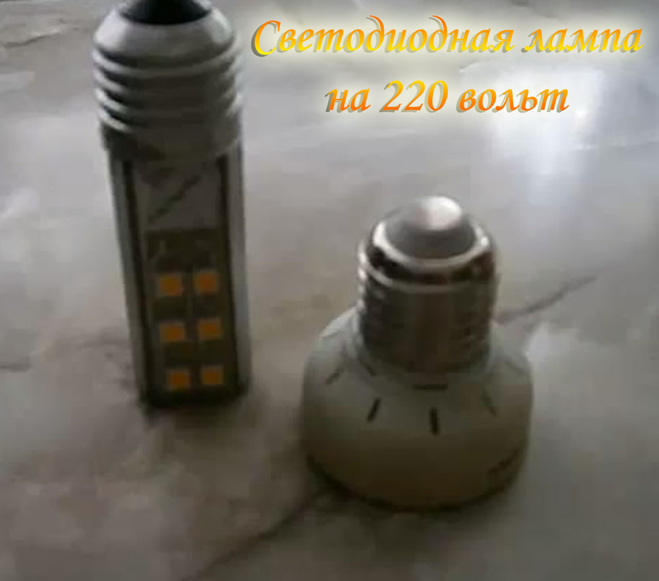
220 volt LED lamp
- Tutorial
Hello.
We didn’t live hard and nothing boded ill, but with a sharp rise in price of electricity, I thought about saving electricity and decided to start small, make LED lamps with minimal investment.
The circuit of the LED lamp is quite simple and does not require a higher education to assemble it, any beginner amateur radio amateur can assemble it.
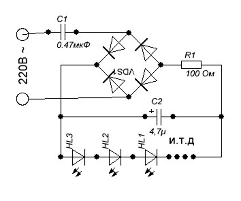
Pretty simple scheme, now a little about the scheme.
The capacitor C1 is selected directly by the current of the LEDs, I have smd5050 LEDs of 18 pieces, three crystals in one LED housing, totaling 54 LEDs connected in series.
One LED consumes 20 mA because the LEDs are connected in series, the current does not change, the capacitor set to 0.47 uF 400 volts and the current consumption is 17 mA, more and no need, let it be better if the supply is small.
Next is the diode bridge that protects the LEDs from reverse voltage, I put the diode bridge DB107S 1A 1000 volts, this bridge is quite enough for this circuit.
Next, we have a 100 ohm resistor, and it does not matter how many LEDs cost 1 or 10, the resistance does not change, but there is one thing, only the resistor power changes depending on the LED power.
For my 20 miles ampere LEDs, I installed a resistor with a capacity of 0.125 watts, but when I collected a half-watt LEDs and a consumption current of 180 mA, I put a resistor at 0.5 watts.
Next we have a C2 capacitor, it protects our LEDs from surges in the network, I took the capacitor from an economy bulb 4.7 microfarad 400 volts.
That's the whole circuit, now we turn to the printed circuit board.
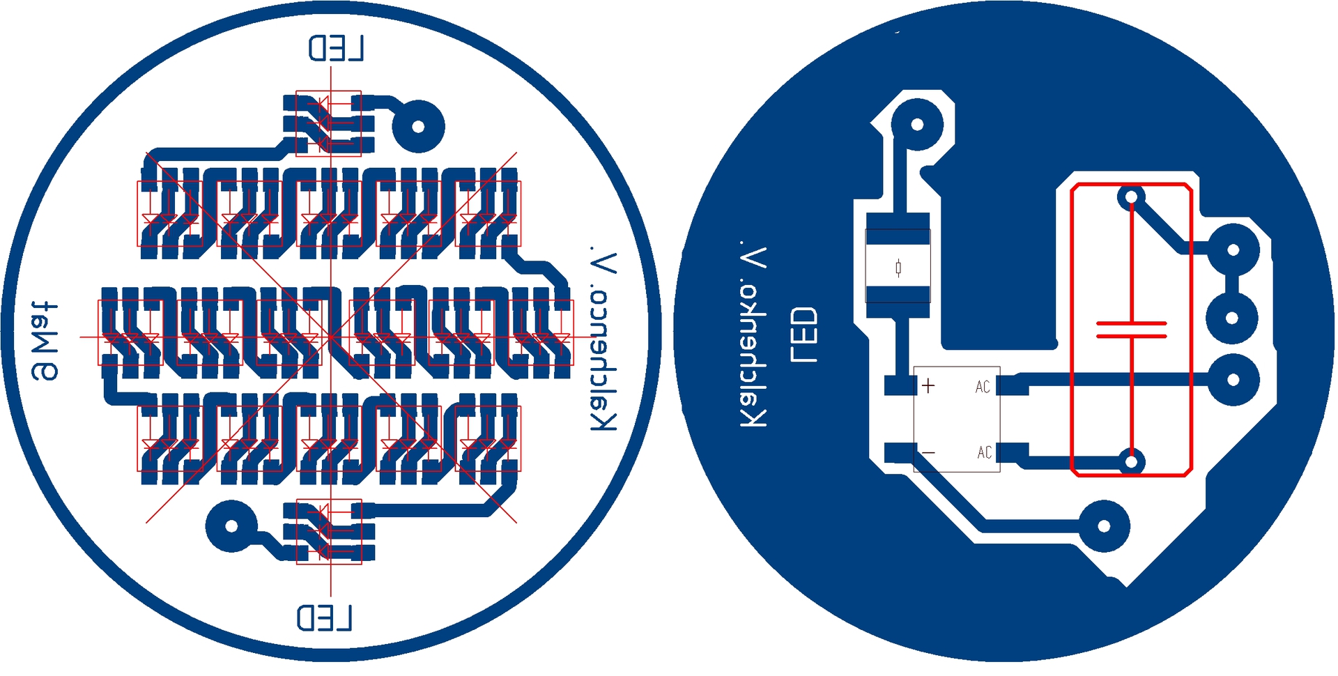
The printed circuit board is made on two-sided foil-coated fiberglass, the capacitor C2 is not indicated because I solder it parallel to the LEDs, and its legs also serve as jumpers on the second side of the printed circuit board.
In this way, I saved space on the board.
So actually we got such an LED lamp for the home in a couple of hours, and you can see the full overview of the LED lamp in this video clip. Thank you all, see you soon.