The nuances of working tools Target Length and Tuning Meter in PADS Professional / Xpedition
When tracing complex printed circuit boards using high-speed interfaces, engineers need to clearly control the length of critical signals, because at high frequencies each unaccounted millimeter of the conductor will greatly affect the integrity of the signal, and therefore the operation of your device as a whole.
In this article I will try to explain the logic of the Tuning Meter and Target Lengths tools, since they do not always calculate the lengths of the conductors in the same way.
As always, all the fun under the cut.
Overview
- How is the allowable length range of the conductor and its upper / lower limits calculated?
- Tuning meter vs. Target Lengths
- Why are there differences between lengths in the Target Length and what is displayed in the Tuning Meter?
In this article, the term FromTos (FT) is used to describe the physical connection between two pins (contacts), this concept is also used in the Constraints Manager (CM).
Example 1: Point-to-Point Connection
This is the simplest example - a two-point connection for a circuit consisting of 2 contacts. The minimum and maximum length of the conductor is set in the Constraint Manager, as shown in the figure below.
* Important note # 1: When the length is determined using the minimum / maximum length, the default tolerance setting in CM (Setup Settings - Design Configuration: Default Tolerances) is NOT applied!

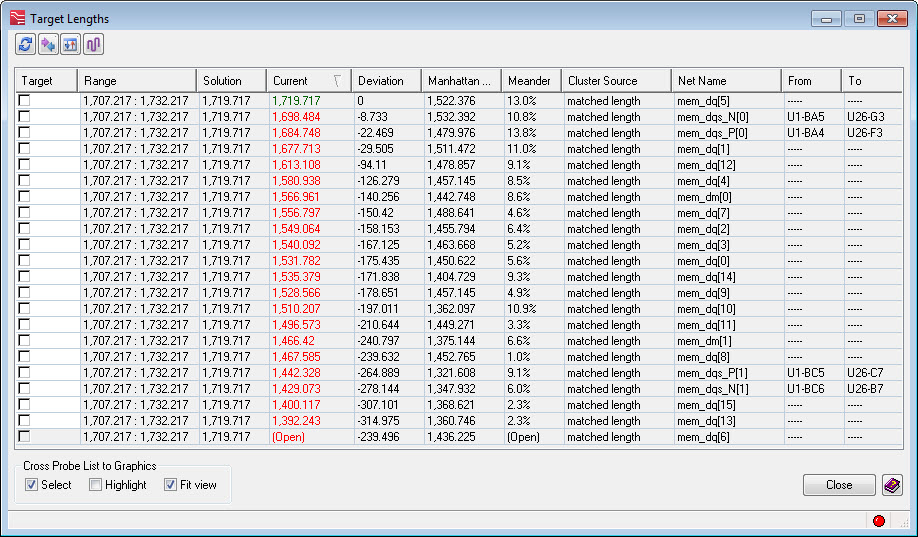
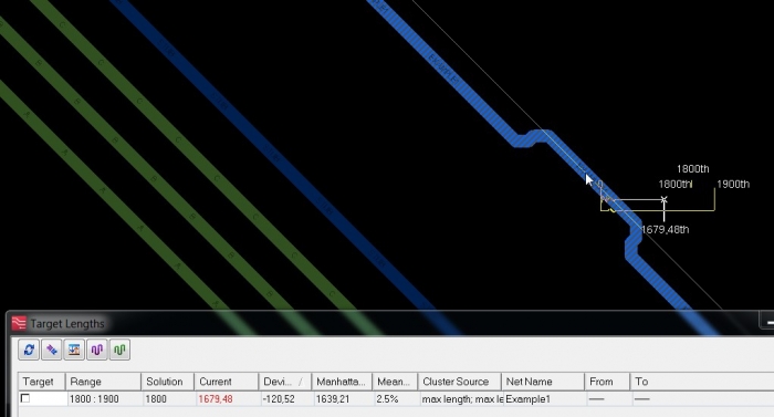
Both the Target Lengths dialog box and the Tuning Meter will display the current (Current) length and range (Range), in this case from 1800th to 1900th. Since the actual length of the divorced conductor is less than 1800th, the 1800th is displayed in the “Solution” column.
Example 2: MST type topology without vias
The second example is a 3-pin circuit, the topology of the MST (Minimum Spanning Tree) type, without interlayer transitions:

In this case, the Range is displayed as 1800: 1900, as we specified in CM. This conductor is traced with a length of 1805.95th, which is the smallest possible length for a given case. Thus, in the Solution column, the shortest attainable length is displayed at the 1805.95th.
In short, the solution depends on the current length of the conductor and the specified range:
- If the “Current” value is less than the lower limit of the limit => Solution = the lower limit of the range
- If the “Current” value is greater than the upper limit of the limit => Solution = the upper limit of the range
- If the “Current” value is within our range => Solution = current conductor length
To update the Solution value in the Target Length window, click the Refresh Solution icon.
Example 3: 3-pin circuit with user topology
This circuit is similar to the circuit used in Example 2, but now we have defined a user topology for it.
A custom topology is essentially a chained topology containing two FTs, one from pin 16 of IC5 to pin 9 of IC3 and the other from pin 9 of IC3 to pin 12 of IC3.
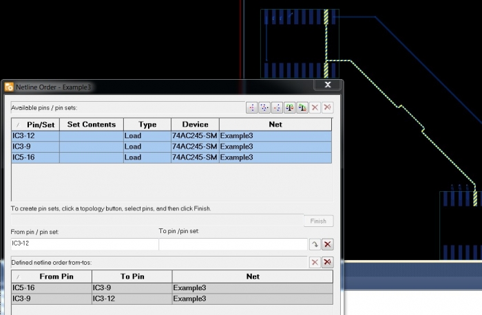
The same minimum / maximum limits are used (1800: 1900).
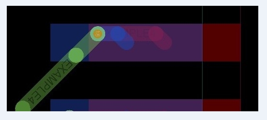
As we can see in the picture below, the track passes inside the IC3-9 contact pad, and then is output from the pad. This route piece, which is embedded in the pad, will also affect the overall length of the conductor. In addition, since there are now two FTs, the path segment that is highlighted below is part of both FTs — this is the total, the so-called stub length — the maximum distance from the path to the output for a T-shaped connection.
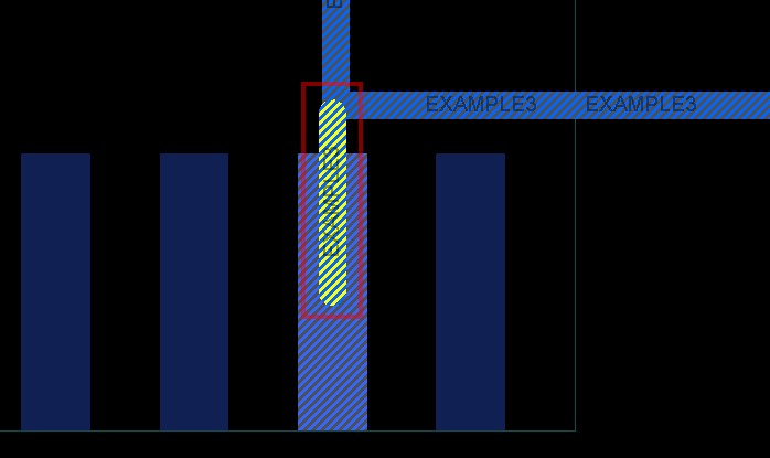
* Important note # 2: Trace segments that are embedded in the pads affect the overall length of the track and are taken into account when tracing.
Below you can see the cross-section tracing of our user topology:

The calculation of the target range depends on whether the FT length is inside or outside this range. Since the min / max value of the conductor length in CM is set as 1800: 1900 th, the whole range is 100 th, or 1850 ± 50 th. Two segments of the route are shown in green in the “Current” column, because their total length is within the tolerance:
363.02 + 1509.63 = 1872.65 th.
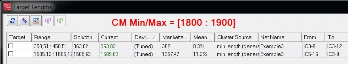
Two FTs are listed in separate lines, since each segment of the route can be adjusted individually.
Note that the “Current” values correspond to the sum of the lengths of the path segment and the hemp length:
For FT1 = 294,880 th + 68,144 th = 363.04 th
For FT2 = 1,441,486 th + 68,144 th = 1509,63 th
So, what is the achievable trim range for each track segment? Since only one chain can be tuned at a time, when setting up an FT2 segment, only the length of the route that does NOT have common segments with FT1 can be changed .
Note that the range of each individual section is the same as the range defined by the minimum / maximum values in the Constraint Manager, i.e. 100th or ± 50th.
When the algorithm determines the adjustment range for individual FT segments, it sets the upper boundary of the segment, taking the maximum value of the range defined in the CM, in this case 1900 th, and subtracts the length of the traces of the other segments included in this circuit. Remember that the total length of the stub lenght is not taken into account, therefore we get the following:
- для FT1 верхняя граница рассчитывается как 1900 th — 1441,486 th = 458,514 th. Целевой диапазон для FT1 получается [358,51: 458,51].
- для FT2, соответственно, 1900 th — 294.880 th = 1605.120 th. Целевой диапазон для FT2 получается [1505.120: 1605.120]
Пример 4: 3-контактная упорядоченная цепь с переходными отверстиями и общим сегментом трассы
In this example, the effect of the length of the transition hole itself is not taken into account (i.e., the Via Length Factor in the Setup> Setup Parameters> Via Definitions menu is zero).
The same minimum / maximum length [1800: 1900] is used as in the examples above. FTs (path segments) are defined in the same way in CM, where FT1 goes from IC2-3 (bottom layer) to IC3-18 (top layer), and FT2 goes from IC55-18 to IC2-3.

Please note that there is a common route that has a length of 46.278 th with a via (from 1 to 8 layers), but we do not take into account the length of the transition. Both the common track (shown in red) and the short track (shown in blue) are built into the corresponding pads. The length from the vias in the top layer to the center of the pad IC3: 18 is 21.278 th.
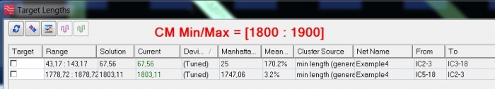
The definition of target ranges is performed by analogy with the previous example. The width of the range is set based on the Min / Max limit — 100 th or ± 50 th.
For FT1, the central value of the range is calculated as: 1850 th - 21.278 th = 1828.72 th. Thus, the target range for FT1 is 1828.72 th ± 50 th, or [1778.72: 1878.72].
For FT2, the central value of the range is: 1850 th - 93.26 th - 1663.57 th = 93.17 th, therefore, the target range is 93.17 th ± 50 th, or [43.17: 143.17].
Now let's consider the case when the FT length is out of range. In this case, the calculation is based on the current length and deviation, which is negative if the route is too short, and positive if the route is too long. The deviation is calculated by subtracting the value of “Solution” from the value of “Current”, as shown in the figure below.
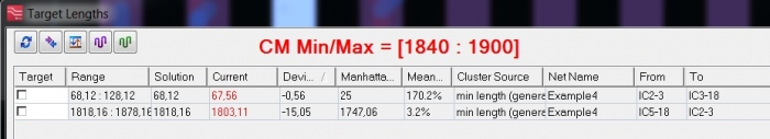
Change the CM range to [1840: 1900] or 1870 ± 30th.
In this particular case, notice the negative deviation. This means that both FTs are too short, and the algorithm for calculating the target range will take this into account.
For FT1, the lower target value (TL) is determined by adding (negative) deviations to the current length, since this will be the closest match, therefore
TL1 = 1803.11 + 15.05 = 1818.16 th.
Since we have a tolerance of ± 30 th, therefore, the target range is obtained [1818.16: 1878.16].
Similarly for FT2: TL2 = 67.56 + 0.56 = 68.12 th, the range is obtained [68,12: 128,12].
Example 5: 3-pin ordered chain with vias and a common path segment (including the vias length ratio)
In the last example, the length coefficient Via is introduced. This parameter can be configured via the Setup> Setup Parameters menu on the Via Definitions tab.
In this example, we have the following stack of layers:

Note: The thickness of the materials can be found in the Stackup Editor.
The track connects to the software on layer 1 and goes to layer 3. Another connection goes from layer 3 to layer 8.
Note that to calculate the length of the software, the copper thickness of the initial and final layers is NOT taken into account.
In cross-section, the signal topology will be as follows:
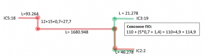
With the Len Lenthth Factor = 0 software length coefficient and a minimum / maximum length limit [1800: 1900], the target range in the Target Length window will look like the one below.
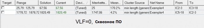
The value “Current” in this case is simply the length of the conductor, therefore:
FT2 = 93.264 + 1680.948 + 46.278 = 1820.49
FT1 = 21.278 + 46.278 = 67.556
When we set the length factor for the software Via Lenghth Factor = 1, we have The Target Length window will have the following result:
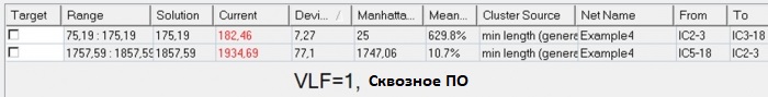
Since Via Lenghth Factor = 1, the system will add the length of the transition between layers to the length of the corresponding segments of the route, and the current length of these FromTos segments will increase:
Current2 = Route + PO1 + PO2 = 1820.49 + 27 7 = 86.5 1934,69 +
Current1 = track + Front ON = 67.556 + 114.9 = 182.46
And, since the length of segments is now too large, the upper limit of the range (TU) asschityvaetsya as:
TU1 = Current1 - Deviation1 = 1934.69 th - 77.1 th = 1857.59 th, therefore, the whole range is [1757.59: 1857.59]
TU2 = Current2 - Deviation2 = 182.46 - 7.27 = 175 , 19 th, the range is [75,19: 175,19].
Conclusion
The considered examples show how the algorithm for calculating the target length of the conductor, taking into account its topology, as well as the influence of the length of vias in the Target Length and Tuning Meter tools.